The first part of this chapter is designed to get complete beginners up to speed with an overview of the 3D Studio Max user interface, tools, and some functions. The version we’ll be covering is Max 2011; if you happen to have an earlier version, a lot of this information will still be accurate.
A trial version of the latest release can be downloaded from the Autodesk Web site. Just go to www.autodesk.com and look in the Products tab.
First of all, let’s have a brief look at the layout of the User Interface (or UI). Figure 1.1 is a screen grab of how 3ds Max appears when it’s launched. Let’s have a look at each of the main areas of the interface.
1. In the top left corner, we have a button which is the 3ds Max logo. Click on this to bring up the Application menu, which provides the file-management commands such as opening or loading a scene and the saving options.
2. To the right of this is the quick access toolbar, and it contains icons for saving, creating new scene, opening file, and the undo and redo commands.
3. Just below these we have the menu bar. This gives you access to all the tools and their settings in 3ds Max along with the create options for creating 3D shapes. It also contains all the preferences and software settings under Customize > Preferences.
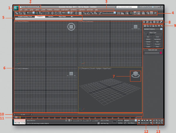
FIG 1.1 Layout of the user interface.
4. Below the menu bar is the main toolbar, which contains a lot of the basic tools we will need. Highlighted in the grab of the toolbar below are the select, move, rotate, and scale buttons. These are the tools we need to manipulate objects and meshes within 3ds Max.
Other options on this bar include the snap settings for snapping components using different methods. The selection options are also available here. Including the selection filter, a useful dropbox, will allow you to restrict selections to certain object types. This is very useful when dealing with complex scenes with many types of objects.
On the right side of the toolbar as seen in the image are the buttons to bring up the material editor and the rendering options.
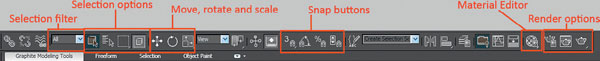
FIG 1.2
5. Beneath the main toolbar are the Graphite Modeling Tools. This section gathers all the standard edit tools related to polymodeling in one place. It really helps to speed up the modeling process.
6. The four windows highlighted by number 6 are the four default viewports. From the top left, these are the TOP view, FRONT view, LEFT view, and the PERSPECTIVE view. It is possible to arrange the viewports whichever way you want. To maximize or minimize the active viewport, the shortcut is ALT + W. The currently active viewport will always be highlighted by a yellow border.
You can also left-click and drag in the intersection between viewports to resize them. Right-click in the intersection again and select reset layout to restore the default four panel view.
7. Highlighted here is the viewcube. This is a very handy tool for quickly changing the orientation of a camera or changing the viewport with one click. You can do this by clicking on either a direction on the compass around the viewcube or clicking on the cube itself.
When the cube is displayed in a 3D viewport, you can select any corner, side, or face to position the camera. To change to a standard view, click on the center of a face.
When in a standard view, four arrows will appear around the viewcube allowing you to cycle through all the standard viewports; for example, front, back, and top. To go back to a 3D view, click on a side or a corner.
You can also hold the LMB (left mouse button) and drag to rotate the viewcube and viewport.
Below is an image of the viewcube. The viewcube on the left is from the perspective viewport, and the right one is from the front viewport.
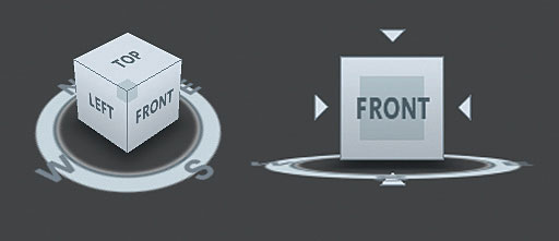
FIG 1.3
8. This is the command panel, and it consists of six panels that give you access to most of the modeling features of 3ds Max. To display a different panel, you click its tab at the top of the command panel.
The most important panels for beginners are the create panel and the modify panel.
Create panel: The create panel gives you access to the primitive shapes which are good starting points for creating models. Also featured within this tab are shapes, lights, and cameras. There are seven categories. All of these can be created by selecting what you want in the menu with the LMB and then clicking the LMB in the viewport. Then the item will appear.
Modify panel: The modify panel is where you can change the creation parameters of an object and also where you can apply modifiers to objects to reshape them. The modify panel’s contents will contain different parameters, depending on what category or type of object is selected. We will be dealing with all these various parameters as we encounter them throughout the book.
9. These are the object categories within the create panel. This is the panel which contains the basic primitive objects. The drop-down box below the icons allow you to access more advanced shapes and items. By default it is on standard primitives.
10. This is the time slider. This displays the current frame the time slider is on and how many frames are in the total range. To move the slider, you can either select it and hold the LMB and drag it along back and forth or you could use the playback controls to the right (12).
11. The track bar sits below the time slider and is a timeline displaying frames in increments. It is mainly used for adjusting keys. Moving, copying, or deleting them.
12. These are the animation playback controls and do as they say. You can use them to either jump to the start and end frame on the time slider or move one frame at a time.
13. To the right of the animation playback controls are the viewport navigation controls. Some of the options here will vary and change depending on the type of viewport that’s active, for example, whether it is a standard one or you are looking through a camera or light.
To use the controls, select the option you want from the navigation controls with the LMB, and then use the LMB in the viewport to carry out this action. If you hold the LMB on the navigation buttons with a triangle in the bottom right-hand corner of the icon, you will get more advanced options for that function.
One example is the rotate tool. You have the following three options:
Arc rotate: This will rotate the camera within the viewport using the view as the center of rotation.
Arc rotate sub object: This will use the component selected, that is, a vertex as the center of rotation.
Arc rotate selected: This will use the selected object as the center of rotation. I tend to leave it on arc rotate selected, as this makes sure that you are always focused on what you have selected.
Viewport Navigation:
To navigate the viewport in 3ds Max holding the MMB and moving the mouse will pan the camera. Using the MMB to scroll will zoom in and out. ALT + W will maximize or minimize the active viewport.
There are also hot key options to switch between views. Press P to change it to a perspective view, F for a front view, B for a bottom view, and T for a top view.
I’m going to briefly mention the Quad Menu now as it can help to speed up your work rate when you get used to it.
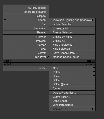
FIG 1.4 The quad menu.
The Quad Menu will give you access to most commands needed by clicking the RMB in a viewport. If there is no object selected, it will display generic commands seen in the right two quadrants of the image above. The two left quadrants will appear when an objected is selected, and as it is context-sensitive, the contents will vary depending on what’s selected.
The Quad Menu can be heavily customized, and it is worth looking into this further as you develop a workflow and get more experienced with 3ds Max. Max’s help section can provide further information on this if you are interested.
To begin with, we’ll start with some basic settings for 3ds Max. Go to Customize > Preferences > Files > Enable Auto Backup, and set the number of Auto Backup files to 9, and set Backup Interval (minutes) to 10, then click OK.
Next we’ll set up the units we’ll be modeling in; these vary from studio to studio, but in this book, one unit equals 1 cm. Go to Customize > Units setup … and, select Metric, and then click OK.
Don’t forget the in-depth help section is always at hand on the main menu or by pressing F1 or just log onto the free help forum at www.3d-for-games.com/forum and we’ll answer your questions as soon as you’ve registered and logged in.
I’d like to introduce you to the key terms used in the games industry relating to the creation of 3D assets. I am not going to go into great technical detail, as there are plenty of resources online which will explain these terms in greater depth. 3ds Max has a wealth of information in the help section, so don’t be afraid to use that F1 key to search for anything that you’d like to know more about. As you progress through this book, you will encounter all the elements listed below, clearly explained in context, and you’ll learn how to implement them.
3D geometry is made up of vertices, edges, triangles, and polygons. These are the elements that define the surface of a 3D model. We can manipulate each of these in 3ds Max.
Vertex (plural of vertices): A vertex is a single point. It contains information of its position in 3D space using the X, Y, and Z co-ordinates system found in 3ds Max. Vertices form the basic structure of geometric objects in 3D. Figure 1.5 shows a vertex on the corner of a cube.
Edge: An edge is a line that connects two vertices. The edge is highlighted in red in Fig. 1.6.
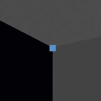
FIG 1.5
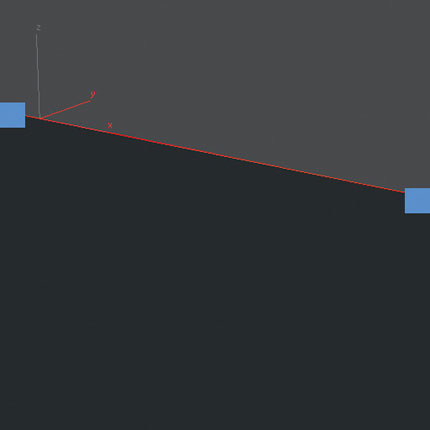
FIG 1.6
Triangle (face): A triangle is created when three vertices all have edges connecting them. In relation to a 3D model, a triangle is the surface between these three vertices/edges. It is this surface that defines the form of a model. Triangles could also be called faces as these usually have three sides. Figure 1.7 shows a triangle selected on the face of a cube.
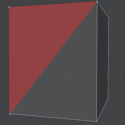
FIG 1.7
Polygon: A polygon is typically the surface between four vertices/edges. This could also be referred to as a quad. Polygons are also referred to as faces as they can have three or more sides. Polygons with more than four sides are referred to as n-gons. A quad consists of two triangles; you can see this in Fig. 1.8. On the left, I have selected a polygon on the side of the box which has two triangles counted in the selection. In the right of the image, I have selected an n-gon. Note it’s still counted as one polygon but three triangles or tri’s.
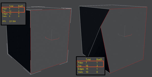
FIG 1.8
When creating 3D models for games, 99% of the time they should be made up of tri’s or quads. You can create a model with a mixture of triangles or quads or n-gons, but in the end, game engines and 3ds Max, all polygons are broken down into triangular faces. It’s good practice to measure your models complexity in triangles as this is more accurate.
Stitched Geometry and Floating or Intersecting Geometry
These terms refer to two techniques of constructing a model.
The first, “stitched geometry” or “stitched in geometry” is when every vertex in the model is connected to another creating a water-tight solid mesh. The example on the right of Fig. 1.9 is a cylinder sitting on top of a cube which is stitched to the cube at a vertex level. All of the faces that are not visible between these meshes have been deleted.
The example on the left of Fig. 1.9 where the cylinder sits on top of the cube is referred to as floating or intersecting geometry. Leaving geometry floating will mean that you use less triangles overall, but there is some overdraw in the face of the cube at the point where the cylinder sits over it. This surface area will be calculated in rendering, but it is never visible. The stitched in example has no unrendered surface area as it has been deleted during the stitching process.
The decision on which method is best can be determined by a game engine or a project’s needs. As a general rule and guide though small objects are ok to be placed on meshes as they cause little overdraw. Some examples are handles on doors, switches, posters, or fire alarms.
Large objects such as buildings connected to each other are best using the stitched method as the saving in overdraw is worth the extra triangles when the overdraw consists of a large surface area on screen.
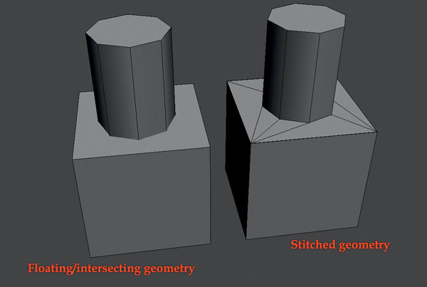
FIG 1.9
LOD is the acronym for Level of Detail. LODs are used in almost every game today. A LOD is a version of an asset which is lower in polygon count than the original. Sometimes, LODs have smaller texture maps or simpler shaders too.
For an artist creating LODs, you should aim to reduce the polygon detail to around 50% per LOD, more if possible without destroying the outline of the asset.
There will be a chapter discussing this topic in detail later. Figure 1.10 shows a model of an old fire extinguisher with two LODs and the polygon counts of each reduction.
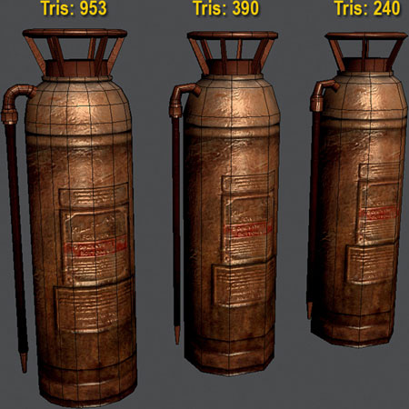
FIG 1.10 An old fire extinguisher.
The terms textures or texture maps in game art refer to 2D images that are projected onto or wrapped around a 3D mesh. We’ll discuss this more in the tutorials later on in this book.
These texture pages can be cropped from photographs, be hand painted, or created using a combination of both. The purpose of texture maps is to define an object’s surface, color, or texture and to visually describe any extra details that are not modeled in polygons.
Here is a brief description of the most common texture types.
Diffuse map: A diffuse map is the main texture applied to most 3D models. This texture should define a surface’s main color and detail. A good diffuse map should not have any directional lighting in it. The only lighting that should be present in this texture should be from an ambient light source as if it’s being lit evenly from all directions. This means that recesses in the texture will appear darker and raised element would be lighter. No shadows or highlights should be present in the texture.
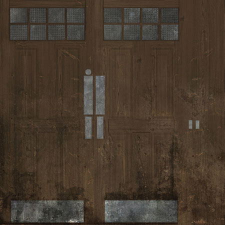
FIG 1.11 An example of a diffuse map.
Bump map: A bump map is a gray scale image, which affects the shading over a surface. A game engine or 3D program will interpret dark values as recessed areas and lighter values as being raised areas. Bump maps are used less frequently now because of other more advanced techniques like normal mapping.
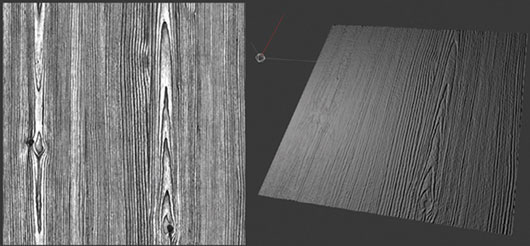
FIG 1.12 An example of a bump map.
Specular map: A specular map can be a gray scale or color image. Specular maps define a surface’s shininess and highlight color. If you use a gray scale specular map the lighter the value in the texture the shinier that area will be. Darker values will be less shiny with pure black resulting in a matte surface. A gray scale spec map will give you a white highlight. The example below is of a door. The metallic and glass surfaces are almost white, whereas the wood and dirt are much darker. You should be able to see the benefits of a specular map in the render.
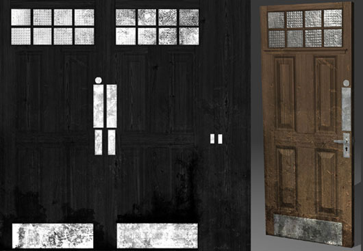
FIG 1.13 An example of a specular map.
Normal map: Normal maps have become a standard in most current games. A normal map is an RGB texture used to give an object the appearance it has a lot more detail than it really has. Each color channel contains information that represents the direction of a face’s surface normal in 3D space using the X, Y, and Z co-ordinates. This means normal maps work with dynamic lights and will light as if it were geometry. Normal maps can be generated from high resolution models or can be created from gray scale images. We’ll be discussing this in more depth later.
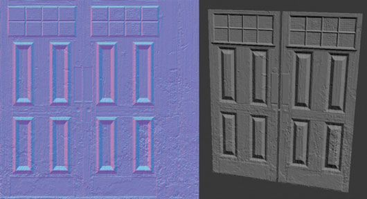
FIG 1.14 An example of a normal map.
Alpha map: An alpha map is a gray scale or black-and-white texture which controls the transparency on a surface. Black pixels appear transparent (or see-through) and white pixels appear opaque (or solid color). Common uses for alpha maps in games are leaves and foliage, wire mesh fencing, glass, cloth, decals, and particles. The example here is a small plant.
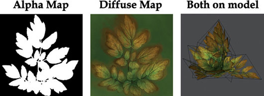
FIG 1.15 An example of an alpha map.
Shader: A shader or material in 3D is what we input all these textures into and then it’s applied to a model. A basic explanation for a shader is that it is a set of instructions for the GPU (general processing unit) or a mini program for the software telling it how to render a surface. Shaders can have a lot of parameters that we can adjust further to increase the effects of the assigned texture maps. We’ll be using 3ds Max’s material editors later in the book.
The space where we will layout our texture, the edit UVWs window has three axes just as the viewport does. They are referred to as UVW rather than XYZ. The U- and V-axes correspond to the X- and Y-axes. The W-axis corresponds to the Z-axis and is generally used for procedural maps. For now, we’ll be referring to the U- and V-axes.
A tiling texture is one that is seamless and can be repeated across a surface. It needs to be seamless in at least one or both of the U- and V-axes to work. The following image shows the different directions a tiling texture can tile in.
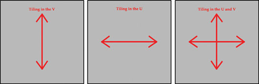
FIG 1.16
Tiling textures are commonly used in games to cover large surfaces or surfaces that do not require any unique details such as the ground, brick walls, or landscape. Here are some examples.
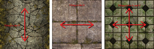
FIG 1.17
A unique texture is one that contains no tiling elements but many uniquely unwrapped UV shells laid out into the UV space. This type of map is commonly used for objects that require specific details or characters. Figure 1.18 is an example of a unique texture layout.
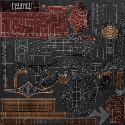
FIG 1.18 An example of a unique texture layout.
A Unique Texture with Tiling Elements
This type of texture layout utilizes both tiling elements which need to tile in at least one axis and uniquely unwrapped elements all laid out in the texture sheet. The following example has three strips running along the bottom of the texture sheet tiling in the U-axis. The top half of the texture is made up of several uniquely unwrapped elements.
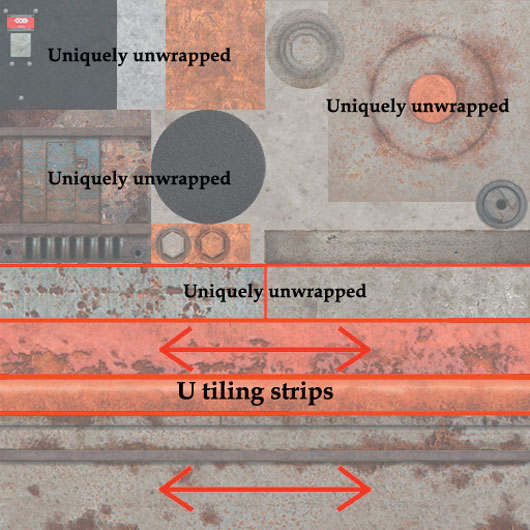
FIG 1.19
Think about how you will create your own texture pages in the future using these techniques.
This concludes our brief introduction to the most common terms used when creating art for video games. There are many more things to learn, and we will be dealing with some of these later in the book. It’s now time to start making some objects, so let’s move on to Chapter 2.