
Being a 3D character artist is an incredibly rewarding job—it’s great fun to turn your raw ideas into living, breathing beings, and there is always a challenge around the corner. To create photorealistic and believable characters, you must balance your 3D technical expertise with a sound knowledge of human and animal anatomy. Without a doubt, your most important asset is your “eye”; you must objectively scrutinize your creations at each stage of their development.
It is beyond the scope of this chapter to guide you through each and every one of the thousands of operations required to build this character. Instead, I would like to guide you through my working process, my way of thinking, and the tools I use. You need a competent working knowledge of 3ds Max, and you need to solve your own problems from time to time. This tutorial starts off fairly basic and gets into some more advanced concepts as we move along. If you get stuck on a problem with any particular tool, your best friends are the help menu (press F1) and Internet search engines. This is how I advanced my knowledge of 3ds Max once I had absorbed everything that the entry-level tutorials had to offer. As long as you make regular incremental saves (i.e., man01.max, man02.max, and so on), it’s pretty hard to break anything—so press all the buttons to see what they do!
The way we work, the tools we use, and the order in which we do things are known as our “pipeline.” I have refined my pipeline over many years to get things running as smoothly as possible.
Before we start the 3D work, let’s first plan out exactly what we will do. Once we know precisely what we will be creating, we will make a rough, low-polygon “proxy mesh” that will capture all the basic proportions and main shapes of the character. From this mesh, we will develop a high-polygon mesh that has all the little details that bring the character to life. We will apply UV co-ordinates to the high-resolution mesh and create realistic surfaces by applying a number of different textures to the surfaces of the character. We can use this high-polygon mesh for portfolios, advertising materials, in game cut scenes, and any other prerendered media.
Next, we will return to our low-polygon proxy mesh and optimize its level of detail so that it is suitable for real-time videogames. After we bake down all the details from our original high-polygon mesh onto this new low-polygon game mesh, you might be surprised how similar it looks to the high-polygon mesh. This mesh will be suitable for inclusion in any modern Sony Playstation 3, PC, or Microsoft Xbox 360 game, ready to be rigged and imported into the game engine.
Perhaps the most common beginner’s mistake is to rush headlong into modeling without sufficient planning. Modern video game characters can take more than five weeks of solid work to finish, so you don’t want to get to the end only to find out that the basic design is flawed. The best approach is to have everything drawn out in color before you start. Most studios will have at least one concept artist for this job, often recruiting specialist character artists to do the job. If you draw out your idea and it doesn’t work out, only hours or days are wasted—not weeks or months!
Often a good character starts with a simple thought, like “I’m going to make a tough-looking, futuristic commando,” but it is the concept process that will prove whether your idea works visually. As you draw out a detailed character concept, you are visually solving problems that might not have been apparent when it was just a rough idea in your head.
It is usually much quicker to experiment with designs on paper than it is to make a series of changes to your 3D model. Early in the concept phase, many fast and loose pieces are produced to try out as many different ideas as possible in a short period of time. Once the concept artist is happy with a final look for the character, he or she drafts up detailed blueprints to be scanned and colored on a computer. Using paint packages such as Photoshop makes it fast and easy to experiment with alternative colors, hairstyles, costumes, accessories, and so on. After the art director approves these concept designs, they are sent to the character artist for production.
Many character artists use a two-monitor setup; typically, one monitor is used for working in 3D applications and the other is used to display reference and concept images. This two-monitor setup works well; however, I recommend that you print out your most-used images and hang them on the wall near your desk. For the weeks that you will work on this character, you will save lots of time browsing folders looking for your reference and you will free up your precious RAM and processor resources for those greedy multimillion polygon meshes!
An Extensive Knowledge of Anatomy
If you’re serious about specializing as a concept artist or 3D character artist, you need an extensive knowledge of human anatomy. Even the most weird and wonderful alien characters will most likely have some similarities to us and your knowledge of human anatomy can add believability to your other-worldly creations.
The most intuitive way to learn anatomy is to spend a good amount of time in life-drawing classes studying direct from life, but it is essential to read up on your anatomy, too, unless you fancy cutting up some cadavers! Although there are many medical texts that will familiarize you with the inner workings of the human body, I’ve found it much easier to learn by reading artists’ guides to anatomy. Artist-specific guides are more relevant, as they concern themselves only with representing the main forms and the surfaces of the body, without getting too bogged down in the details. You don’t need to learn the names of each individual element, but it is essential to learn where all the major groups of muscles, tendons, bones, and areas of fat are in the body. It is quite common for beginners to focus on modeling all the muscles but forget about bony protrusions such as cheekbones, shoulder blades, and ankles. Your models will look formless and blobby without a good consideration of the bones that hold the body together.
The proportions of body parts in relationship to each other are of critical importance in character modeling; if you get the basic proportions wrong, your character will look terrible, even if you include loads of cool, small details. Small changes to proportions make a big difference in how people perceive your character—especially in the face, where tiny adjustments to the eyes can have a massive effect on the personality and mood of the character.
I heartily recommend the classic series of books about drawing the human figure by Andrew Loomis. The first editions are now out-of-print collector’s items, but you can find the books freely available for download on the Internet. Drawing Comics the Marvel Way by Stan Lee and John Buscema and the How to Draw Anime & Game Characters series by Tadashi Ozawa (Graphic-Sha) are also great, as they are very specific to the typical, idealized characters you often find in a contemporary game.
It may help to study classic artists such as Leonardo da Vinci. Leonardo shows in his art that there are many general proportional rules that loosely apply to almost everybody. Many of Leonardo’s works (and those of many other artists) make extensive use of the “golden ratio,” a number, known in mathematics as phi, that can be observed in many instances in nature. This number (approximately 1.6180339887) can be measured in the proportions of spirals in seashells, the length of bones in animals, and the distances between stems on plants. Look at the joints in your fingers; each successive joint is roughly 1.6 times longer than the last.
The ancient Greeks and Egyptians used the golden ratio in their classic architecture like the Parthenon and the pyramids. Modern studies have deemed these proportions to be esthetically pleasing and closely linked with our perceptions of beauty. You could even apply your knowledge of it to your own fantasy creature creations; it would be fair to hypothesize that if aliens do exist, they too might have evolved with “golden” proportions.
FIG 10.1
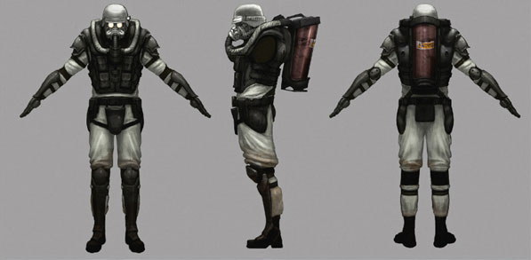
Upon receiving the “future commando” concept, our first job is to get to know him. As we want our character to be realistic and believable, let’s start by assuming that he is alive. Usually I ask the team and myself a number of questions, such as the following:
Q. Where does he live?
A. The scene is based in the United Kingdom; the reference was taken in an abandoned mental hospital in the Northwest of England. It’s not terribly important to tie the character to a location, but a Union Jack flag on his shoulder might be a nice detail.
Q. What material is his suit made out of?
A. He wears an NBC (Nuclear Biological Chemical) suit. The lightweight material is fairly tough, but flexible. The fabric has a charcoal layer in between the layers to protect him from nuclear fallout, gas, poison, or germ warfare. The fabric is unique: although it is flexible, it has a crisp quality and will hold creases. See if you can get your hands on an NBC suit in an army surplus store.
Q. Has he had any previous battles and have they left him with any damage to his suit?
A. Being on his hands and knees in various combat situations has left him with many surface scuffs and areas of ingrained dirt on his suit, but there is no real damage. His suit is his lifeline; it is replaced every six months, and if its function is compromised in any way, it is replaced immediately.
Q. What sort of soldier is he?
A. He is part of a specialist fighting unit, a real bad ass.
Q. What kind of gloves is he wearing? It is unclear on the concept sketch.
A. They are slash-resistant Kevlar gloves with lead lining. Perhaps it would be a good idea to extend the gloves to half-gauntlet size, to give better protection from his flamethrower.
Q. How old is he?
A. To become this tough, he must have been in various branches of the military for a number of years—he is in his early 30s.
Q. How old is his gun? What type of gun is it?
A. It is a flamethrower, maybe with a small shell launcher or other weapon on the bottom.
Before we get into the modeling, it’s mandatory to gather a wealth of reference material. You might think you know what things should look like, but reference photos always help you add that extra touch of authenticity. Detailed reference materials show you things about your subject material that you might have overlooked: the way it fades in the sun, the wear from children scratching their names into it, or the bits of chewing gum that get stuck to it. These observed details put your object into a real-world context and prevent it from looking unrealistically new or featureless. When it comes to the texturing stage, your reference will help you analyze the materials that make up your character—and you might be able to use a reference photo directly in your final textures.
For each object you research, it is advisable to get reference shots from as many different camera angles as possible. We need to know about every inch of the object’s surfaces; within your range of images, there should be no blind spots where important details are hidden. Don’t settle for just front, side, and back views. If you take the time to observe reference shots from the more obscure angles, such as the bottom, the back, and three-quarter views, it will add a professional level of depth to your models.
I use a Google image search for most of my research, set to “high-res images only” in the advanced settings. If this search is unsuccessful, I change the settings to medium- or small-size images. The Internet has a wealth of information, and there are many Web sites specific to whatever subjects you are researching. If you can’t find what you are looking for, try using alternative key words; use a thesaurus to come up with as many different names as possible for the thing that you are researching.
One of my favorite sites is www.3d.sk. For a subscription fee, you can download very high-resolution professional photographs of real humans—no airbrushed skin tones here! The library includes all shapes and sizes of humans: fat, thin, young, old, black, white, Asian, bearded, armored—pretty much whatever you might need as reference for your modeling. The images are all shot in scattered white studio light with no harsh shadows, which is perfect for use in your textures. The average subjects are normal everyday people, so you end up with lots of acne, spots, skin diseases, blemishes, moles, and birthmarks—all the things that add character to your creations!
You should make sure to have folders full of images concerning every aspect of what you are about to model.
Getting Ready to Start—Setting Up Image Planes
Image planes are used so that you can trace over the concept artwork inside 3ds Max to ensure that your model remains true to the original vision. I strongly recommend that you do not trace photos directly in the viewport, but instead use your reference as a reference—not as the blueprint for your model.

FIG 10.2
All photos are distorted by the camera’s lens, which exaggerates and warps the image. Wide-angle or “fish-eye” lenses like the one used in this page are an extreme example of lens distortion. If you study some catwalk fashion photography, you will notice that models are often shot from afar with a strong zoom lens to minimize the lens distortion effect. Ideally it is this type of photograph, if any, on which you should base your dimensions—but be warned that directly tracing warped images will lead to warped models. It’s better that you study proportions from life instead of relying on tracing.
To get a photograph with truly zero perspective distortion, you would have to be an infinite distance away from the object, with an infinitely powerful zoom lens just like the orthographic viewports in 3ds Max! Good concept artwork is drawn like this, with zero perspective, free from all lens distortion.
It is very important that the different views of the concept art are drawn out next to each other with ruled lines to ensure that the features match up accurately across the range of views. It can be very tricky to work from wonky and inaccurate concept art.
FIG 10.3
Starting to Build the Character
Let’s open the concept art in Photoshop now to prepare it for use in 3ds Max as the blueprint for our character. We need three square images for front, side, and back that line up perfectly with each other.
Use the rectangle selection tool while holding down the Shift key to make a precise square selection around the front view, and then copy and paste it into its own image file. Go back to the original concept art image again and use the right arrow key to nudge your square selection over to the side view. Copy and paste the side view into its own image file, then repeat the process for the back view. Our use of a nudged selection to produce our three images ensures that they will line up perfectly in 3ds Max. Save each of these three views as a separate jpeg file.

FIG 10.4
Rather than using 3ds Max’s Viewport Background functionality, I prefer creating the image planes myself as geometry. I find it easier to manipulate the scale and position of the blueprints if I just map images onto planes. If I want to scale or transform the model, it’s easy to include the image planes in the transformations and keep everything in sync.
Open up 3ds Max and create a square primitive plane (Create > Standard Primitives > Plane). It is important to hold Ctrl as you drag out the dimensions of the plane to ensure accurate square proportions like the images we prepared in Photoshop. Be sure that Generate Mapping Coords. is checked to save yourself the trouble of manually creating UV co-ordinates. Apply a Blinn material to this plane object, with 100% self-illumination and the ambient color set to white, and load the front concept image into the diffuse slot of the material. Now position the plane so that the character is centered on the origin (the center of the world co-ordinate system) with his feet directly above the origin.
Select the “front image plane” object that you have just created and rotate it 90°; my favorite way to do this is to hold Shift while rotating the object to copy and rotate the object in the same operation. Be sure to turn on the angle snap toggle button on the main toolbar to ensure an exact rotation of 90°.
![]()
FIG 10.5
Apply a new material to this new copied object and map the side concept image onto it to create the “side image plane.” Now copy/rotate the side image plane another 90° and apply another new material to it to create the “back image plane,” translating it back slightly to move it away from the front concept plane. The use of square images on square planes ensures undistorted and perfectly aligned features: no more messing around with translate, scale, and rotate trying to get everything to match up correctly.

FIG 10.6
Expert Mode, Hotkeys, and Scripting
Most modeling work involves a heavy amount of repetition, so it is more than worth your time to learn all the hotkeys for the major tools. If hotkeys are not assigned to your favorite tools by default, you can do it yourself using the Customize > Customize User Interface options. Sometimes, I write a script that performs a series of commands that I repeat again and again—it’s really not that hard to write basic scripts, so don’t be afraid to try it out yourself. Over the years, I have customized my workflow quite extensively to save me hours of repetition per day. Once you have made a couple of characters and want to save some time and energy, you should look at using scripting and hotkeys as a way of saving lots of time.

FIG 10.7
As I’ve been using 3ds Max for more than nine years, I’m very comfortable with the tools and my hotkeys for each modeling function that I use on a daily basis, so I don’t often use the icons. I usually run 3ds Max in Expert Mode (Views > Expert Mode), which keeps my interface free of clutter, giving me more room for looking at my character. If you are just starting out, you probably won’t want this, as it is good to explore the interface and each tool that is available, but it is a great option once you know exactly what you are doing.
As we are concerned with modeling, not animating, you can definitely turn off the track bar to save some room on your interface (Show UI ≥ Show Track Bar).
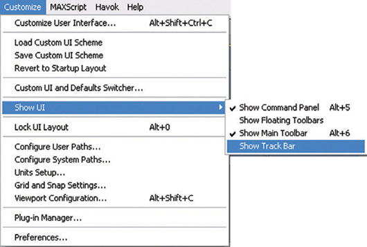
FIG 10.8
By default, 3ds Max’s viewports display rather low-resolution textures by today’s standards. If you select Customize > Preferences > Viewports > Configure Driver, you can increase the maximum texture size. Select “1024” and check “Match Bitmap Size as Closely as Possible” for both “Background Texture Size” and the “Download Texture Size.”

FIG 10.9
Getting the Basic Proportions Right
Let’s start the modeling with the classic starting point: the “primitive cube,” known in 3ds Max as the “box primitive.” Right-click your cube to convert it into an Editable Poly. We will make half the character initially. Press 4 to select polygon mode and the top polygon to select it. Now use the Extrude tool to extrude the polygon upward to make a chest, select the top poly on the left side of the shape and extrude out to make an arm, and select the bottom poly and extrude out to make a leg.

FIG 10.10
You might need to move the side image plane out of the way a little so that you can see what you are doing as our character widens. Ensure that you move it only by sliding the X transform handle; this way, we will not lose the vertical “registration” with the front and back concepts. Press 1 for Vertex mode and move all the object’s vertices into better positions to match the concept. It is easier to see what you’re doing if you apply a new material to our object, with 30% opacity and a strong red color.
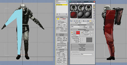
FIG 10.11
Next you should select the polys on the inside of the mesh, where the line of symmetry will go, and delete them. Press F4 to show the edged faces clearly.

FIG 10.12
Let’s mirror our mesh to make the full form—it would take twice as long to do everything if we didn’t use symmetry to our advantage. Activate the Affect Pivot Only button in the Pivot panel and move the pivot to the origin; be sure to deactivate the button after you have finished. Next, apply a Symmetry modifier; you might need to check the Flip box and then adjust the threshold slider until the center vertices snap together. We now have a full figure.

FIG 10.13
If you click on Editable Poly on the stack, the symmetry will disappear. You must press the “SHOW END RESULT ON/OFF TOGGLE” button (the little test tube under the stack); this will switch on all items further up the stack, which is invaluable for modeling with most modifiers. As we work, you can also switch on and off the light bulb icon next to the Symmetry modifier to turn its effect on and off.
Let’s add some more geometry to refine the shape. Select one of the horizontal edges running down the leg and press the Ring button, which selects all the parallel edges running down the leg. When the mesh gets more complex, the Ring and Loop select functions become invaluable for making quick, accurate selections. Next, hit the rollout box to the side of the Connect button in Edit Poly to connect these edges with new polys and select two segments.
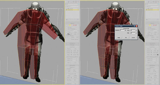
FIG 10.14
Repeat the select Edge, select Ring, and Connect process for the vertical edges running across the arm and the torso to increase the detail level further. Now spend some time moving these vertices around to fit the concept sketches.
The key to modeling fast is to add new geometry only as you need it. Before you add any new polys, make sure that the ones that are there already are well-placed; this reduces the amount of translating work you do substantially, as any new geometry you make will already be somewhat in the correct area. Create, refine, create, refine: our basic workflow.

FIG 10.15
Click the poly at the end of the arm and extrude it out to make a hand. Do the same at the end of the leg to make a foot.

FIG 10.16
Extrude out the poly at the front of the foot to make it more natural-looking and refine all the vertices of the hand and foot into better positions.
Now let’s add more geometry so that we can match the concept closer. Select Poly mode by pressing the 4 key, and then press Ctrl + A to select every poly on the model. We will turn every poly into four polys by pressing the Dialog Box button next to the Tessellate button in the Edit Poly rollout.

FIG 10.17

FIG 10.18
Now refine the vertices to match the concept shape better. If you like, you can change the opacity of the material a little to make it easier to see the concept underneath.

FIG 10.19
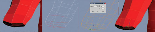
FIG 10.20
To make the fingers, connect the edges at the end of the hand to make four columns of polys.

FIG 10.21
One by one, extrude each column of two polys to form each finger.
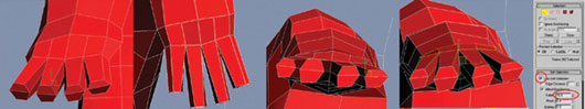
FIG 10.22
Refine the new vertices to make more natural finger shapes. I used Soft Selection with a larger Falloff setting to put a natural bend into the hand without having to move each point separately.

FIG 10.23
When moving vertices in the Perspective view, I find it useful to switch the co-ordinate system from View to Screen. Screen co-ordinates aren’t locked to the world x-, y-, z-axes like the View co-ordinates are, making fine adjustments in a Perspective view much quicker and more intuitive.
It’s important with nearly all models to keep a clean, quad-based topology. A pure quad mesh is much easier to “read,” and you can work faster using the Loop and Ring functions. It’s hard to see what’s going on if you use a lot of triangles in your mesh and they subdivide very unpredictably.
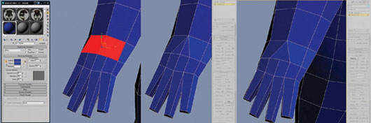
FIG 10.24
If you study the previous figure, you will notice that the two selected polygons have five vertices each; these faces with more than four vertices are called “Ngons.” Ngons are just as bad as triangles when subdividing; during rendering they are triangulated unpredictably, so it’s better that we turn them into quads. Use the Cut tool to cut some new edges as shown previously, and then select the center edge and use the Remove button to eradicate it. Do the same on the bottom of the hand, too, to rid our mesh of all the evil Ngons.

FIG 10.25
Let’s add more detail to the upper arms. Select and connect the top two rings of edges.

FIG 10.26
Work the forms into the mesh, adding new edge loops wherever you need more detail.

FIG 10.27
Add more edge loops to the legs and then shape the details. Try to model the edge loops along the main creases. Notice where I have angled the edge loops down to fit the shape of the kneepads.

FIG 10.28
Extrude out a head from the top center polygon, making sure to delete the polygon that the extrusion creates on the line of symmetry, and then Tessellate the head to add more detail.

FIG 10.29
Now that we have the basic character shapes, let’s cut in the medium-frequency details. These are the subshapes within each major shape, such as the main shape of each piece of armor, each strap, and the main flow of the fabrics. Add more geometry to the head, taking care to preserve a clean quad-based surface as you go. Try not to make tiny details in one area before you have cut in all the main shapes—keep the level of detail consistent across the mesh.
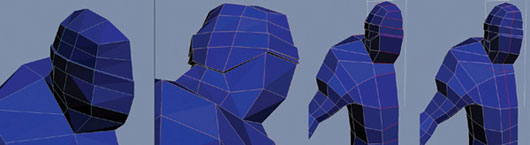
FIG 10.30
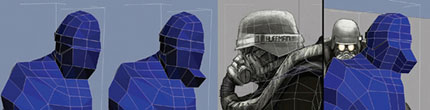
FIG 10.31
The flow of the edges is very important; our aim is to try to make all the edge loops join together in flowing and continuous lines. Good edge flow makes much smoother and more natural surfaces.

FIG 10.32

FIG 10.33
Notice the bad edge flow on the selected polygons in Fig. 10.33. There is a triangle in there, too, which isn’t ideal. If we add edges and rework the topology, we can create a more organized surface. Don’t expect the art of a perfect quad-based surface to come to you overnight, but with lots of practice, you will prevail. If you need some inspiration, visit some Internet forums and study other people’s meshes to see how they are arranging their edge flow.

FIG 10.34
A primitive cylinder makes a great starting point for the eye, as it is perfectly round. We must make efficient use of our polygons, so play with the parameters until you get a good balance between a nice model and a reasonable amount of geometry. I chose 12 sides and only one height segment. Convert the primitive into an Editable Poly when you are done, and remember to delete the backfacing polygons. A classic beginner’s mistake is to have loads of unnecessary polygons that are never seen because they are inside the mesh hidden by other polygons—don’t do it!
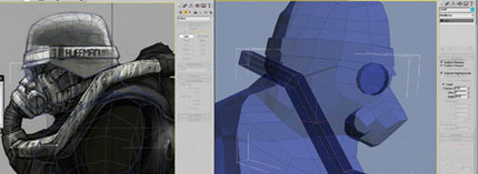
FIG 10.35
Another great starting point for your pipes, legs, and other twisty cylinders is the Line primitive in the Shapes section of the Create panel. First, draw out your line with a few simple vertices, and then in the Modify panel, enable the line in the renderer and viewport, generate Automatic Mapping Coords (saving you UVing time later), and play with many aspects of the topology on the fly. It’s easy, fast, and versatile, but best of all is that it creates very accurate meshes.

FIG 10.36
You can select and move the vertices in the Line, similar to how you would in Edit Poly by using the stack in the Modify panel. Once you get the vertices in the right place in each viewport, you can use the Refine tool to add more points to get the correct shape. Change the Sides parameter to give your line four sides and perhaps adjust the Angle setting, too. If you are happy with the shape, you can convert it into an Editable Poly. Before you do so, make a copy of the line and hide it—you can return to this hidden line if you want to make quick changes to the pipe topology later on.
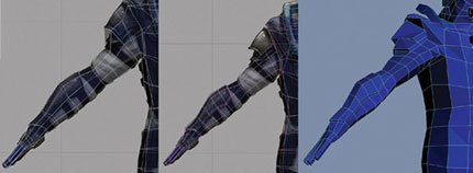
FIG 10.37
Once you have the main shapes and the edge flow working well on the arms, it’s time to start extruding the pads and the straps to block out the detail. Be careful that your extrusions do not create hidden polygons inside the main geometry. The Hide/Unhide Polygon tools in Edit Poly are your best friends when things start to get a little more complex.
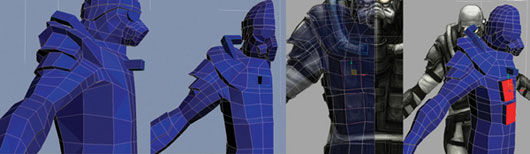
FIG 10.38
Remember to work on your model from as many angles as possible as you develop it. It will start to look flat if you use only the front and left views.

FIG 10.39
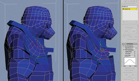
FIG 10.40
When meshes get more complex, it can be time consuming to make changes to the overall shape, so remember to use Soft Selection. Why move one vertex at a time when you can move hundreds together? Adjust the falloff and away you go.

FIG 10.41
A primitive cylinder makes a good start for the oxygen tank; another Line primitive does a great job for the central pipe on the mask.
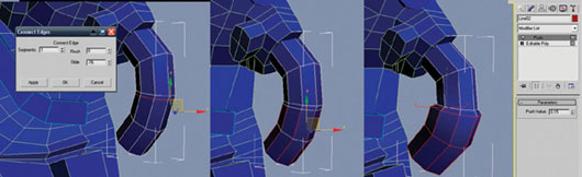
FIG 10.42
Select the line that makes the central pipe on the mask and convert it to an Editable Poly. Select the ring of edges where we want to increase the diameter of the pipe and connect the edges; use the Slide parameter to move it higher. Select the two lowest rings of edges below and apply a push modifier to flare out the pipe a little, and then collapse the stack back down to an Editable Poly.

FIG 10.43
Right-click on your pipe object, and choose Isolate Selection. This command is very useful when you want to see all sides of the object without other objects getting in the way. Delete the hidden faces at the top, and click the Exit Isolation Mode button.
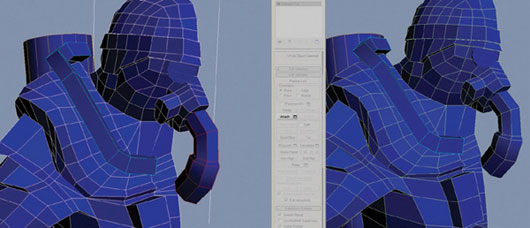
FIG 10.44
To add this pipe geometry to the main mesh, first delete the left-hand side of it so that it can be mirrored like the rest of the model. Select the main mesh, click the Attach button, and click the pipe.
Add some more geometry around the torso and under the arms. It’s important to visualize the body underneath the clothes as you mold your character. Imagine where the major muscles are sitting and how they are pushing on the clothes. It’s a good idea to look at the model from underneath quite often; if you make your model look correct from this often-overlooked view it helps make your model more accurate.

FIG 10.45
Start the hands by extruding a thumb, and cut in some more loops on the fingers to add a slight curve to each finger.

FIG 10.46
As you develop the hand/glove, it’s useful to have your reference by your side, so that you can copy the real-life hands/gloves as closely as possible. If you’re having trouble making your hand look correct, study your own hand. One of the most common beginner’s mistakes is to make the thumb bend like the fingers. The thumb should bend at 90° to the bend of the fingers. It’s also very important to build curvature into the palm.
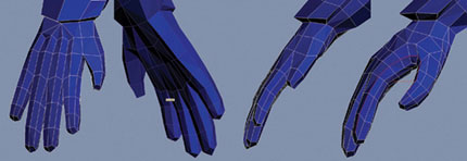
FIG 10.47
Let’s make the gaps between the fingers less angular and more natural; select the edges between each finger and chamfer them.

FIG 10.48
Cut some edges and weld (I like to use Target Weld) the rogue points together so that you get a topology something like Fig. 10.49. The aim is to get a smooth loop that flows around the rim of the glove. The glove isn’t perfect yet, but let’s move up the arm so that we keep an even amount of detail across the body.

FIG 10.49
Try to improve the look of the arm as much as you can without adding any more geometry. Once everything is in place, cut in more loops to define the straps and pads on his arms. Pay attention to the direction of the loops; they must follow the contours of the outfit.
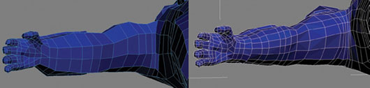
FIG 10.50
When modeling hard-to-reach places such as the cavity near the shoulder pads, you have a few secret weapons in your arsenal. It will be much easier to rotate around your selections if you activate Arc Rotate SubObject near the bottom right of the interface. You can flatten areas by selecting the relevant polygons and pressing the Make Planar button.

FIG 10.51
If you wish to smooth out a selection of polys, press the Relax button. Another top tip for being able to see what you are doing in difficult places is to hide some polygons. Press the Hide button to hide your selection of polys; Unhide All brings them back when you have finished.
Continue going around the body, looking at it from different angles and tightening things up. Be sure to study some reference material of a suitably tough-looking male, shot from as many different angles as possible. Good anatomical references help you build up the volumes of muscle, bone, flesh, and fat that lie underneath our character’s clothing. Again, working from the obscure top and bottom angles really helps give an extra “punch” to the forms.
At this point, you should have all the major shapes modeled in like shown in the following images. The total character at this point contains approximately 5000 triangles.
Once you are happy with the air pipes that you made with the Line primitive, you can convert them to an Editable Poly. The edges are a little sharp, so use the Chamfer function to round them out a little.
Continue to work more detail into the main lines of the mesh, using all our old favorites such as Cut, Move, Loop, Ring, Connect, Extrude, Relax, and so on.

FIG 10.52

FIG 10.53
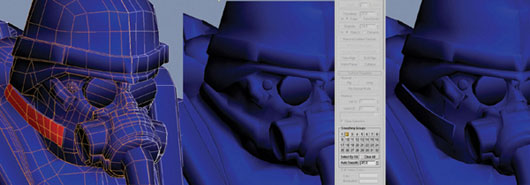
FIG 10.54
I find it easier to work with the mesh if I give each major group of polygons (kneepads, sole, glove, and so on) a different smoothing group; this allows me to better see the boundaries between different areas. A fast way to do this is to use the Auto Smooth button, but you might need to refine its work in places.
Keep adding details until your mesh is about 13,500 triangles; you can use the following images for rough reference. Don’t go crazy trying to match my model exactly, but the detail should be evenly spread throughout the body, with a slight emphasis on the face.
Make sure to save your mesh around this point. Although it isn’t detailed enough for our high-resolution mesh, it is certainly a good starting point for additional detail. Also, with a little tweaking, it will make an excellent game mesh when we load it back up later on. I call this mesh the “proxy mesh,” as mentioned earlier, because it is approximately the same form as both the game mesh and the high-resolution mesh.
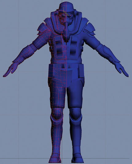
FIG 10.55

FIG 10.56
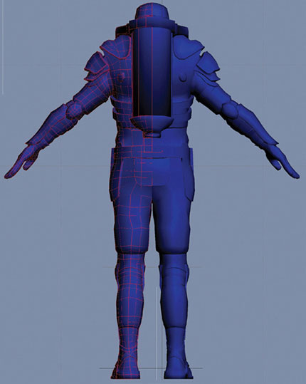
FIG 10.57
The High-Resolution Mesh: Breaking Up the Shapes
Now it is time to start the high-resolution modeling. As the level of detail increases, I find it much easier to work if we break up the mesh into each individual component. Select the polygons for each distinct part of the body and break them into separate meshes using the Detach button. Each mesh can then be isolated if you need to work on the hard-to-see areas.
If the separate parts of the mesh aren’t actually welded together, you can easily select them for detaching using the Element selection.
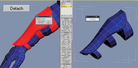
FIG 10.58

FIG 10.59
It’s very important to give even the thinnest shapes some amount of thickness. The quickest and also the most accurate way to do this is to apply the shell modifier and increase either the Inner Amount or Outer Amount parameter. You might want to delete some of the polygons on the inside, as they won’t be seen.
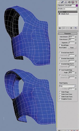
FIG 10.60
The High-Resolution Mesh: Adding More Detail
As you add all the subshapes that make up each piece of the character, you should not need any other tools than the ones we’ve used already. Just study the concept and the reference material very carefully as you work. Be careful not to get into too much detail in any one area of the character. The aim is to roughly mark in all the shapes until you get to about the level of detail in the following images:
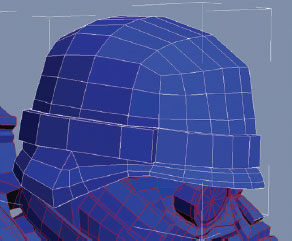
FIG 10.61

FIG 10.62
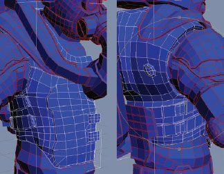
FIG 10.63

FIG 10.64

FIG 10.65

FIG 10.66

FIG 10.67

FIG 10.68

FIG 10.69

FIG 10.70
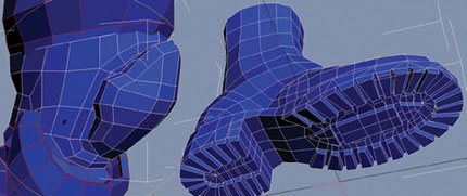
FIG 10.71
Most importantly, the chemical suit is modeled underneath everything. This will make sure that there are no gaps left in our mesh. A common beginner’s mesh will have lots of holes in it where the various meshes meet, and this is a great way to avoid that. Don’t model any creases or folds yet; we will tackle that later.

FIG 10.72.
An accurate and super-fast way to make the breathing pipe is to use the Loft compound object. Delete the old breathing pipe and in the side view, draw out a rough spline using the Line primitive. I’ve indicated on Fig. 10.73 the three clicks that I made to draw the line. Be sure to hold the left mouse button down as you drag out each point so that you can control the shape of the line as you create it.

FIG 10.73
If your line is anything like mine, it still looks a little wonky! Go into the Modify panel, select Vertex, and then click on each point and adjust the handles to get a good, smooth line. Also check that your line is correctly positioned in 3D space; it should be centered on the symmetry line of the model. We will call this line the Path of our loft, and it gives the shape to the length of the object.
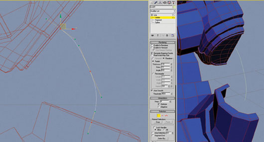
FIG 10.74
Let’s draw the shape of the Profile curve that will give the volume to our Path line. For this, we will use a circle primitive from the Splines rollout. Drag out the circle from the top view and scale and position it at the top of the Path curve. Take care to not rotate it.
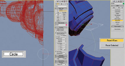
FIG 10.75
The next step is to reset the Xform of these two splines. Reset Xform resets the translation, scale, and rotation information back to how they were when the object was created. Having “zeroed out” transform values is critical for operations such as lofting that rely on this information. Reset Xform can be found in the Utility panel; with each of the two loft curves selected, press the Reset Selected button.

FIG 10.76
Select the Path shape and execute the Loft command, which is hidden in the Create panel’s Geometry section (select “Compound objects” from the drop-down menu). Click on the Get Shape button, and then in the viewport, select the Profile circle, and 3ds Max should create a basic Loft shape.

FIG 10.77
We have the basic shape looking pretty good now, but the real power of Loft shapes comes with the Deformation controls. Let’s use the Scale deformer to add the ribbed details to the surface. At the bottom of your new Loft object’s modifier panel, click on the Scale Deformation button. Adjust the graph that pops up so that it is long and thin as shown in the previous image. You might find that the zoom extends the horizontal button—useful for framing the graph correctly in the window.
Select the Insert Bezier Point button from the Scale Deformation interface.

FIG 10.78
With the Insert Bezier Point tool active, click on the red line to add a Bezier point at roughly every four units along the X Axis, across the line; your line should look something like Fig. 10.79.
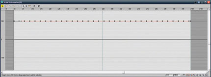
FIG 10.79
With the Move Control Point tool active, select any one point on the graph. You can see the xy co-ordinate of the selected point in the bottom right-hand area of the Scale Deformation window.
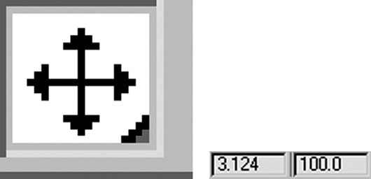
FIG 10.80
The “x” represents how far along the Path we are, and “y” represents the scale (which is constant at 1 the whole way across, at the moment). To get our ribbed details spaced apart with precision, let’s type in an exact number into the left-hand “x” co-ordinate box for each point. Here, your knowledge of your “3” multiplication tables will pay dividends! Repeat after me: 3, 6, 9, 12, 15, 18, 21, 24 … 96, 99.
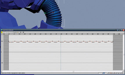
FIG 10.81
To create the bumps in the ribbed surface, select every other vertex (i.e., the ones at 3, 9, 12, 18, and so on), and in the “y” co-ordinate box, type in 90. Boom! The details appear. Open the Modifier panel and check the Generate Mapping co-ordinates option, which will save us time when generating UVs later.

FIG 10.82
Subdividing Your Model with TurboSmooth
The mesh is getting pretty detailed now, but it would take an eternity to keep adding geometry until we lose the harsh, angular look. This is where the TurboSmooth modifier comes in very handy.
Each iteration of TurboSmooth subdivides each polygon into four smaller polygons, relaxing them at the same time. Similar technologies exist in all major 3D applications. These types of surfaces are generally known as “subdivisional surfaces,” or SUBDs for short.
The key advantage to using TurboSmooth is that we can make fast changes to a simple poly mesh and not get bogged down tweaking millions of vertices to make a smooth curve. This smoothness is also the biggest drawback; at times it can be very tricky to preserve areas of the model that require sharp edges.

FIG 10.83
Let’s start our smoothing process with one of the simplest objects, the lens of the goggle in the mask. Select just your eye geometry and detach it to create a separate mesh.
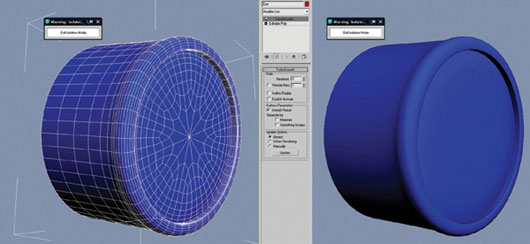
FIG 10.84
Apply a TurboSmooth modifier and push the iterations up to 2. As you dial up the iterations, the circular form of the eye gets rounded nicely, but we lose the crisp edges on the corners.

FIG 10.85
We can see the TurboSmooth effect most clearly by studying the side profile. TurboSmooth works by averaging out the positions of the vertices; those that are far apart from each other get moved quite substantially, and not always to your advantage. If you build your models with vertices closer together in areas with drastic changes of shape (sharp edges), they will be less dramatically affected when TurboSmoothed.
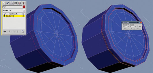
FIG 10.86
Go down the object stack and select Editable Poly. Select all the corner edges that you would like to sharpen up using the Loop tool. Chamfer these edges so that you get a nice corner bevel on each edge; I used the setting 0.012 for the chamfer amount, but this will vary depending on the scale of your scene. Select two segments for each chamfer.
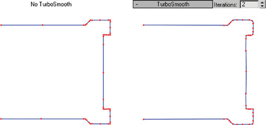
FIG 10.87
Your cylinder should look something similar to this figure from the side profile; the extra geometry locks into place the effect of the smoothing.
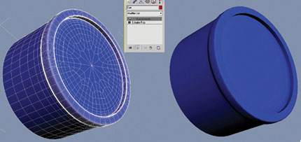
FIG 10.88
The results should be like the previous image: a perfectly round cylinder with hard edges at the corners. This technique is dubbed “microbeveling” in the industry because sometimes the detail you must put in on an awkward corner area gets pretty tiny.
If you build your models with nice, orderly quads, it is very fast and easy to add microbevels by selecting loops and chamfering them. Another advantage of doing your modeling operations on loop selections is that it keeps everything uniform across the edge. Most machined, inorganic forms like this goggle lens are made on a production line in a factory and, as such, are very regular shapes. Unless you want this type of shape to look worn or old, you should try to avoid going in and hand-tweaking individual vertices; it will lead to irregularities that make them look hand-made. Instead, do your inorganic modeling using modifiers and operations on loop-based selections.
The really tricky SUBD stuff comes when we have edges on more than one axis coming together. For example, take the edges of sole of the shoe where the tread pattern might involve beveled edges meeting on all three axes at many corner points. The simple solution is to do all your chamfering at the same time.
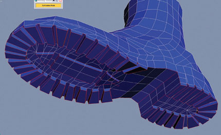
FIG 10.89
First, select all the edges that you would like to perform the chamfer on.
Then use the Chamfer button and tweak the amount to control the roundness of the edges.

FIG 10.90
This way is much faster and cleaner than doing your beveling one piece at a time. If you select some edges, chamfer them, and then repeat the process for other nearby edges, things quickly get messy. If we perform the chamfer operation to all the edges at the same time, we create a relatively orderly and even topology.

FIG 10.91
The last thing to do is to go through the mesh and reorder the topology to get the nice and clean square-quads look that characterizes a high-quality SUBD mesh. I’ve detached the sole from the shoe to help keep things simple.

FIG 10.92
Finishing the Symmetrical Details
One by one, work through your objects, adding TurboSmoothing, refining the details, and taking special care with the details of sharp and beveled edges. Avoid creating any asymmetrical details (such as the creases and folds of his trousers); we will tackle these details later on.
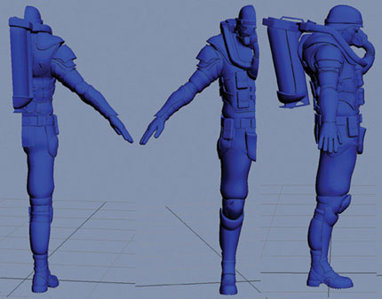
FIG 10.93
Your mesh should now look something like the previous image, with everything apart from the asymmetrical folds and creases of the clothing modeled in fine detail. Once you are happy with your half-character, give it another quick check for holes and other defects. It’s much quicker to fix things now, before we copy the mesh across the central line of symmetry and create a right side and a left side that both need identical repair work.
In 3D modeling, it is always beneficial to use symmetry to your advantage. If you take care to get things as good as you can before you mirror them, it will make your modeling almost twice as fast.
In order to get a texture onto our high-resolution model, we need to give it UV co-ordinates. This procedure can be time consuming and, dare I say it, tedious and boring! Typical high-resolution meshes have polygon counts measured in the millions, so we need every trick in the book to get these UVs done well in a reasonable amount of time. 3ds Max has some fairly good UVing tools for production like the Pelt Mapper and the Relax function, but I’ve found a small program called UVlayout to be far superior when generating UVs for complex high-resolution shapes. UVlayout optimizes your UVs for subdivision, considering how the UVs will be stretched when subdivided.
The UVlayout interface is not very pretty or intuitive, but if you watch the tutorial videos available for download from www.uvlayout.com, you will see just how amazing the program is. So don’t judge this book by its cover! In my experience, unwrapping in UVlayout is more than twice as fast as unwrapping in 3ds Max, Maya, or XSI. The quality of UVs that UVlayout produces is also much higher. The distortion-free UVs generated by UVlayout will save us lots of time and prevent frustration later when we come to texture this object. A trial version of this software is available from the download under Chapter 10UVlayout.
To keep things simple, we will import and unwrap each part of the character one piece at a time in UVlayout, so export each part as a separate Wavefront (.OBJ) file from 3ds Max (File > Export Selected). You should now have a list of objects organized in a UVing folder (such as belt.obj, boots.obj, vest.obj, and so on).
In UVlayout, click the blue Load button and browse to your UVing folder where you saved all the OBJ files. Load kneepad.obj first; it’s a simple object that will make a nice introduction to UVlayout. Remember to check your Load Options before you load the mesh; UVlayout will take the effect of the TurboSmooth SUBD’s into account if you select Type “SUBD.” Be sure to select the UV’s “New” button too, which deletes any old UVs that might be already applied to your object. Check the Weld UV’s and Clean boxes to ensure a tidy mesh, and then, with the correct object highlighted in blue, click the green Load button.

FIG 10.94

FIG 10.95
The first thing that you might notice is that your kneepads are being viewed from below. Open the Display panel and select “Y” to change UVlayout’s co-ordinate system. If you hold the Alt key, you can navigate in the 3D scene using the left mouse button to orbit, the middle mouse button to pan, and the right mouse button to zoom in and out. In the Display section of the interface, there are three different types of views, which you can select quickly using the 1, 2, and 3 keys:
• UV view shows in 2D your unwrapped UV co-ordinates.
• Ed or Edit view shows in 3D only your objects that currently have no UVs assigned yet.
• 3D view shows the original 3D object intact.
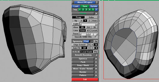
FIG 10.96
When you load the kneecap object into UVlayout, the default view is the Edit view. As you selected NEW when loading the object, it will have no UVs, and therefore its surface should be gray. If you move the mouse cursor over the main plastic kneecap shape at the front of the object and press D, the kneecap will disappear. The shape has not been deleted; instead, UVs have been assigned to it, so it is not shown in the Ed view anymore. Press 1 to jump to UV view and locate your kneecap UVs, which should still be a gray color, as they are not flattened out yet.

FIG 10.97
While you are still in the UV view, hold your mouse cursor over the kneecap UVs, hold the spacebar, and press F. Watch with joy as the UVs unfold themselves in a weird and wonderful way. Colors appear on the UVs now: red represents areas that do not have their fair share of UV space and blue represents areas that have too much UV space. Both red and blue areas show distortion, and we must seek to minimize that. If you press 3 to jump to the 3D view, you can see the colors now applied to the kneecap, showing in 3D space where the distortion is occurring.
Let’s help the UV shell relax a little more by making some cuts; cuts in the correct places will help our geometry unwrap. For most “closed” objects, cuts are mandatory—anything circular like a cylinder or sphere needs at least one major cut in order to be able to unwrap at all. I like to think about unwrapping similar to how a primitive Stone Age hunter might skin an animal to make a cave jacket. A less gory analogy is to compare your final layout of UVs to how a tailor cuts shapes from a blank piece of fabric to make a garment.
Like the seams that a tailor deals with, cutting up your shell generates UV seams in UVlayout. The UV seams are a necessary evil that you must minimize. These could cause problems later if you want to paint your textures quickly and easily in Photoshop. You will need a 3D paint program such as ZBrush or Bodypaint in order to be able to paint continuous textures over seam areas. Furthermore, each UV seam can cause problems further down the line with normal mapping.

FIG 10.98
Press 1 to jump back to the UV view and then zoom into the top half of the kneecap UVs so that you can clearly see the details of each edge. With the mouse hovering over the relevant edges, press the C key a number of times to make cuts as shown above. Remember that the first cut you make must start from an open edge on the outside boundary of the shell; you cannot start your cuts from the middle of the shell. If you make a mistake, you can weld your cut edges back together by hovering over them and pressing the W key. With the mouse cursor hovering over the object, hold the spacebar again, and press F to unfold the object once more. It should be able to relax much better now with the new cuts, giving you a new relatively distortion-free unwrap.

FIG 10.99
In Edit mode, the C and W keys have extended powers, in that they work well with loop-based topology—another great reason to model in clean quads as much as you can. As UV seams hinder our texturing, we must hide them away, thinking carefully about their placement before we draw them.
On character legs, the most unseen areas are the inside surfaces—they are normally hidden by the opposite leg. Go to the inside leg side of the “kneepad elastic” shape, and press the C key on one of the vertical edges. Your “cut” edge is marked in red. UVlayout will try to predict how you would like to continue the cuts along the loop with lines marked in yellow. If you disagree with any of these yellow lines, you can weld them back together with W. It takes only two or three clicks with C and you should have made enough cuts to unfold this area successfully.

FIG 10.100
As we are dealing with a “closed” shape, before we drop the shell into UV space, we need to “split” the cut edges. Hold your mouse over the red and yellow edges that you wish to split and press Shift + S to use the Split Seams command. The edges should split apart like in the previous example.

FIG 10.101
Now you can press D on this mesh to drop it into UV space, press 1 to go back to the UV view, and then unflatten it as shown in Fig. 10.102.

FIG 10.102
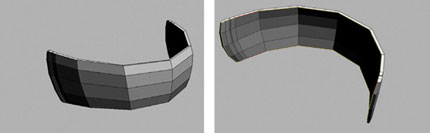
FIG 10.103
Press 2 to jump to Edit view, and you will see that there is now just the strap which doesn’t have UVs. Use the C key to make cuts until you have a closed loop of cuts going around in a circle. As always, it is best to hide the seam on the inside surface of the strap where it won’t be seen clearly; you will get an intuitive feel for where to place seams after spending plenty of time unwrapping various objects.

FIG 10.104
Again, press Shift + S to split the seams, and then press D to drop each piece into the UV mode. Press 1 to go back to UV view and unflatten each piece.
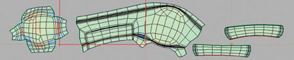
FIG 10.105
If you press W on a few of the shared edges of these two straps, you can see the matching edges turn red to indicate that it is possible to weld them back together. Press Return on one of these shells once you’ve marked some red weld lines and UVlayout will join them back together. Unflatten the shells again to finish and save your work.
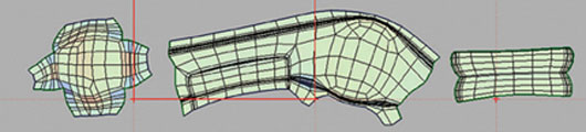
FIG 10.106
For anyone from the old school of UV unwrapping, UVlayout is nothing short of a revolution. It would take me days to unwrap a simple 1000-poly character in 3ds Max 3 with the Unwrap modifier; the same job now takes less than an hour, and I get much better results, too. UVlayout is incredibly powerful software, but I can’t hope to cover all the cool features like pinning UVs, straightening UVs, and auto-packing UVs in this chapter. If you want an easy life with UVs, you would be wise to watch all the tutorial videos posted on the UVlayout Web site.
It’s essential to unwrap our half-character before we mirror over our character; this precaution will make things go almost twice as fast. Once you are happy with your half-character unwrapped, you can add a Symmetry modifier to the mesh, collapse the stack, and then select and flip the UVs from one side to the other. It is then a simple job to weld the left and right halves together to get rid of any unnecessary seams. When arranging my UVs, I start with the largest shapes first; the smaller shapes will fit in the gaps once you have the main shapes in place. Try not to waste big areas of space in your UVlayout because in video games memory is critical and shouldn’t be frittered away on half-empty maps.

FIG 10.107
I like to lay out my UVs in a meaningful arrangement, with the head at the top and the feet at the bottom, arranged as if the character is looking straight at you. If you pass your work through a production pipeline, anyone who has to pick up your work and make some tweaks to the texture will thank you for making the texture layout as readable as possible.
The Asymmetrical Details: Making the Folds and Creases
It is now very common in professional modeling production pipelines for two or more apps to be used, as each application offers its unique advantages. More and more studios are turning to ZBrush to make the organic shapes that characterize the folds and creases that occur on clothing and anatomy. ZBrush can make the process of organic detailing quick and easy, but as this book focuses on 3ds Max, we are going to make the folds the old way: with SUBD surfaces. Traditional SUBDs take longer to produce, but one benefit will be the efficient use of polygons and system resources. Our 3ds Max clothing will be perhaps 10 times lighter (very high-poly assets are described as “heavy” in industry jargon) than a typical garment detailed in ZBrush, and it is good practice for making flowing SUBD geometry.
On the concept that I have been given, the creases are symmetrical—probably a measure taken by the concept artist to shave some hours off his or her busy schedule. Copying this symmetry into the 3D model is not good for realism, as the creases in all clothing are asymmetrical. Knowing when to follow the concept and when to correct it is very important. Keep a sharp, critical eye on your work so that the mistakes of the concept artist don’t get transferred to your models.

FIG 10.108
As the creases and folds of the fabrics can take a couple of days to model in SUBDs, I’ve sketched out a quick plan for my creases first. This way, if I don’t like the flow of the creases, I can quickly amend them in minutes not hours.
When modeling organic shapes like the creases, it is critical that each curve flows smoothly into the next; look for unnaturally straight lines and eliminate them. Use Relax to melt the polygons into each other. It makes sense to assign a hotkey to the Relax button, as you should constantly use it.
Take care that your creases don’t all point in one direction; study some photos of people in clothing, and you will see the multilateral qualities that creases take on as they try to conform to the shape of the body.
If you use Relax multiple times and the geometry still looks jagged and awkward, the problem is probably your edge flow. Put your mesh in wireframe and adjust any areas where the edges don’t run together in nice smooth lines.
Gravity, Tension, and the Feel of the Fabric
Be aware of gravity and how it affects your garments: baggy areas sag, but areas supported by the body remain firm. Imagining the body underneath the clothing is very important. Be aware that protruding parts of the body, belts, and straps pull on the fabric creating areas of tension. I keep lots of reference of the material that I’m modeling handy as I work to make sure that my model has the same look and feel as the fabric that I’m trying to mimic.

FIG 10.109
To start, just model in all the major creases of the body without too much care for the topology. Try to get the edge loops pointing in the same direction as the flow of the fabric for now—it should look something like Fig. 10.110. I have isolated the mesh for better system performance, but for many areas, it’s important to view the rest of the character as you create an NBC suit so that you can really get the feeling of the suit material bunching up in areas where it is restricted by the pads and elastics straps on top of it.
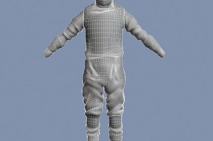
FIG 10.110
Once you have cut in the basic shape of each and every crease and fold, you can add additional details to refine each part. When all the details have been modeled in, it is just a matter of reflowing the topology to eliminate any awkward areas that don’t look so smooth and natural. It is good to preview your suit all smoothed out with the TurboSmooth modifier at regular intervals so that you can see how it will look when it is finished.
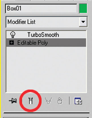
FIG 10.111
Bear in mind that although it is possible to model on the Editable Poly with the TurboSmooth showing further up the stack (using the Show End Result toggle), in the industry, it is generally considered bad practice. Meshes created in SUBD mode like this quickly get messy and tangled up, and they are very confusing to work with if you have to drop back down to the Edit Poly level to make a change. With SUBDs, experience is the best teacher; a few projects down the line, you will be able to accurately predict how your meshes will subdivide. Don’t rely on TurboSmooth to create a smooth mesh for you—it’s only as good as the base mesh that you feed into it.
Once you’ve finished adding all the creases, reflatten your NBC suit UVs in UVlayout and make any final tweaks to the layout. It’s important to get the UVs as distortion-free as possible to make life easier when texturing.
Ambient occlusion (AO) maps are an industry-standard method of baking subtle lighting information into models. AO maps describe how exposed each part of the surface is: the cracks and gaps hidden away in cavities receive very little light and render in dark tones, and the flat, exposed surfaces render in light tones. An AO’s soft, scattered light adds a great feeling of depth to your creations. I find it very useful when finishing off my model to render an AO map and apply it to the model. Rendering AO maps in 3ds Max is very simple:
• Apply a white Phong material to your character.
• Go to the Lights creation panel and select Skylight. Click to create a Skylight anywhere in the scene. The placement is not important; anywhere will do.
• Select Render > Advanced Lighting > Light Tracer. Be sure that the “Light Tracer Active” box is checked.
• With the character object selected, click Rendering > Render To Texture.
• Choose an output path for the AO map. Be sure that this render will use the Existing (UV) channel.
• Add a CompleteMap render element. Choose a map size of 2048 × 2048.
• Hit Render and watch as 3ds Max calculates the AO and renders it to a texture.
• Apply the newly created AO map to the diffuse map slot in the character’s material and set the diffuse color to white.

FIG 10.112

FIG 10.113
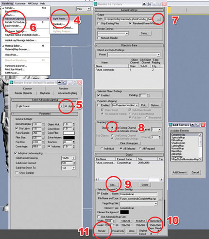
FIG 10.114

FIG 10.115

FIG 10.116
With AO applied to the model, it is a lot easier to see where all the overlapping geometry, holes, and other UV errors are occurring.
If you get areas that have rendered with weird-looking patterns on them, the chances are that you have overlapping UVs. Apply the Unwrap UVW modifier and make sure that all the UVs have their own space; get rid of all the overlapping UVs.
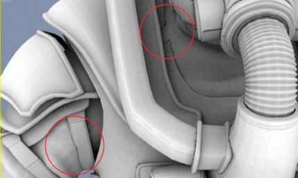
FIG 10.117
AO helps me a lot when fixing overlapping areas, as it really highlights anything that’s not right. Have a quick look over your model to see if you have any problems with intersecting geometry.
Once you’ve fixed all these problems, you can render the ambient occlusion map again; if there are still problems, repeat the process until you are entirely happy with the model and the UVs.
So you think you’ve finished the modeling? I ask you to take another detailed look at your model—you will probably find some mistakes. Perhaps wait a day and come back to your work with fresh eyes. I know some artists who like to flip their work upside down or mirror it horizontally when reviewing their work, as this can give you a different perspective on that model you’ve been staring at it nonstop for more than three weeks! I like to squint my eyes when looking at the overall proportions, which blurs out the details and leaves me to focus on analyzing just the basic colors and shapes.
Art is subjective, and it is important to note that no artist is perfect; this is why getting other people’s opinions of your work is very important. If you have no immediate group of peers, Internet forums can be an important place to get constructive criticism of your work. Good constructive criticism offers ideas for improvement of your work and does not dwell on the mistakes, apart from as a positive way of improving your work.
People make mistakes. This is why the work of companies is often (but not always) superior to the work of individuals, more eyes checking for mistakes—too many cooks don’t always spoil the broth! Get opinions from your friends; maybe even your family can help you spot weak areas that need improvement. Everyone is an expert when it comes to looking at people and even your little sister might be able to spot something that you overlooked, like a nose that is too big or legs that are too small.
On my first check of the model, I noticed and fixed lots of little gaps between the objects and added the bumpy creases to the two breathing pipes leading to the mask. I also tweaked a few of the folds on the NBC suit to make them look more natural. On my second pass around the character, I moved the head back and the shoulders forward a little, as his head looked too far forward on the concept. To make the gloves look used, I added some creases and bumps to the gloves. On my third check of the character, I noticed a big gap under the shoulder pads, so I built some geometry to act as the inner padding.
The following figure shows the final high-resolution model.
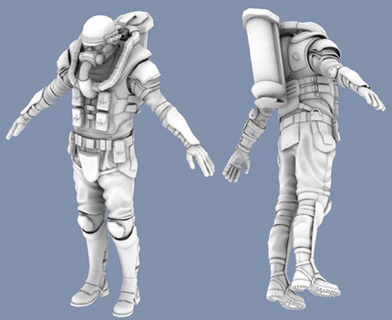
FIG 10.118
The texturing process can really put strains on your system, and in particular your RAM, which holds all the texture information in temporary memory. During the texturing process, I sometimes need to use from two to five applications at the same time, which can really stretch the multitasking capabilities of your machine to the limit. If you encounter long periods of down time as you swap applications or perform operations, you probably don’t have enough RAM.
To compound the RAM problems during the texturing process, I will be working with a rather large 4 KB (4096 × 4096-pixel) PSD file, even though the final textures will be only 2 KB (2048 × 2048 pixels). Working like this with a higher resolution PSD file ensures that your final textures won’t lose clarity after you have resized, warped, and liquefied them several times. Another advantage is that you can use the full 4 K maps for detailed close-up renders of your character—this will win you the dream job for sure!
I recommend a bare minimum of 2048 MB (2k) of RAM in your system, especially on the RAM-greedy Microsoft Windows Vista. There is really no such thing as too much RAM when working in the CGI industry. If you have problems, you could consider networking your desktop to another computer, like a laptop, which you could use beside your desktop computer to run Photoshop and create the textures, freeing up your main system’s RAM for the demands of 3ds Max. If you really have problems with texturing on your system, you might want to halve the dimensions of all the textures I use during this chapter; this will make the texture size four times smaller. Instead of previewing my textures in large, uncompressed TIF format, as some people recommend, I prefer to use high-quality JPEGs to save on RAM.
Today’s 32-bit operating systems like Windows XP Home Edition register a maximum of only 3.2 GB of RAM; any more than this is wasted, as the 32-bit OS will just ignore it. An emerging solution to your RAM woes is to use one of the new 64-bit operating systems like Vista 64 or XP 64, which theoretically work with up to 16 exabytes of RAM! That’s more than enough for your needs.
Let’s get some colors on the model now. We could paint them on in Photoshop, but I prefer to apply the colors in 3ds Max and bake them onto the texture. Baking the colors is much faster and usually better quality as you don’t have to do any fiddly paintwork in Photoshop. Painting the color texture by hand in Photoshop can be time consuming and problematic, as it can be hard to work out what’s what in the confusing sprawl of UV shells. I find it much easier to apply the base colors if I assign them to different selections of polygons in 3D, where I can preview the results in real time. What really makes the baking method a winner is that each baked color will generate a coverage alpha channel, which we can use to quickly select and tweak different materials inside Photoshop.
I have identified 13 different materials on the character: gray steel, self-illuminated lights, black leather, dark gray Kevlar, elasticized straps, painted steel on the oxygen tank, black plastic, dark cloth, fire retardant piping, rubber-soled shoes, gray plastic mask, black rubber, and NBC suit.
Break up your model into 13 corresponding pieces using the Detach and Attach buttons in Edit Poly. Each object that you create should be assigned a different colored material. The colors are not important; we will throw them away later. I’ve used crazy colors just to help myself differentiate between the various types of surface.
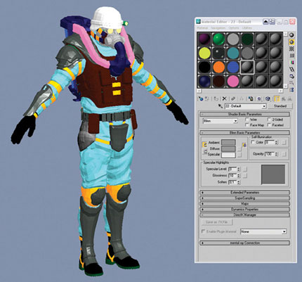
FIG 10.119
Once you are happy with the material groups, bake these different surfaces onto the texture using the Rendering, Render To Texture dialog. For each object, repeat this process:
• Choose the output path and give each file a descriptive name, such as Gray Steel.
• Be sure that “Use Existing Channel” is selected, as it would be a shame to waste those lovingly crafted UVs!
• Add a DiffuseMap output.
• Choose a 4096 × 4096 texture size (4k).
• Hit render.

FIG 10.120
If you open up the black leather texture, it’s just a black square because we rendered a black material onto a black background! Open up the Channels window, though, and go to the alpha channel to see that we have a map that describes perfectly which areas on our UV sheet are black leather.
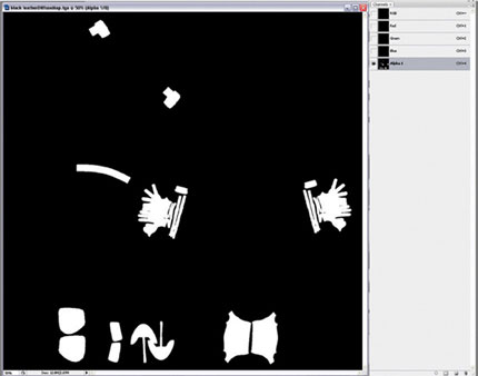
FIG 10.121
Let’s make a new 4096 × 4096-pixel (4k) document to collect all these alpha channels together. Save the new document as Future_Commando_01.psd.
One by one, click on the alpha channel of each of your 14 material renders, copy it (Ctrl + C) and paste the channel (Ctrl + V) into a new channel in the Future_Commando_1.psd file. Once you have named each channel accordingly, you will have a collection of channels as shown in Fig. 10.122.
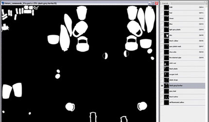
FIG 10.122
Click on the RGB channel at the top of the Channels window and open up the Layers window again. Let’s make a new layer for the NBC suit. Select an off-white color and fill your new layer with this color.
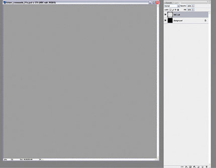
FIG 10.123
Now comes the cool bit: go back to Channels and hold Ctrl as you click on the NBC suit channel to select all the white areas of the channel. Go back to the Layers window and click Create Mask.

FIG 10.124
If you have done this correctly, the mask will hide the areas outside of the NBC suit UVs. The gray color of the NBC suit layer shows only where the mask is white; areas where the mask is black are transparent, so we can see the Background layer underneath.

FIG 10.125
A black-and-white mask icon should have appeared in the NBC suit layer. If you hold Alt when you click this mask, it will be isolated so that you can see the mask clearly in black and white. To deisolate the mask, click on the eyeball icon (Layer visibility) of the NBC suit layer.
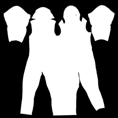
FIG 10.126
Masks and channels are the professional way to edit images in a nondestructive manner; if you want to make changes to something, it often makes more sense to do this with masks. If you don’t like your mask, you can throw it away, keeping the original image intact.
As an advanced Photoshop user, it is imperative that you learn all the ins and outs of layers and masks. Masked layers have two thumbnail images instead of the usual one thumbnail. Click the thumbnail on the right to edit the mask, click the thumbnail on the left to return to editing the color layer. You can Ctrl + click on the mask to select all the areas that are white, which can be incredibly useful for making selections. Shift + click on the layer to toggle its effect on or off.
One by one, you can repeat the “fill new layer” with color and then apply the relevant mask process to each of the 13 different materials that we have a channel for. Try to avoid coloring things black or white, as there aren’t many things that are truly black or truly white. It’s better to settle for off-tones that are more realistic.

FIG 10.127
When all 13 materials have their own color layer and mask, the texture will look something like the previous figure. I don’t like the color of the suit I’ve applied, but it’s too dark, so let’s tweak it with levels. Click on the NBC suit RGB color icon (the one to the left of the black-and-white icon) and press Ctrl + L to bring up the Levels command. Move the little triangles in the levels around to adjust the colors. This is a powerful way to make sweeping changes to your layers or selections.

FIG 10.128
Open up the old AO map that we rendered earlier, go to Image > Image size, and convert it into a 4 k map, then press Ctrl + A to select all, Ctrl + C to copy it into memory, and Ctrl + W to close it. We now have the AO map at 4 k in our clipboard.
Select the top layer in your PSD and press Ctrl + V to paste in the AO map from the clipboard. Name the layer AO. With the AO layer selected, select the Multiply layer mode from the drop-down menu. The Multiply command takes the dark parts of an image and multiplies them with all the colors in the layers below, darkening them. Anything that is white in the Multiply layer is invisible and lighter shades have little effect.
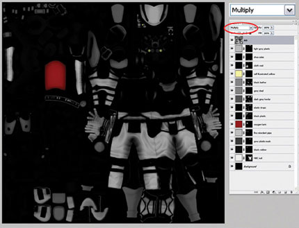
FIG 10.129
To preview the work-in-progress (WIP) in 3ds Max, save out a copy of the PSD as a JPG. Apply a new standard material to your model in 3ds Max and load the WIP jpg into the Diffuse color slot. I like to give the material 100% self-illumination so that I can see clearly every surface on the model—there is plenty of time for gloomy, atmospheric lighting later on. It’s also good to raise the Specular Level to about 50; the specular highlights will help us to see some of the details of the surface.
If your colors are anything like mine, you probably made them all too dark, so go back to Photoshop and sort them out with the levels. Keep tweaking until you get something you are happy with. I’ve put the “Self-illuminated lights” layer above the AO to get the effect that it is lit from within.
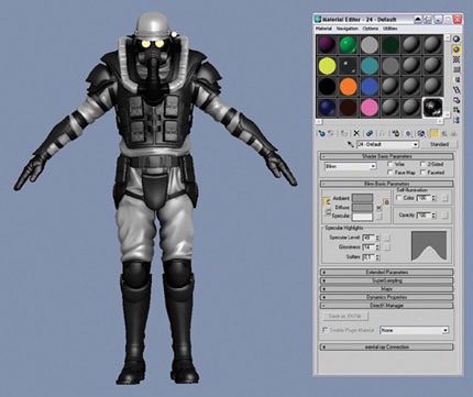
FIG 10.130
Once you are happy with the basic color layers that you just made, it is a good idea to merge them. We still have the channels if we want to make specific selections quickly, and merging all the layers will save us lots of RAM. Select all the layers apart from the AO and the self-illuminated yellow layer (for the eyes and torch), and press Ctrl + E to merge them together. When you have finished, it is a good idea to rename the Background layer: double-click the background layer and type in the name Base Colors.

FIG 10.131
When painting textures by hand, it is much more intuitive to use a 3D paint application—you are not faced with the problem of working out which areas in the UVs correspond to which areas in 3D space. 3D paint applications allow us to paint seamlessly across multiple seams, something that is nearly impossible when painting in 2D in Photoshop. Painting in 3D has another advantage in that if you have any distortion in your UVs (sometimes a little distortion is hard to avoid), the 3D paint application will automatically make predistortion adjustments to your 2D texture to compensate for the distortion. The results will look distorted in Photoshop but perfect in 3D—something that you could never do without the 3D paint application.
Bodypaint 3D is a good standalone 3D paint application, but I recommend the use of ZBrush for your 3D painting. ZBrush’s ZAppLink feature allows it to plug straight into Photoshop for an unrivaled texturing workflow. Why learn the inferior painting tools of another application when we can use the already-familiar and industry-standard Photoshop tools?
Trying to draw with a mouse is a bit like brushing your teeth with a toilet brush—it’s not the ideal solution! Professional texture artists use graphics tablets (digital pens) for any demanding hand-drawn texturing. I recommend the use of the Intuos tablet by Wacom; the pressure sensitivity of pen is excellent.
If you do not have access to a good 3D painting package, you can render a UV template to help you with your painting in 2D in Photoshop.

FIG 10.132
Add an Unwrap UVW modifier to your model, and click Edit to open up the Edit UVWs window > Tools ≥ Render UVW Template.

FIG 10.133
Select 4096 for the width and height and click Render UV Template. A Render Map window should appear with your UV co-ordinates nicely rendered; press the Save button (the disk icon) to save the image to a file. Open up this image in Photoshop, select all (Ctrl + A), copy it (Ctrl + C), and close it (Ctrl + W).

FIG 10.134
Click the top layer in your PSD and paste this image (Ctrl + V) at the top, renaming it “UVs.” Put the layer into Screen mode to ignore the black areas. Now only the white areas should show through to lighten the layers below. You can turn on and off this layer as you require while painting your texture; sometimes, it is really useful for seeing the boundaries of the UVs. I often reduce the opacity of this “UVs” layer to something like 20%.
Our character is looking pretty good now, but he lacks the small, real-world details that will really bring him to life. I almost always paint some kind of dirt map to give a more realistic look to our characters. If you study anything in the world around you, you will notice dirt and small imperfections on the surfaces of objects.
When creating a texture for a character, I try to imagine his or her history and lifestyle. What does the character do on an average day? Where has he or she been? Has your character been relaxing in a pristine palace all his or her life? Or bathing in mud? When treated with subtlety, the incidental effects will really bring your character to life—the eye of the viewer will pick up on these small details that give credibility to your digital creations.
Many companies specialize in producing photo libraries of dirty surfaces, available for royalty-free use in your textures, but they can be quite expensive. A cheaper solution is to take photos of dirty surfaces yourself. Go to your local industrial area, and you will find an area rich with grime. No one appreciates a good dirty surface quite like the 3D artist does!
Figure 10.135 is an example detail from one of my dirt images that I’ve collected, before I cleaned it up and adjusted the levels. I like to photograph smooth white surfaces, as it makes it very easy to get just the dirt without any other surface features that will need to be removed to isolate the dirt. Get as many different types of mud, grease, and dust as you can; the more images you have in your library, the more variation you will be able to include on your characters’ dirt maps.

FIG 10.135
I like to paint on the dirt generously to start with, working fast and rough and not caring too much about any specific details. I mix manipulated dirt images from my photo library with hand-painted dirt using the Paint Brush and Burn tools. Next, I go around the model and clean off the dirt with a white paintbrush in the most exposed areas. If an area looks unrealistic, I will give it a heavy blur, paint in more detail, blur a little more, and then add more detail again. It is this iterative process that helps me to build up a history of past incidents on the surface of the character.
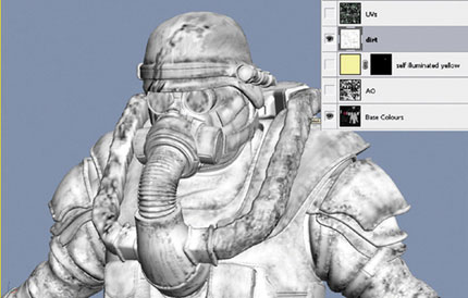
FIG 10.136
Painting your dirt in a 3D application will really make it come alive, as you can see very clearly which parts might not get cleaned as easily and which areas might get cleaned on a more regular basis. Remember that weathering, friction, and collisions will remove the dirt from the most exposed areas, leaving behind the dirt that is protected in the cavities.
If you change the dirt layer to Multiply mode, you will see the dirt on top of the Base Colors and AO layers. If you want a quick and dirty effect, sometimes this is enough, but this technique produces dirt that is only monochrome because of the limitations of Multiply mode. The multiplied dirt layer does not show up very well on any of the darker fabrics, as dark × dark = very, very dark. Dirt usually makes dark objects lighter, so it’s a better idea to use another image to create a muddy color and use our dirt map to mask it.

FIG 10.137
Figure 10.138 is a photo that I took of a muddy area of a field; I’ve used the Rubber Stamp tool to repeat the texture across the surface. This will make a good color for our dirt.

FIG 10.138
To apply our B&W dirt map as a mask to this muddy layer, select the original B&W dirt layer, select it all (Ctrl + A), copy it to the clipboard (Ctrl + C), and then delete the layer. Create a new mask on the color muddy field layer, Alt 1 click the mask to isolate it, and paste (Ctrl + V) in the B&W image from the clipboard. With the mask still selected, invert it (press Ctrl + I) because it is the wrong way around.

FIG 10.139
Here I’ve reduced the opacity of this layer to 40%. Subtlety is the key to getting it right, as we don’t want the guy caked in mud, but his costume must look like it has been used in a real-life combat situation. We can make certain parts more or less muddy by selecting those areas of the mask with our channels and applying a levels adjustment. I’ve deliberately understated the dirt here a little because later we will apply the dirt to the specular map, too, to strengthen the dirt effect. In some areas, I have blurred the muddy colors of the layer to get an ingrained, old dirt look, and I have left other areas of the layer quite sharp to get a new mud feel.
FIG 10.140
In the real world, things get scratched in everyday use—especially on the battlefield! On a new white layer, I’ve painted black scratches; again I’ve used a 3D paint application to help me get the scratches placed well, with the heaviest ones on the most exposed edges. Like the dirt map, I paint super quick and rough to start with and as I do so I try to imagine how the scratches came about. Maybe the scratches on the helmet came from a fall, so they all go in one direction, maybe scratches on the Kevlar forearm pad have built up over time, so they all point in unique directions. Don’t just paint dumb! Think as you paint.
Fabrics don’t often scratch sharply like hard surfaces do, so let’s blur them out a little.

FIG 10.141
Select all the areas where there are soft fabric materials by holding Shift and Ctrl while clicking each of the relevant fabric channels one by one to add them to your selection. Now select Filter > Blur > Gaussian Blur and give these areas a moderate amount of blur. To add more realism, add a mask to the scratch layer and paste in a copy of the AO map, which has the effect of removing the scratches from occluded areas. This newly AO masked scratch layer works well, but we must flatten it so we can use it in another mask—the complexity increases! Add a pure white scratch background layer below the scratch map, select the two layers together, and then merge them (Ctrl + E). Now select and copy the contents of this new merged layer to your clipboard for use in the next step.

FIG 10.142
Many surfaces, such as the gas tanks, have been painted, and they will reveal their underlying materials in areas where they have been scratched. Let’s create this layered effect by duplicating the Base Colors layer (right-click on the layer and choose Duplicate). Name the top layer Base Colors and the layer underneath Under Colors. Paste the contents of your clipboard (the merged scratch map from the last section) into a new mask applied to the Base Colors layer.
Now we can paint in the Under Colors layer to create our underlying material colors. The gas tank should reveal bare metal under the paintwork where it has been scratched, so paint a gray color here. Other metals will typically get lighter where they have been scratched, so just lighten those areas. Some plastic areas might be darker where they have scratched and something has created dirt-filled cavities.
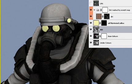
FIG 10.143
If you export the WIP color map to 3ds Max, it should be easier to see how the colors underneath are shaping up. You can use the channel selections to select specific areas and make sweeping changes to many under-colors at the same time. I have also used the Levels command on the scratch mask itself to tone down the effect a little.
For additional realism, let’s remove the dirt from the scratched areas, as it would often be removed by friction as the scratches occurred. I have put the dirt layer in a new folder (group) and masked this new folder with a copy of the scratch mask from the Base Colors layer. Nesting masked folders inside folders is incredibly powerful, but can quickly get confusing! Our scratch map will really come alive later, when we can use the specular map to make the scratched areas shinier.
Painting the High-Frequency Detail Layers
Next let’s paint the high-frequency (HF) details—the things that crop up again and again across the surface (e.g., skin pores, the pattern of the sole of the shoe, the ribbed pattern on the belt, and so on). Details on this small of a scale are much easier to create using texturing rather than modeling.
I like to create the HF details as black-and-white maps; this means that later we can easily pop out these details in the normal map.
The first step is to gather high-resolution images of each fabric type we will use. Many of the surface types, like the rubber and the plastic, are smooth surfaces that don’t require HF detail maps, but we will need images to make the microbumps of the leather, elastic, cloth, NBC suit, and the fire-resistant material on the piping. Like with the dirt, I keep a library of photos of different fabrics; you can buy disks full of fabric textures from the Internet, but I sometimes find it quicker and cheaper to source my own from around the house and quickly take photos/scans of them. Like most reference material you use in your textures, it is much better if it is shot in diffused lighting conditions with no harsh lighting, shadows, or hard contrasts.
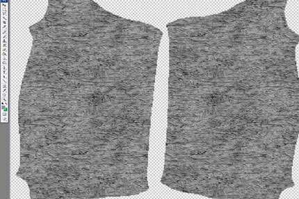
FIG 10.144
Adjust the maps so that they look similar to how the AO map would look if we had actually modeled every HF microcavity in to the surface of the object. Black represents the lowest areas, and white represents the highest points that are more exposed to the light. Figure 10.146 shows my HF detail layer, which describes the creased, wrinkly texture of the leather.

FIG 10.145
Each type of surface should tile to completely fill its own HF detail layer; to keep things tidy, put all the layers in a folder called “HF details.” We can use the channels we saved earlier to quickly create a mask for each layer, Ctrl + click the relevant channel to select the areas it masks, and then back in the Layers palette, you can click the “Create mask” icon to quickly mask the active layer with your selection.
Set each of the HF detail layers to multiply, so they have a similar effect to how our AO layer works, darkening the occluded areas.
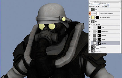
FIG 10.146
Let’s add another layer of realism to our creation using Normal and Specular maps. Normal maps are used to fool the eye into thinking that there is much more detail than there actually is modeled into the character. They work in a similar way to bump maps, by cheating in the details. Specular maps control how shiny the surface is in different areas: white pixels make the metal look shiny and the black pixels make the dirt look totally matte.
We can see the effects of the normal and specular maps in real time in the viewport if we use a special DirectX shader written by Ben Cloward.
If you visit www.bencloward.com/resources_shaders.shtml, you can see that Ben has created a wealth of different shaders that you can use in the 3ds Max viewport to simulate various surface effects. Read all about these shaders here: www.bencloward.com/shaders_NormalMapSpecular3lights.shtml. He has kindly allowed us to include the “Normal Map Specular Shader—3 Lights” shader on the book DVD. Find Ben’s shaders on the DVD ROM here: Chapter103ds Max Files for chapters10_highres_mesh_textureddirectx_shaders and copy them to somewhere easily accessible on your hard drive. Before we set up the shader, we need to use Photoshop to make some quick, temporary normal and specular maps to plug into the shader.
To make a temporary normal map, use the Paint Bucket tool to fill a new 4 k image with RGB color 127,127,255. This purple/blue tone has the effect of perfect flatness in normal maps; it’s the normal map’s equivalent of black or zero—it has no effect. Save this as something like Future_Commando_Normals.jpg.

FIG 10.147
To create a temporary specular map, let’s use the Paint Bucket tool to fill a new 4 k image with RGB color: 127,127,127. This is a good medium gray color for a moderate level of shininess. Save the image as something like Future_ Commando_Specular.jpg.

FIG 10.148
Now we have a color and a normal and a specular map. Let’s set up the DirectX shader. In 3ds Max, apply a new material to the character model, and then click on the Standard button in the Material Editor to select a DirectX type of material.

FIG 10.149
Click the top-left box in the DirectX Shader Panel, the one with the long path name in it. This box loads a specific DirectX (.FX) shader onto your material. Browse to the folder to which you copied Ben’s shaders and select the one named HLSLnormal_map_specular_3lights_world.fx.

FIG 10.150
Now Ben’s shader is applied to your character. Most likely, the model will turn black, as the maps are not loaded in yet. Click on the slots next to Diffuse Texture, Specular Texture, and Normal Map, and load in the relevant maps.
Once you have loaded the three maps into the relevant slots, you should see the shader displaying correctly. The normal and specular maps are just filled with temporary, basic colors, so we are not really getting the benefit from this shader yet. The default settings use the 3ds Max Default Light, but it is better if you make three omni lights that surround the character and load each one into the Light Position slots, as explained below.

FIG 10.151
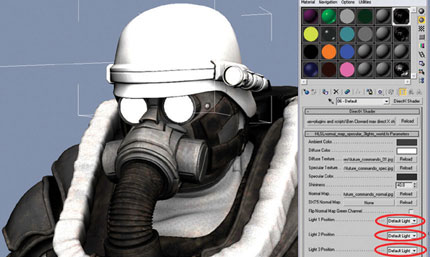
FIG 10.152
Using Create > Lights > Standard Lights > Omni, make one Key light that has an intensity of around 1 and is positioned at the front of the character, but a little to one side. At the other side, make a Fill light with an intensity of about 0.5, and at the back a Rim light with an intensity of around 0.5, too.
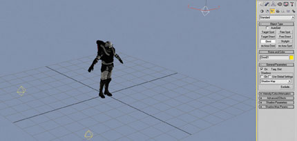
FIG 10.153
You can tweak the light settings to your own preferences; it’s all just to help you see what is going on with the normal mapping later on. You can even animate the intensity and positions of the lights so that you can play the time line to see the character in different lighting conditions.
Normal Mapping the High-Frequency Details
We can really give the HF details much more punch if we pop them out using a normal map. As it is just a texture-mapping effect, this illusion breaks down when viewed up close, especially when seen at angles perpendicular to the viewing angle where it is obvious that the details are not truly 3D. Normal mapping does not work well as a replacement for modeling the larger geometry, as it does not affect the silhouette of the shape in the way that modeling does.

FIG 10.154
To follow my style of normal mapping, you will need to install the NVIDIA Normal Map Filter for Photoshop, which is available for free download from here: http://developer.nvidia.com/object/photoshop_dds_plugins.html.
One by one, feed the contents of each of the HF detail layers to the Normal Map Filter. The Normal Map Filter does not work on PSDs with more than one layer, so one at a time, copy the contents of each HF detail layer and paste each one into a new document, being sure to flatten each image down to just one background layer.

FIG 10.155
With one of your temporary, one-layer HF detail documents selected, choose Filter > NVIDIA Tools > NormalMapFilter to bring up the options for our normal map.
Although there are lots of options here, all you really need to do is type different numbers into the Scale Box. The Scale setting describes how powerful the effect of the bumpiness of the surface is. I find that 6 works well for me most of the time. You can also press the 3D Preview button if you want to see how your normal map will look in real-time 3D. Press OK to create your normal map.
Create a new PSD file called Future_Commando_01.psd and one by one, paste in the normal maps that you have generated for each HF detail layer.
To blend all these maps together, copy over the masks from the original HF detail layers in the color PSD (Future_Commando_01.psd). Your Future_ Commando_Normals_psd should look something like the Fig. 10.157. I’ve zoomed in to 300% to show the details. I like to add a little note for myself on the name of each layer: L3 means that I generated the map with a scale of 3, L6 a scale of 6, and so on. These notes will help us if we decide to tweak the strength of each one later on.

FIG 10.156

FIG 10.157
In the normal map PSD document, select “Save As” and overwrite the temporary Future_Commando_Normals.jpg map that we made earlier. If you go back to 3ds Max now, the new map should have automatically loaded into the material and the normal map should be displaying nicely now. You should export your normal map to 3ds Max frequently as you work because reviewing the normal map applied to the character in 3ds Max is much easier than staring at a bunch of blue colors in Photoshop.

FIG 10.158
In the previous figure, I’ve decided that the NBC suit material is too bumpy, so I’ve toned that down by changing the opacity of the NBC L3 layer to 6%. I’ve also gone back to the color PSD and made his vest a little bit lighter.
Before we finish the texturing with the specular map, there are a few finishing touches to add to the color and normal maps. As these details are all very flat, we won’t be generating normal maps from them, so they can all be painted on the Base Colors layer.
The Danger Label on the Gas Tank
I drew the shapes for the Danger label using the Rectangle and Polygon Selection tools, using the Brush tool to fill the selections with color and the Edit > Stroke command to outline them where needed. I used the Text tool to create the typography, and then merged everything down onto the Base Colors layer, making sure to preserve the (scratch) mask. Be sure to make the yellow tones a slightly desaturated yellow; in the real world, most things are not completely saturated with color, but usually faded from weathering.
At the moment, your metal areas are probably looking a little flat and boring; better that we give them an interesting texture. To build up the texture, use Filter > Add Noise, and then Filter > Blur > Gaussian Blur a number of times, entering smaller numbers into the Size parameter on each iteration.
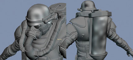
FIG 10.159
If we were working on a character for a feature film that would be viewed close-up, I would probably model the inner workings of the glowing eye and torch, and add some cool render effects. However, as this texture will eventually need to be baked down onto a 1-k game mesh, it is probably too much work on this project to get bogged down in this level of detail. In production, you have to draw a line somewhere on the level of detail or you will make too much work for yourself and miss your deadlines.
I drew the glowing torch and eye lenses by hand using the Brush tool, and then overlaid a grid image in Color Burn mode. When I was happy with these layers, I merged them together onto the self-illuminated yellow layer to save a little RAM.

FIG 10.160
Many surfaces are not as perfectly smooth and flat as you might assume. Accidents, daily use, weathering, factory defects, and warping caused by sun exposure all lead to small imperfections on surfaces.
To create this effect of less-than-perfect surfaces, let’s paint another black-and-white map that we can feed into the NVIDIA Normal Map Filter. Starting with a mid-gray background, you can use the Burn tool to darken areas that you would like to push down in the normal map. If you hold Alt when using the Burn tool, it will dodge instead, lightening the areas, and thus raising them in the normal map. You can paint these micro bump dings onto the helmet, gas tank, shoes, and anywhere else where you’d like to make the surface less regular. Generate a normal map from this black-and-white image using the NVIDIA filter and place it in the top layer in the normals.psd. If you put this microbumps layer into Overlay mode, it will blend over the top of the existing normal map layers.
The High-Resolution Specular Textures
Creating the specular map is fairly straightforward; for the most part, we will use already-existing elements from the color PSD. We will create a number of new “Specular” layers that we can turn on to convert our color PSD texture into a specular map.
The adjustment layers (icon shown in Fig. 10.161), which are found at the bottom of the Layers window, are great for making nondestructive changes. Adjustment layers can be turned on and off and masked, and if you don’t like them, you can just delete them to return to how things were before.

FIG 10.161
Select the top layer in your PSD (probably the UVs layer), click the “Create new fill or adjustment layer” icon, and Select Hue/Saturation. Drag the Saturation control down to −100 to totally desaturate everything underneath this adjustment layer and press the OK button. Right-click on the new adjustment layers mask and choose “Delete layer mask”; this step will save a little of our precious RAM, as we don’t need the mask. Now give the layer a meaningful name, like “Specular Desaturator.”
Create a new layer above the Base Colors layer called “Specular Colors.” One at a time, select each channel that we saved earlier and fill that selection with a color. Fill Specular Colors with black for nonreflective (specular is just a cheated reflection, really) things like cloth. Fill Specular Colors with medium gray for things that have a moderate amount of shininess, like the NBC suit and plastics, and fill it with white for very shiny things like metal. This layer should completely block out any layers below it.

FIG 10.162
My aim when creating the specular map is to break up the highlights; the specular map is where I concentrate the majority of the grime and dirt in the textures. As I’ve mentioned earlier, if you look at even the newest objects around you, you will notice that the reflections on their surfaces are broken up by imperfections, fingerprints, dirt, and scratches.
Let’s improve our specular texture by making the dirty areas less shiny and the scratched areas shinier. Copy the dirt and scratch masks that we made earlier and paste duplicates of them at the top of the Layers window next to the Specular Desaturator layer. Name them “Specular–dirt is darker” and “Specular–scratches are lighter,” respectively. Now if you put the “Specular–dirt is darker” layer into Multiply mode, it will make all the dirty areas not shiny; if you put the “Specular–scratches are lighter” layer into Screen mode, it will make all the scratched areas shinier. (You might need to invert it, too.) I also adjusted the levels of these maps to amplify their effects.
Right-click on all the new specular layers one at a time, selecting Layer Properties and applying a gray color. It will now be easy to identify which layers are for the specular map, an ability that will reduce user errors when we toggle our PSD between color and specular modes. If you use Save As and save this image over the temporary Future_Commando_Specular.jpg texture, you can check the new specular map in 3ds Max.

FIG 10.163
In the DirectX shader, make sure that the Specular Color is set to white, so you can accurately tweak your specular map. It’s now just a matter of tweaking the three textures to your taste. When you are finished, you can re-export the textures in TIF format to increase the quality.
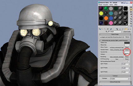
FIG 10.164
After a discussion with the team, it was decided that an over-the-top, multifunction gun would best suit the battlefield needs of our soldier. As we didn’t have a concept image for the gun, I blended together elements from several existing weapons into one design, mixing together a flamethrower 3ds Max Modeling for Games and a chain-gun. It had to be big, as we didn’t want our soldier to feel inadequate on the battlefield! The weapon required additional fuel tanks to be fitted to the existing gas tank to supply the flamethrower with fuel. As these are detachable items, the gas tanks and the weapon both have their own separate texture sheets.
For our game mesh, we have been allocated a polygon budget of 12,000 triangles. This is a reasonable amount for a prominent game character for a first-person shooter on the Xbox 360 or the Playstation 3. Background characters that don’t receive all the limelight might get only 2000–5000 triangles, but lead characters that are designed for talking in close-up shots might get 15,000 or more polys.

FIG 10.165
Earlier, during the modeling of our high-resolution mesh, we wisely saved a copy of our work-in-progress proxy mesh when it was around 6000–7000 triangles (for half the mesh). This basic, approximate form will make an excellent starting point for our game mesh. If we load up this old .OBJ mesh (File > Import), it should fit perfectly over the top of our high-resolution character. Add the Symmetry modifier and give this proxy mesh a green material with opacity of 50% so that we can clearly see the high-resolution mesh underneath it.
Using all the familiar Edit Poly tools, we now need to optimize this mesh for use in videogames, aiming to get the half game mesh to around 6000 triangles. The core idea when creating real-time assets such as this is that each triangle/polygon is precious. If we can reduce polygons in one area without any detrimental effect, we can spend these elsewhere in the model to improve the overall appearance. Ideally, we can keep a clean, quad-based topology, but a few triangles here and there are fine.
The way I construct my game meshes owes much to my previous experience with using normal maps. Normal maps are great at representing the many small details, but they are very poor when used to fake the larger features, which should always be modeled in. Sometimes, we can delete many polygons from a relatively flat area and let the normal map do the work instead, without the surface looking much different.
I spend lots of polygons on creating a detailed silhouette because only geometry can give us a detailed and interesting profile. Sometimes I change the material so that it has 100% self-illumination, which makes it easy to focus on just the silhouette. View your game-mesh model from every angle and see whether its silhouette looks correct. If you press F4 to toggle edged faces, you can see whether there are areas with lots of polygons that are contributing very little to the silhouette, and then track them down and delete them.
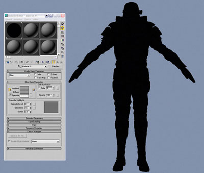
FIG 10.166
Typically, an in-game character will be rigged and animated through a wide range of poses, so we must take care that the geometry we build around areas that bend (knees, elbows, shoulder, wrist, and so on) has enough detail to support a full range of movement. The best way to get a feeling for this is to rig your own meshes and test-animate the rigs so you can experience firsthand exactly where geometry is needed and where you can scrimp on it.

FIG 10.167

FIG 10.168
One edge loop on a joint is often not enough once you start animating the character.
When in doubt, a good rule of thumb is to have at least three edge loops around each joint to allow for correct deformation during animation.
Modeling for games sometimes involves using some low-down dirty tricks! Knowing when you can pull these off and when to do things the proper way is an art form in itself. Some people might tell you to make sure that all areas of your mesh are welded together. Granted, this approach works better in some situations, but we can save lots of polys in some areas if we disregard this advice. Andy Gahan showed me the following trick when I first started to work on PS2 games, but it’s as relevant as ever for the current generation of games.

FIG 10.169
As an example, take a typical cylindrical object with some beveled detail like the one in the following figure. The highlighted polygons here contain 24 triangles; let’s delete them.
Select two opposite edges and use Edit Polys Bridge command to join them together; repeat the Bridge operation for each set of opposite edges.

FIG 10.170
Now we have two overlapping shapes rather than one whole mesh. The new polygons we have added contain only 10 triangles, a savings of almost 60%!
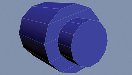
FIG 10.171
If we use this trick on the ends of each cylinder on the gas tank valves, we can make substantial savings. Here I saved 30 triangles by deleting the old welded ploys and replacing them with new bridged edges. There is a gas tank valve on each side of the character, so this is a total savings of 60 triangles. Look for other areas to perform this trick and save additional polys that we can use to improve the detail in complex areas, such as the creases and folds of the NBC suit.

FIG 10.172
You should avoid the use of this trick in certain deformable areas, as the open edges may get exposed during animation. The only way to get a good feeling for how far you can push this is to get firsthand experience with rigging and animating game meshes.
When finishing off the model, I like to turn on the Edged Faces in the viewport and squint my eyes at it so I get just a hazy general impression of the mesh topology. This makes it easier to see areas where the polygons are denser and areas that are relatively sparse. Unless there is a special reason (animation, silhouette, or mapping), all the meshes should have similar levels of detail. Sometimes I rob from the rich to give to the poor, taking polygons away from areas that don’t need them.
Many games give a bias to the head when it comes to detail. The viewer’s eye naturally focuses here, so it is worth spending a bit more of your budget here. Some games feature the characters up close in animated dialog shots, so they are built with lots of detail in the face, designed to smoothly morph between different emotions and mouth shapes.
Like the high-resolution mesh, it’s good to UV the half game mesh before you mirror it. You should try to minimize the number of UV shells. The fewer shells, the fewer seams, so join them together whenever possible.
When you have the Unwrap UVW modifier applied to your object, the seams show up as bright green lines. I try to hide the UV seams in areas that won’t be seen easily, like the inside of the legs or the inside of the arms. Better still, I line up the seams with areas where there are already fabric seams in the high-resolution mesh (the areas where the garments are stitched together or the intersection between two different surfaces).

FIG 10.173
It’s worth noting that sometimes developers give a bias to the UVs of the head and the eyes; that is, they make them larger to fit in more detail. But as our character is intended for a fast-paced arcade game with few dialog scenes, this won’t be necessary.
Once you’re happy with the UV seams, add a Symmetry modifier and collapse the stack into an Editable Poly to create the full mesh.
Now that we have the whole mesh, we can create the creases and folds that are unique to the left-hand side of the NBC suit. It is also possible to save some more polys by deleting any edges on the line of symmetry that aren’t contributing to the character’s form. Once you have finished modeling, select the new half of the mesh and horizontally flip the UVs. In UVlayout, it is now straightforward to complete the UVs by welding all the seams that run up the center line and reflattening all the pieces. In the previous figure, I have cut off the codpiece as a separate UV shell to avoid having a seam that runs down the line of symmetry. As always, remember to pack your UV shells as tightly as possible.

FIG 10.174
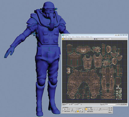
FIG 10.175
Baking Down the High-Resolution Details
To produce the highest quality meshes for Playstation 3 and Xbox 360 games, the colors and details of the high-resolution mesh are often baked down onto the comparatively low-polygon game mesh. The game mesh’s normal map does a great job of faking the high-resolution details, giving us almost the same effect for a fraction of the system resources of the original multimillion-polygon mesh.
The high-resolution and in-game meshes should now sit perfectly over the top of each other like the following figure. Be sure that the high-resolution meshes have standard 3ds Max materials, with the color, specular, and normal maps applied to the relevant map slots. Make sure that no DirectX materials are applied to the high-resolution objects, as they cannot be baked down onto the game mesh.
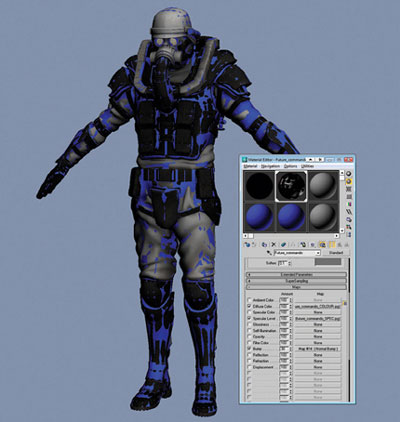
FIG 10.176
We could go through and bake our maps one by one, but it is easier to bake all three maps (color, specular, and normal) at the same time. Select the game mesh and select Rendering > Render To Texture. In the General Settings tab at the top of the Render To Texture settings, choose an output path for the textures.

FIG 10.177
Be sure to check the Enabled box in the Projection Mapping section and click the Pick button to bring up the Add Targets menu.
In the Add Targets pop-up box, select all of the objects that make up the high-resolution mesh; in my case, this is the main body of the future commando and the gas tanks. Click Add and a Projection relationship will be set up between the game mesh and the high-resolution objects.
To set up the normal map output, click Add in the Output section and choose a NormalsMap Texture element. Choose Bump for the Target Map Slot to ensure that Render To Texture will plug our new normal map into the bump slot of the new material that it will apply to our character. Click the 1024 × 1024 button to choose a 1 k map size. Be sure that “Output into Normal Bump” is checked, so that the normal map gets plugged into bump slot through a Normal Bump node.

FIG 10.178
Now we have the NormalMap output all set up, let’s configure the specular map bake. Click Add and choose a SpecularMap Texture element. Choose Specular Level for the target map slot. Click the 1024 × 1024 button to choose a 1-k map size.
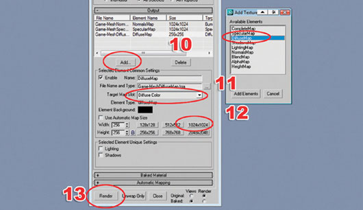
FIG 10.179
Finally, let’s set up the diffuse/color map bake. Click Add and choose a DiffuseMap Texture element. Choose Diffuse Color for the target map slot. Click the 1024 × 1024 button to choose a 1-k map size. Click Render to render out all three maps at the same time and apply them to a new material.
Isolate the game mesh or hide the high-resolution mesh to view the work so far. In Photoshop, browse to the location where you saved these textures, and open them up to take a look at them.

FIG 10.180
Back in 3ds Max, you will notice that a blue cage has appeared around the game mesh and that a Projection modifier has been added to its stack. The blue Projection cage is a visual tool to help you control how the information is baked down from the high-resolution target mesh onto the low-resolution one. During a render, rays are fired out from each point on the game mesh until they get to the cage, from where they take the information from the nearest high-resolution surface.
When baking from high- to low-resolution, there are often some problems. Cavities and other complex areas with overlapping details cause problems for the renderer because when there are many high-resolution surfaces close to each other, the renderer doesn’t know which one to take its information from. The Projection cage is designed to solve this problem, as each vertex in the cage can be tweaked by hand, but because we have more than 6000 vertices in this mesh, the prospect is daunting!

FIG 10.181
Luckily, there are controls in the Projection modifier that can move each vertex on the cage all together at the same time. If you type various values into the Auto-Wrap parameter and hit the Update button, you will see the cage recalculate at different distances from the game mesh.
My favorite and fastest way to get perfect game-mesh maps is to bake each of the maps a number of times, each with a differently sized cage. Often I will bake a small, medium, and large version of each map, which I blend together in Photoshop using masks.
To fix the color map, I rendered first with a small cage and then in the areas with missing information, I painted in (using a mask) another version of the map I had rendered with a larger cage. To quickly finish it, I used the Brush tool, Rubber Stamp tool, and Healing Brush tool to make a few quick and dirty fixes on the layer that was corrected by hand. I fixed the problems with the specular map using exactly the same techniques.
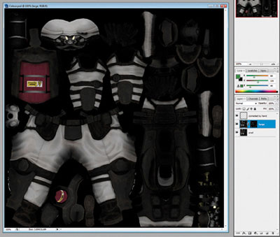
FIG 10.182
To fix the normal map, I used the same process as I did for the color map, with a couple of additional techniques. I corrected some of the areas that had rendered incorrectly by painting the blue/magenta color R127, G128, B255 on the hand-corrected layer.

FIG 10.183
The low-frequency normal maps that we obtained from the baking process do not include all the high-frequency details that are in the normal map of the high-resolution version of the character. To add these details to our mesh, apply the normal map of the high-resolution character to its diffuse color channel instead of its usual bump channel assignment. Then when you bake the maps again, the high-resolution normal map has been baked into the DiffuseMap texture. Copy and paste this map into our game-mesh normal PSD and put it in Overlay mode to blend it over the top of the other normal map layers.

FIG 10.184
It is very useful to apply the DirectX shader that we used earlier so that we can preview the effects of the specular, normal, and diffuse maps all working together in real time. If you keep a sharp eye out, you can make the game mesh incredibly similar to its original high-resolution counterpart.
So we’ve finished the character now, and although he looks pretty darn good in the DirectX shader in the viewport, we can make him look nicer still if we render him using the Scanline renderer. True high-end rendering is beyond the scope of this chapter, so we will use specular highlights to approximate blurry reflections and AO maps to approximate the diffuse scattering of light.
I will show you how to render the high-resolution asset, but I recommend that you render the game mesh, too; potential employers are keen to see what you can do with a restricted polygon count. Dramatic, shadowy lighting looks cool but doesn’t give a detailed view of your model; perfectly flat, even lighting looks unrealistic and doesn’t show off the contours of your model. Here we will create a lighting scheme somewhere between these two extremes. To start, delete any old lights from the scene and apply a blank, gray material to the character.
Although it will not be the focus of the renders, a simple and well-lit scene can help show off our character and put him in a real-life context. I used the Primitive Plane object and a couple of bend modifiers to make a primitive photography studio wall like you see below. Gradually curved wall-to-floor backdrops like this allow photographers to get the most minimal backgrounds possible, with no hard corners or other visual distractions. To add a little real-world believability to the studio floor, I’ve added a color texture with some marks on the floor where people have been standing with their dirty shoes on.
Be sure that the Studio Wall object and the soles of the character’s shoes are exactly touching, without penetrating or crossing each other. A floating character or one that sinks through the floor will destroy the illusion of realism.

FIG 10.185
Using the AO baking, like we rendered previously for the character, we can calculate the lighting for the studio wall. Render the AO map and apply the texture to the diffuse slot of the Studio Wall object.
The AO shadow texture on the floor will add a subtle “this character is really standing here” ambient shadow effect. If you take this AO map into Photoshop and multiply it over the top of the dirt-textured floor, you will mix the two for a nice-looking background.

FIG 10.186
Create a camera a good distance away from our character and point it at him. Now zoom in until he fills the screen in the Camera viewport. Remember, the further away the camera, the less perspective distortion. We will be doing square renders, so in the Render Scene options, set a width and height of 512 pixels for our test renders. Right-click on the camera name in the viewport and turn on Show Safe Frame in the options so that you can see the proportions of the camera in the viewport.
When creating lights, it is essential to add them one at a time so that you can see the effect each one has on the scene. With lighting, more is less, so make sure that each light you create has a purpose.
To create our key light, go to the Create > Lights panel and choose a Target Spot light; drag to create the light and point it directly at the character—the default intensity of 1 is usually okay. Normally, key lights are in front of the subject, often to one side to help show off the form of the shape. Lighting that is too close to the camera makes your objects look flat, so it’s better to have this main light off to the right-hand side.

FIG 10.187

FIG 10.188
Be sure to check the Shadows On box to turn on the shadows. If you were to render now, you would get the hard-edged shadow look so common in CGI (Computer Generated Images). Interior light is usually quite soft, as the light bounces around quite a lot compared with outdoor scenes. Photographers often use silk or other translucent materials in front of their harsh studio lights in order to spread out the light and soften the shadows. We can simulate this effect by changing the size of the Shadow map to 128 pixels (a very rough setting) and the Sample Range to 12 (to smooth out the effect).
FIG 10.189
In the Spotlight parameters, you might also want to increase the Hotspot and Falloff of the lamp. Do a test render and you should get something like the previous image.
Photographers often use fill lights to fill in the shadowy areas of their subjects; in CG, we use fill lights for similar purposes and also use them to simulate the effect of bounced light from the environment. Add lots of Omni lights around the character, each with no shadows and a tiny Multiplier value like 0.03. You might want to give the lights to the left a slightly blue tint to simulate the ambient light of the sky coming in from a large window. It is also a good idea to give the other Omni lights and the main key light a slightly orange tint to simulate the hue of a light bulb.

FIG 10.190
Rim lighting is used in photography to really pop subjects out from their background. Make a copy of the key light and move it to the other side of the character. This process should wrap up an interesting lighting scheme, which shows off the complex modeling we have done.
An object’s reflective qualities are dictated by how rough or smooth the object is on a microscale.
Diffuse reflection occurs when light hits a rough surface and is scattered in many directions. Surfaces with 100% diffuse reflection look the same no matter which angle you view them from. A good example of a surface with pretty much 100% diffuse reflection would be a dirty, old cardboard box.

FIG 10.191
Specular reflection occurs when light hits a smooth object and bounces off at a perfect right angle. Specular reflection is easy to identify because it changes depending on the viewing angle. A mirror is a good example of an almost perfectly 100% specular reflective surface.

FIG 10.192
Different ratios of mixed diffuse and specular reflection occur on most surfaces. These surfaces are not flat enough to show perfect reflections like a mirror, but they are smooth enough to ensure that most of the light bounces off in a consistent direction to create blurred reflections. A good example of this would be most metals; they are very shiny, but the details of the reflections are blurred.

FIG 10.193
To simulate these different types of surface in 3ds Max, we will split up the mesh into a number of smaller meshes, each with its own material:
• Blurred Reflections should be applied to all the objects with hard, shiny surfaces like metals and plastics. This material uses the standard Specular effect to fake the look of blurred reflections; true blurred reflections are very computationally expensive and available only on the more advanced renderers, but this cheat will suffice for us here.

FIG 10.194
The micro roughness as I talked about earlier can be achieved using the Glossiness control; a value of 37 will give tight, smooth highlights.
• Blurred Reflections Rough should be exactly as Blurred Reflections, but with a tweaked Glossiness value of 11. This material should be applied to all the fabrics with fairly rough surfaces, like most of the fairly matte clothes and straps.

FIG 10.195
• Blurred Reflections Mid represents the medium-roughness areas and should have a Glossiness of something like 21. Apply this material to the NBC suit and leather areas.

FIG 10.196
• Self Illumination should be applied just to the eyes and lens of the torch; it will be just a regular texture, but with the Self-Illumination setting at 100%.

FIG 10.197
Now all that remains is to plug the relevant color and specular maps into the Diffuse Color and Specular Level slots of these four materials. To apply the Normal Map click on the Bump Slot and choose Normal Bump, and then click on the Normal slot to apply your bump map.
Back in the Maps section of your material, take care to change the Bump value from its default of 30 up to the full strength of 100.

FIG 10.198
For the final renders, increase the resolution to 1024 × 1024 or more pixels. In the previous figure, I have linked all the objects of the character to a dummy so that I can easily rotate the character (by rotating the parent dummy) for different renders.
As we have modeled some pretty awesome detail into our soldier, you might also want to do some close-up renders to showcase our attention to detail.
The renders I have produced here have a kind of stylized, cartoony feel to them because of the manual cheating we have done in the lighting. Quite often in videogames this is a good thing, as many projects require a stylized effect. Setting up the lighting manually like this gives you ultimate control.
We could have gone further with the rendering to achieve a higher level of realism. To improve the quality of the light, we would have to discard the AO layers from our texture maps and use a true “global illumination” renderer such as Brazil, Mental Ray, or V-Ray. These high-end renderers can accurately render real-world lighting effects such as color bleeding, caustics, area lights (3ds Max’s standard lights are infinitely small), and blurry reflections.

FIG 10.199

FIG 10.200
As a 3D artist, you must constantly improve your work to keep up with the rapid pace of change. And at the end of a project (after a good rest, of course!), it’s a good habit to perform a little postmortem on your work. What could you have done to make it better? How could you have made the process faster? How does your work compare to that of your peers? If you learn from your experiences, you will build your next character faster, and it will be of higher quality, too.