
3
Bootstrapping and Security
When light switches were physically inserted into the wiring that delivered electrical power to a specific light, each of them had a very physical relationship with the circuit it was controlling. There never was a need to configure, or commission a physical light switch –commissioning. Obviously, this no longer works for wireless light switches. A 6LoWPAN light switch that has lost its memory when it receives a new battery has to (not necessarily in this order):
- find the LoWPAN it is going to be part of;
- establish networking parameters such as the IP address prefix and its own IPv6 address;
- establish security associations with the relevant entities in the network;
- build paths out of the node to the relevant entities, maintain those paths and possibly start forwarding for other nodes in the network;
- establish application layer parameterssuch as who is interested in when the light switch is operated;
- establish security associations with the relevant entities at the application layer;
- start the application layer protocol, e.g. by making known the current position of the switch.
Some of this establishment of state has to be repeated dynamically over small timescales, such as the selection of the router to be used and the routing paths used for any forwarding. The selection of routing paths is done using a routing protocol, see 4.2, which may also assist nodes in the selection of routers. Other parameters are less dynamic. Their setup can be structured into two phases:
Commissioning. Some of the establishment of state will require human intervention; e.g., somebody has to decide and enter into some part of the system which lights will be controlled by the light switch. This is also the time when security relationships are initialized that will enable protecting the network and its devices and applications against attackers and accidents.
Bootstrapping. After commissioning, the node is set up to operate without further human intervention. However, there may still be state that needs to be acquired, both when a device initializes (power-up with fresh batteries) or when it enters a LoWPAN (see also Section 4.1).
Note that there are a range of activities involved in bringing a node into operation, and it is not always clear whether a specific activity is commissioning, bootstrapping, or part of a dynamic protocol such as routing. The human intervention that distinguishes commissioning from bootstrapping may be mediated through a management system, making the commissioning process itself fully automatic from the point of view of the device. Little has been standardized that could be used to enable interoperable commissioning of this kind, so we will discuss it in general terms in Section 3.1. However, there is one protocol in IPv6 that is clearly related to bootstrapping: Neighbor Discovery. This protocol has been optimized for 6LoWPAN, see Section 3.2. Finally, commissioning and bootstrapping have a strong relationship with security, which is therefore discussed in Section 3.3.
Most 6LoWPAN devices will be manufactured as generic devices and will leave the factory without any information that would enable them to function in a specific setting. The process of providing them with this information can be (part of what is) called installation, configuration or provisioning. As each of these terms has a specific connotation, we will use commissioning as an umbrella term for all these activities; we will use installation for the process that makes a device available in its intended usage setting, and reserve the term configuration for (establishing) the set of information that is instilled in a device in the process of commissioning.
In order to enable a device to bootstrap in a LoWPAN, it needs to know some basic parameters. As many readers will be familiar with the setup of IEEE 802.11 devices, we will start with an analogy to wireless LANs (WLANs). A WLAN station that is to be commissioned to work in an IEEE 802.11 network usually needs to know two items of information:
- How to find the network, or which network is to be joined. Mostly, this requires the knowledge of an SSID (service set identifier); sometimes, further configuration is required for selecting the variant of IEEE 802.11 in use and the frequency band (WLAN stations are usually frequency-agile, i.e., can detect which of the specific channels is being used in the frequency band(s) they support).
- Security information. The station needs to know which method is used for protecting the network and the keying materials needed, e.g., a pre-sharedkey for “personalWPA” (wireless protected access) or username/password for certain forms of “enterprise WPA”.
The information needed for setting up a WLAN base station (access point) also includes both an SSID and the security configuration to be used for the network; however, additional information may be required such as the frequency/channel to be used and some information about the kind of backhaul such as Ethernet or a wireless distribution system (WDS).
Similarly, a LoWPAN device needs to have some way of identifying the network as well as some security information. Often, a LoWPAN device will not be configured to be frequencyagile, i.e. it will not search the channels for available networks but be statically configured to a specific channel (see Appendix B.1 for the channels defined in IEEE 802.15.4). There is no such thing as an SSID in IEEE 802.15.4; instead, a node can assume that it has found “its” network when the security parameters and keying materials match, i.e., the integrity checks of incoming packets do not fail. In addition to enabling the device to join the desired LoWPAN, parameters may need to be set for applications to find the appropriate peers.
There is a trade-off between the efficiency of setting up state once and for all at commissioning time and the flexibility enabled by dynamically discovering this state, at bootstrapping time or even later. As an example, providing the network prefix at commissioning time would reduce the need for Neighbor Discovery Router Advertisements (RAs). But prefixes can and will change; should each such event require recommissioning?As a compromise, the device might cache information it acquired through bootstrapping.
One way to perform commissioning is to set up the devices during production at the factory (if manufacturing is by special order or as part of a just-in-time process). This means that the installer just has to pick up the right device and place it in the right setting, e.g. an electric meter in the right household. Using a just-in-time production pipeline, this can be a very efficient process. The disadvantage is that any disturbance of this process, such as a defective device or damage incurred during installation requires an exception process (e.g., obtaining an installer device and falling back to time-consuming manual configuration) or possibly even waiting for new production.
An alternative is to deliver the devices in an unconfigured state and do the target-specificcommissioning during delivery, or during installation at the target. This often involves the use of a special installer device that communicates with the device to configure it using outof-band means that may include barcode labels, infrared or near-field communication, USB plugs, or any other kind of wired plug-in interface.
Finally, the device could be set up using in-band communication, i.e. using 6LoWPAN communication. It is hard to do commissioning this way that is both fully automatic and secure, as a completely generic device cannot be distinguished from another completely generic device, so how does an installer device know that it is indeed talking to the right device? There is one item of information that must have been set up for each device by design of IEEE 802.15.4: the EUI-64 to be used as the 64-bit MAC address. This identifier has to be unique (although there is still a need to detect when it might not be – see Section 3.2.3) and therefore can also be used as a device ID for application purposes. However, this identifiercannot be used as a security credential: it is broadcast, for all eavesdroppers to hear, in all frames that use 64-bit addresses!
If fully automatic, secure commissioning is desired, the process that initializes a device with an EUI-64 identifier might as well provide some unique keying material to bootstrap security during commissioning.
A factory-fresh device could be in a passive mode, waiting for an installer device to instill some basic configuration. It could also be in an active mode, attempting to join a network based on its pre-provisioned credentials, waiting for some installer device to configure it over the network. That network could be an operational LoWPAN (possibly some part of the network that is run with different security parameters) or it could be a two-device LoWPAN just set up ad hoc for commissioning between installer device and the device to be installed.There could be some user interface (such as a button) to move from passive mode to active mode. There could also be a way to derive security parameters from the device, such as a barcode printed with credentials or with a reference to credentials on some server; this information might require some additional information to make use of it (e.g., to decrypt it).
If commissioning is run from factory-fresh devices that are already placed into their final positions, this could be supported by building a special setup network for the initial connection – either as a local means of communication to the installer device or via the LoWPAN to a management system.
In summary, the commissioning process is dominated by the partially orthogonal, partiallyconflicting axes of security and usability. This is an area where vendors are likely to see potential for market differentiation. We will come back to the security aspect in Section 3.3.
The IPv6 Neighbor Discovery protocol [RFC4861] is a focal point in bootstrapping an IPv6 network. A node uses Neighbor Discovery (ND) to discover other nodes on the same link, to determine their link-layer addresses, to find routers, and to maintain reachability information about the paths to neighbors that the node is actively communicating with. ND can be combined with other protocols such as DHCPv6 to obtain additional node configuration information; for resource-limited nodes in a LoWPAN, such a combination of mechanisms is often more overhead than desired. For easy reference, some additional information about the ND protocol is given in Appendix A.3.
The ND specification states that it applies to all types of links, unless specified otherwise in the relevant IP-over-X specification [RFC4861, section 1]. In the same paragraph, it makes clear that, for networks that do not fully support link-layer multicast or where the neighbor relation is not transitive, alternative protocolsor mechanismswill be required.As discussed in Section 2.8, LoWPAN-wide multicast is fundamentally expensive and 6LoWPAN therefore does not make its support mandatory; in a Route-Over configuration, the link is also not transitive (i.e., if a packet from A usually reaches B and a packet from B usually reaches C, this does not mean that a packet from A usually reaches C).
For 6LoWPAN, a specification with the required alternative protocols and mechanisms is at the working group draft level at the time of writing, close to completion [ID-6lowpan-nd]. In this book, we will call this optimized form of ND 6LoWPAN-ND.
The base ND protocol divides nodes into the traditional roles of host and router, where only the router forwards IP packets that are not addressed to itself. Routers have to perform certain additional functions in ND as compared to hosts. As many nodes in LoWPANs will be limited in their capabilities, 6LoWPAN-ND introduces a third role, that of the edge router, which is specialized to perform some of the more complex functions of 6LoWPAN-ND, reducing the complexity of the tasks to be performed by the other routers and in particular by the hosts. The main new concept is that of a whiteboard maintained by the edge routers, centralizing some of the protocol state. Also, some simplifying assumptions are made that relieve the ND protocol of some of its tasks entirely. Finally, 6LoWPAN-ND can be used to disseminate the context information that enables the higher compression efficiency of context-based header compression (as discussed in Section 2.6.2).
This section explains how 6LoWPAN-ND is used to bootstrap the nodes on the LoWPAN and to maintain the LoWPAN while in use.
3.2.1 Forming addresses
In IPv4, a node that did not have an address configured for itself had to use the dynamic host configuration protocol (DHCP) to obtain one from a DHCP server. DHCP employs a four-way message exchange to select one of possibly multiple DHCP servers and to obtain a time-bounded lease on an address assigned by the selected server. DHCP has been ported to IPv6 as DHCPv6 [RFC3315]. However, the larger address size of IPv6 enables the use of a simpler mechanism for address configuration: Stateless Address Autoconfiguration (SAA) [RFC4862]. For a refresher on the operation of SAA, see Appendix A.4.
As already mentioned in Section 2.4, 6LoWPAN simplifies the IPv6 addressing model by requiring that the node addresses are formed from an interface ID built from a MAC layer address and a prefix. Two such addresses are needed for each 6LoWPAN interface: a link-local address, constructed from the prefix FE80::/10, and (usually) a globally routableaddress, constructed from the globally routable prefix of the LoWPAN.
How does a node find out that prefix? In standard ND, routers periodically send router announcements (RAs), and, if they don’t want to wait for the periodical RA, nodes can solicit one using a Router Solicitation (RS) message. Both messages are usually multicast. In this specific case, this does not pose a problem even in LoWPANs: the communication occurs between host and first-hop router, so no expensive multihop forwarding of the messages is needed.
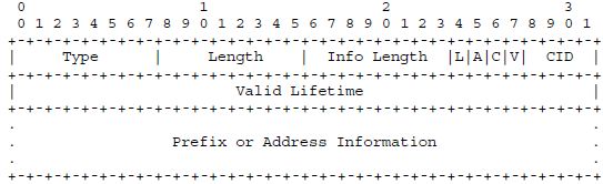
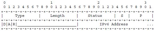
The 6LoWPAN information option (Figure 3.1) has been both simplified and extended with respect to the standard ND prefix information option: the pair of lifetimes that provides a grace period for renumbering in standard ND has been replaced by a single valid lifetime, and the “Reserved2” field has been removed (see Appendix A.3 for the format of the standard ND prefix information option).
As an addition, there is now a space where a four-bit Context ID number (CID) can be given: this makes the prefix supplied also available (under the CID number given) for context-based header compression (see Section 2.6.2). Generally, CID = 0 will be used for the common globally routable prefix of the LoWPAN. Additional 6LoWPAN information options can be used to supply prefixes for frequent correspondents or other context entries that might improve context-based header compression efficiency. If such an additional 6LoWPAN information option is not intended to supply another prefix for the LoWPAN, the A bit will be set to zero, indicating that the prefix given is not to be used for SAA. The C bit indicates that this information option indeed is meant to occupy a position in the context. The V bit will then normally also be set, but in the lifecycle of a context entry V should be left unset both for introducing and in advance of retracting the entry: C = 1 and V = 0 means the context entry is valid for decompression but should not yet, or no longer, be used for compression.
Figure 3.1 6LoWPAN information option.
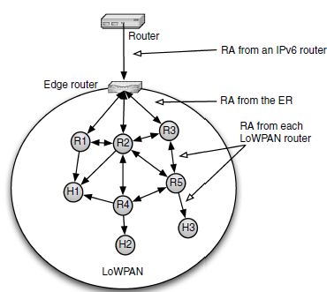
Context-based header compression only works correctly if all nodes in the 6LoWPAN share a common view of the context. 6LoWPAN-ND therefore specifies that the complete set of context is to be disseminated in the entire LoWPAN, starting from the edge routers. The edge routers include the context information in their RAs, making it available to all first hop routers, which disseminate it further down the topology and so on – see Figure 3.2. The sequence number discussed below makes sure that the freshest context information wins even if another router is still sending an old version.
Figure 3.2 Router Advertisement dissemination.
If a large number of entries in the context are actually being used, the 6LoWPAN information options needed to send the entire context in one RA message may be up to 16 × (8 + 16) = 384 bytes in size. Sending all this information in every RA would require fragmentation, compromising the delivery probability (in particular for multicast, which cannot use link-layer acknowledgment) and loading the channel. Therefore, the entire set of 6LoWPAN information options in force at one point in time is assigned a sequence number. This sequence number is included in an RA within the 6LoWPAN summary option – see Figure 3.3. (The sequence number is only valid if the accompanying V bit is set.) The unsolicited RAs that are regularly broadcast by every router only need to contain the 6LoWPAN prefix summary option. If a node notices a change in the sequence number with respect to the information it has, it can request an update by unicasting an RS message to the source of the RA; the router always responds to a unicast RS with an RA that includes the full set of prefix information.
Figure 3.3 6LoWPAN summary option.

The 6LoWPAN prefix summary option also contains an ER metric; we will come back to that in Section 3.2.4.
3.2.2 Registration
In standard ND, the next step after forming an address would be to perform Duplicate Address Detection (DAD) on it. This is done by sending a Neighbor Solicitation (NS) to a solicited-node address, a multicast address formed as a function of the address to be validated.This process only works correctly if multicast packets are likely to reach every node that subscribes to the solicited-node address on the subnetwork, an assumption that cannot be made for 6LoWPAN.
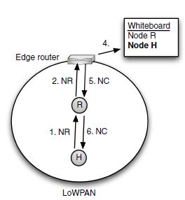
Instead, 6LoWPAN-ND uses the edge routers as the focal point of Duplicate Address Detection. Every edge router maintains a whiteboard on which nodes can scribble their address and which other nodes can later read. This is done using two new ICMPv6 messages: Node Registration (NR) and Node Confirmation (NC); the entire process is accordingly called registration. (A detailed list of the contents of a whiteboard entry will be provided in Table 3.1 in Section 3.2.3.)
Let’s start by discussing the simplest case, a node directly registering to an adjacent edge router. After obtaining a prefix for SAA as well as the address of the edge router, the host attempts to register one or more of its own addresses with the edge router by sending a NodeRegistration message. The edge router replies with a Node Confirmation message listing the addresses that were acceptable and includes those in its whiteboard (see Figure 3.4).
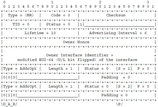
Both the Node Registration and the Node Confirmation message use the format shown inFigure3.5. Note that the formats newly defined in 6LoWPAN-ND attempt to be similar and compatible to the existing ND formats; this has taken precedence over any desire to squeeze out the last couple of redundant bits (the assumption being that these messages occur rarely and are still small enough to avoid adaptation-layer fragmentation). Type, Code and Checksum are as usual in ND messages (we will see how Code is used in the multihop case in Section 3.2.4). TID is a transaction ID, which is used in the detection of duplicate IIDs (see Section 3.2.3). Status is used in NC messages to indicate whether the registration request was successful. The P bit, if set, indicates that this is a primary registration; if unset, the registration serves as a backup with additional edge routers for fault recovery. We will revisit the TID and P fields later in this chapter.
Figure 3.4 Basic router discovery and registration process with an edge router.
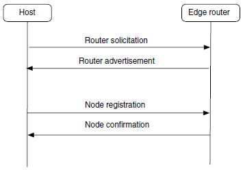
Figure 3.5 Node registration/confirmation message format.
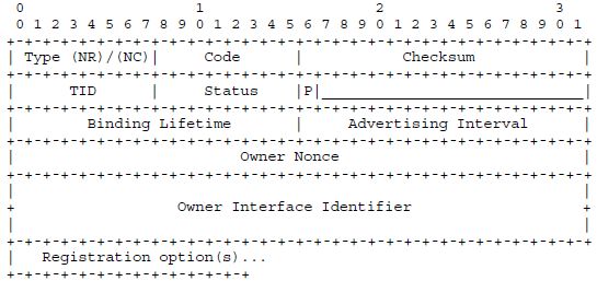
The Binding Lifetime specifies how long the entry (entries) generated in the whiteboardby this request shall remain valid (in minutes; the 16-bit unsigned integer can indicate lifetimes up to about 6.5 weeks). The whiteboard entries, called bindings by analogy to a related mechanism in Mobile IPv6 [RFC3775], are soft state, i.e. they need to be refreshed periodically to remain in place. After the lifetime elapses, the edge router deletes the binding(s) from the whiteboard, which provides 6LoWPAN-ND’s mechanism of garbagecollecting entries that have gone stale. The registering node, the owner of the binding, should therefore refresh the binding by sending another NR message well before the end of the lifetime, analogous to renewing a lease contract. (A second value, the Advertising Interval,describes a lifetime for the relationship of a node to its neighboring router, in multiples of 10 seconds.)
As the penultimate field of the static part of the NR/NC message, the owner of the binding is identified by its owner interface identifier (OII), the IID generated in the usual way (U/L bit flipped) from the EUI-64 of the node. 6LoWPAN-ND generally assumes that OIIs are globally unique (as EUI-64’s should be!), but also provides a mechanism to detect the error case of multiple nodes sharing an OII (discussed in Section 3.2.3; this process is aided by the Owner Nonce).
The rest of the information in the NR/NC messages is carried in ND options, illustrated as binding options in Figure 3.5. Each NR message can request the registration of one or more addresses, and each NC message can confirm the registration of one or more addresses. In order to carry the addresses in one of these messages, each of them is encoded in an address option (see Figure 3.6).
Figure 3.6 Address option format.
Type and Length are as in any ND option. The Status field indicates success (0–127) or failure (128–255) in an NC message and is unused in NR messages. There are flags that modify the request/confirmation:
D: The duplicate flag, if set in an NR, indicates that multiple registrations for one address are acceptable. This is used for registering anycast addresses.
A: The address generation flag, if set in an NR, indicates that the host is not supplying an address (the length of the included IPv6 address is 0 in this case) but that the edge router is requested to generate one. The P and S fields (see below) indicate what kind of address is requested. In an NC, the A bit is set to indicate that the address was indeed generated.
R: The removal flag, if set in an NR, indicates that this particular address is not requested for addition but for removal from the whiteboard. In an NC, a set R flag indicates that the address must not be used any longer.
Finally, P, S and the IPv6 address field compactly encode the IPv6 address to be registered/confirmedwith some compression;P and S also specify the specific type of address requested in case the A-flag is set. The P field specifies the handling of the first 64 bits (the “prefix” part) of the IPv6 address, and S that of the remaining 64 bits (the “suffix”). For P = 16, the prefix is carried in-line in the option. P = 17 is used to indicate the prefix FE80::/64, any value of P between 0 and 15 for the prefix with that Context ID (CID); for P =16,nothingneedstobesentfortheprefix.Similarly,forS=0,thesuffixiscarriedinline in the option. For S = 1, the suffix is elided and instead copied from the owner interface identifier field in the NR/NC message header, and for S = 2, the suffix is constructed from a 6LoWPAN 16-bit short address as defined in the 6LoWPAN format specification (or, if a non-IEEE 802.15.4 radio is in use, “as appropriate for the link layer of the LoWPAN”) sent in-line. The other possible values for P and S are reserved.
The NR/NC message exchangeis best demonstrated by a small example. Let’s assume that a host that is on the same link with an ER wants to register two addresses to the whiteboard, both an address generated from its EUI-64 with SAA and an additional address for which the ER is asked to generate a 16-bit short address (which the host then can also use as a MAC layer address).
To register, the host sends an NR message to the link-local address of the ER. Let’s say the host has just booted, therefore the Transaction ID (TID) starts with 0; a primary registration is requested, the registration is to be valid for a lifetime of 600 s (10 minutes); and the host’s EUI-64, suitably modified, is used as the owner interface identifier.
Figure3.7 shows an NR message for this registration with two address options: one for the address constructed from the Context ID 0 default prefix and the owner IID (in this case, the address is completely compressed away), and one requesting the assignment of a 16-bit short address for the construction of an address from the Context ID 0 default prefix and the newly assigned short address (in this case, the address is not sent with the NR as the A bit is set).
Figure3.8 shows a possible NC message the ER sends in reply. The TID is echoed as 0. The status is 0, so the registration was successful. The lifetime is confirmed as 600 s. The address option for the address constructed from the Context ID 0 default prefix and the owner IID is just echoed and thus confirmed. The second address option confirms the assignment of a 16-bit short address – that address is sent back in the NC with the address option; the host then goes ahead and reconstructs the full IPv6 from the Context ID 0 default prefix and the newly assigned short address.
From now on, the host will regularly re-register before the registration lifetime expires.The re-registration differs in its TID, but also in the way the assigned short address is handled: once the host has been assigned the 16-bit short address, the host simply refreshes the binding for this address; the A bit is no longer set. Figure 3.9 shows how the second address option would look like in an NR message for re-registration (this address option is bitwise identical to an option that would attempt newly registering a 16-bit address obtained in a different way).
Figure 3.7 Example: Node Registration with two address options.
3.2.3 Registration collisions
The whiteboard of an edge router serves as a shared database for all nodes that have registered to that edge router, and, via the mechanisms that hold together an Extended LoWPAN, for the whole LoWPAN. As the LoWPAN is a distributed system, there is always a possibility of multiple nodes trying to create entries in that database that are in conflict with each other.
There are two levels of collision detection in 6LoWPAN-ND:
Address collision detection and resolution. If multiple nodes try to register the same IPv6 address, only one of these registrations should succeed. Each such registration is identified by the pair of the OII and the IPv6 address. A Node Registration that tries to register an IPv6 address that is already registered with a different OII at the same or another edge router is denied, giving the node an opportunity to retry with a different address. This mechanism replaces DAD within a LoWPAN and is useful mostly for ensuring the uniqueness of 16-bit short addresses and the IPv6 addresses built from them.
OII collision detection. The address collision detection and resolution mechanisms are based on the assumption that the OII is globally unique. The way that EUI-64s are allocated is supposed to ensure this in principle. However, if an error in allocating or storing EUI-64s causes two nodes to share an OII, address collision detection breaks down, leading to potentially severe malfunctioning of the LoWPAN. Such manufacturing errors have occurred with Ethernet MAC-48 identifiers, sometimes as a result of counterfeiting. It is therefore prudent to include a mechanism for error detection.
Figure 3.8 Example: Node Confirmation with two address options.

Figure 3.9 Example: the second address option in a refresh NR message.

The assumption of uniqueness of OIIs makes the first of the two, address collision detection and resolution, relatively straightforward. When an NR message comes in, for each IPv6 address given in an address option, the whiteboard is searched for existing bindings for the IPv6 address.
- If there is no such binding, a new binding is created (potentially after checking with other edge routers – see Section 3.2.7), and a positive Node Confirmation message is returned to the node.
Table 3.1 Information content of a Node Registration binding.
| IPv6 address | The IPv6 address being registered by the LoWPAN Node. This is an IPv6 unicast address of any scope. |
| OII | The owner interface identifier of the LoWPAN Node is used for address collision detection and resolution |
| Owner Nonce | The Owner Nonce, as supplied in the last successful registration for this binding. This is used for duplicate OII detection. |
| TID | The Transaction Identifier of the last successful registration for this binding. This is used for duplicate OII detection. |
| Primary flag | Is this edge router the primary ER for the registration? Influences 6LoWPAN-ND operation between edge routers in Extended LoWPANs |
| Age/lifetime | The binding age indicates how long ago the last registration message exchange took place. When the binding age reaches the registration lifetime, the whiteboard entry is discarded |
- If there is such a binding with the same OII, the binding is refreshed with the new lifetime after checking the TID to detect a possible OII collision (see below), and a positive Node Confirmation message is returned to the node.
- If there is a binding with a different OII, we have an address collision, and a negative Node Confirmation message is returned.
Table 3.1 summarizes the information kept by the edge router in a binding.
A more difficult scenario to guard against is the case where two nodes come up in the network that both believe they have the same EUI-64 and thus the same OII, too. As a general observation, it is very hard for other nodes to distinguish between these two nodes unless they add some other distinguishing property such as a random number (which, witha low probability, could also collide!). This is the reason why standard ND makes it the responsibility of each node to find other nodes it is in conflict with – only the node itself can reliably distinguish itself from others. Outsourcing the conflict detection to the whiteboard to avoid the need for multicast requires some way for the whiteboard to detect and reject requests that appear to come from a different node with the same OII as the legitimately registered node. 6LoWPAN-ND supports this with boot-time Owner Nonces, i.e. random numbers that are generated randomly each time a node starts up. The Owner Nonce is used to set up a registration and maintain it; requesting a conflicting registration with a different Owner Nonce points out either a duplicate OII or a node that rebooted and forgot its nonce.
In addition to the nonce, an 8-bit sequence number called the Transaction ID (TID) serves to correlate consecutive messages from one node. The TID is sent in each Node Registration message and echoed back by the Edge Router in the Node Confirmation message. Both TID and Owner Nonce used in the most recent Node Registration message are kept by the Edge Router as part of each binding.
The TID is not quite a normal sequence number, which would be wrapping around from 0xFF (28 − 1) to 0. Instead, after 0xFF, the number continues at 0x10 (16). This leaves the first 16 sequence numbers (0-0xF) for what we will here call rookie bindings, bindings of nodes that have just booted. Such a numbering scheme has been called a lollipop scheme, because it starts with a straight sequence (0-0xF) and continues in a circle from that (0x100xFF to 0x10 again), resembling the shape of a lollipop (see Figure 3.10).
Figure 3.10 The transaction ID (TID) sequence number lollipop.
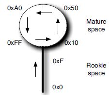
The node increments the TID after sending each Node Registration. When a positive Node Confirmation is received, if the current TID is a rookie value (less than 16), then the node sets it to 16, the first value for a mature TID. So a TID in the straight part of the lollipop denotes a node that just started/restarted and has not yet been registered.
Two TIDs i and k are compared in the following way:
- If i < 16 or k < 16, i.e., one of them is in the straight part of the lollipop, then they compare directly, i.e. a rookie value is always lower than a mature value.
- Otherwise, i.e. both i and k are in the circular part, the usual sequence number arithmetic applies, i.e. i > k if (i − k) mod 28 < (k − i) mod 28.
A TID value is defined to be consistent with the preceding one if one of them could be reached from the other with between 1 and 16 increment operations, i.e. the absolute difference computed analogous to the comparison rules is 16 or less, but not zero.
A Node Registration is consistent with a binding if the TID in the registration is consistent with the TID in the binding, and the Owner Nonces agree. In the normal progress of initial registrations and refreshing re-registrations, the latter should be consistent with the binding.
When a Node Registration message arriving at an edge router matches the OII/IPv6address pair of an existing binding, it is checked for consistency with the binding:
- When the new message is consistent with the binding, it appears that it is coming from the same source as the previous one and there is no OII collision. (If the TID compares as less with respect to the current TID in the binding, but the Owner Nonces agree, then the registration messages apparently were reordered and the newly arrived, but older, message should be ignored, but there is no reason to assume a collision.)
- If the TID jumps down to a rookie value, this can be interpreted as either a new node coming up competing for the existing node’s OII or simply as a reboot by the node owning the registration. 6LoWPAN-ND makes the optimistic (and most likely) assumption that this is a reboot. If there is an actual collision, it will be detected when the old node attempts to refresh its registration.
- If an incoming NR neither has a rookie TID nor is consistent with the binding, then the NR is rejected as an OII collision. (With a conflicting rookie coming in to a running network, this tends to punish the incumbent, not the rookie, but the problem is at least detected.)
In summary, TIDs, enhanced by the nonce mechanism, do protect with high probability against a particular nightmare scenario: a LoWPAN that has been working well for a while develops hard-to-diagnose problems when a single duplicate OII node is coming on line.
Table 3.2 summarizes the message processing rules for Node Registration messages.
Table 3.2 Processing rules for NR messages.

(* = wildcard)
An actual OII collision is one of the situations that in programs are often labeled with “cannot happen”. If it does, there is not necessarily a good way for the losing node to react. It could simply shut down and indicate an error through local means, waiting for human intervention and resolution of the conflict. If a high level of fault tolerance is desired and there is no good way to locally call attention to the error condition, the node could enter an emergency mode by inventing a new EUI-64 for itself using mechanisms akin to those used in the privacy extensions for Stateless Address Autoconfiguration in IPv6 [RFC3041]. This requires stable storage and/or a good source of randomness in the node. It allows the node to communicate (if only to report the specifics of the error), but not necessarily to attain its application layer identity that may also be based on the burned-in EUI-64. In any case, an OII collision is an error caused by a faulty component and should be handled as any other fault in network management.
3.2.4 Multihop registration
The registration process becomes slightly more complicated when the node registering is not adjacent to an edge router. Nodes can also register to a LoWPAN Router in the one-hop neighborhood as long as that router indicates its ability to handle the registration by setting the M flag in its RA. The router then relays the NR to the edge router and the NC back to the node – see Figures 3.11 and 3.12.
At the time that a node sends its first NR message, its link-local address is still optimistic. Therefore, the node sends this NR with the IPv6 source address set to the unspecified address (::). The relaying router takes note of the OII in the NR and the source link-layer address (which, incidentally, should directly map into each other) and uses this state to later relay the NC response from the ER to the correct link-layer address for the node.
Figure 3.11 Router performing ICMP relay on the NR/NC messages.

Figure 3.12 The registration process: multihop operation.
The message format for relayed NR/NC messages only differs from the one used by the hosts in that an alternative code value of 1 is used between relaying router and edge router (note that this change requires an update of the checksum of the message in the relaying router). Even though the NR/NC relaying process is a function of the router, it is not IP forwarding: the Hop Limit of the original host NR is not decremented when relaying.Since there may be multiple edge routers, the relaying job of the router is simplified by using an anycast address for all edge routers: Each edge router configures the well-known 6LOWPAN_ER anycast address as an additional address on the LoWPAN interfaces where it serves as edge router. This means a relaying first-hop router can simply relay all NR messages to that anycast address and let routing take care of all the other hops needed in forwarding the relayed message to an ER. In other words, relaying is, if at all, only performed once at the first-hop router – from there to the edge router normal forwarding of the relayed message is performed.
In IPv4, some ICMP messages were often forged from outside a link to perform some attack such as establishing a redirect. Standard ND therefore requires most messages to be sent with the maximum Hop Limit of 255 and each receiver to check that the Hop Limit is still 255 and was not decremented by some intervening router. As a significant deviation from standard ND, the edge router needs to accept Node Registration messages that were forwarded by other routers on the way from the first-hop router to the edge router and therefore have a Hop Limit value that is lower than 255. To maintain security against outside attacks, the 6LoWPAN-ND specification requires edge routers to detect and drop Node Registration messages that do not come from a LoWPAN interface that is associated to the same LoWPAN.
Given that there may be multiple routers in the one-hop neighborhood available for registration (as is the case with the left-most host in Figure 3.2), which is the best that a host should choose? Obviously, if there is an actual edge router in the one-hop neighborhood, that should be chosen. Edge routers that don’t have a good reason to go incognito identify themselves in their RA messages by setting the default router preference field ([RFC4191], the Prf field in Figure A.9) to high (01 binary); this field is set to medium (00 binary) for RAs from other LoWPAN routers (except for those who don’t have contact with any Edge Router, which send a Preference of low, 11 binary).
But what if none of the routers in the one-hop neighborhood is an ER? This is where the ER metric in the 6LoWPAN prefix summary option comes in handy. The ER metric is a 16bit unsigned integer that can be set by each router to a value indicating how good this router is as a next hop towards the outside world, expressed as some kind of routing cost metric. ERs themselves most likely set this field to 0, as they are by definition the best way out of the LoWPAN. The ER metric is intended to be used by hosts when choosing default routers; they don’t need to understand the semantics of the actual metric (which is likely to derive from the routing protocol in some way – such as a simple hop count in a distance vector protocol). This leaves the hosts oblivious to the details of the routing algorithms used, as they should be. To decide between routers, hosts simply make a scalar comparison of the ER metric value, preferring routers with numerically lower ER metric values. A router with a low ER metric is not only a good default router (assuming most traffic goes outside the LoWPAN), but also is likely to be the best path to an ER that can handle Node Registrations, so the same selection should be made for registration.
In Figure 3.2, the routers in the top-level row close to the edge router (R1, R2, R3) probably can offer a better (lower) ER metric than the routers in the middle row (R4, R5). Host H1, which is adjacent to R1, R2 and R4, is therefore more likely to choose router R1 or R2 rather than router R4 as its default router and as the router to register through.
3.2.5 Node operation
LoWPAN Nodes start operation by autoconfiguring the link-local address derived from the globally unique EUI-64 of the LoWPAN interface (see Section 2.4). From the point of view of Stateless Address Autoconfiguration, the link-local address starts out as an optimistic address [RFC4429] and requires confirmation via an NR/NC message exchange with an edge router before becoming fully operational (preferred). Assuming that the global prefix for the LoWPAN is known at this point, the same NR/NC exchange can also be used to register the address composed of the global prefix and the same modified EUI-64. Finally, the node can go ahead and ask for assignment of a link-layer 16-bit short address from the edge router by registering an address composed of the global prefix and the IID composed from the PAN ID (usually zero) and the 16-bit short address to be assigned, as discussed in the example at the end of Section 3.2.2.
When the Node Confirmation message arrives and indicates success, the node takes note of its new 16-bit short address, adds the corresponding IPv6 address to its LoWPAN interface and changes the status of the addresses from optimistic to preferred. As the bindings established in the edge router by the registrations have a defined lifetime, the node now needsto periodically send new Node Registration messages to refresh the bindings before they run out (it can now use its link-local address as a source address as that is no longer optimistic). If a node does not receive a Node Confirmation on such a refresh message even after retries and possibly trying different first-hop routers, the addresses turn back to optimistic and the registration process needs to be restarted from the beginning.
As a result of the way LoWPAN Nodes generate their IPv6 addresses, there is a oneto-one mapping between (both 16-bit and 64-bit) link-layer addresses and corresponding link-local addresses (see Section 2.4). The same is true for the addresses generated from the global prefix. Other nodes make use of this mapping to find the link-layer addresses for intraLoWPAN IPv6 addresses they want to sent packets to. Therefore, a LoWPAN Node never sends a Neighbor Solicitation for address resolution, which increases power efficiency and reduces implementation complexity.
But how does the node know whether a node with a LoWPAN address is in the one-hop neighborhood or needs to be addressed via a router? In a Route-Over LoWPAN, prefixes are not assumed to enable on-link decisions (the L bit is not set for prefixes announced in Router Advertisementsin Route-Over LoWPANs). Instead of just the prefix, all the bits of the specific destination address are important for the on-link decision. The node may have cached information about its one-hop neighborhoodfrom previous packets received. Or it might even optimistically attempt to transmit a packet directly to the link-layer address derived from the IPv6 destination address. The more usual node behavior is to send the packet to the default router selected via the ER metric criterion in the absence of any such cache entry.
LoWPAN Nodes do not send Neighbor Solicitations for Neighbor Unreachability Detection (NUD) either. Instead, the procedure recommended by the 6LoWPAN format specification applies: link-layer ACKs may be used to detect whether the packet arrived. If no acknowledgment is received after an appropriate number of retransmits, the node might delete the supposed neighbor from its one-hop neighborhood cache and retry by sending the packet to the link-layer address of its default router.
The 6LoWPAN-ND specification therefore says that the implementation of support for Neighbor Solicitation/Neighbor Advertisement messages by a node is entirely optional; as this in turn means that a LoWPAN Node cannot rely on them being implemented by another node, the messages are indeed not very useful and it is likely that few 6LoWPAN implementations will support them at the LoWPAN host or router level.
More than NUD, routing plays an important role in getting packets to their destination in a LoWPAN. LoWPAN Routers or edge routers send ICMPv6 destination unreachable messages to indicate that delivery to a destination is not possible; nodes should therefore support processing of these messages (ICMP Type 1) [RFC4443].
In addition to unicast addresses, nodes need to support the all-nodes multicast address (FF02::1), as this is used for receiving RAs from routers. Support for other multicast addresses is not required for hosts by 6LoWPAN-ND. Multicast addresses are always considered to be on-link and are resolved as specified in the 6LoWPAN format specification (see Section 2.8).
3.2.6 Router operation
A LoWPAN Router begins operations like any other LoWPAN Node: it sets up its interface(s) and their addresses, and to perform the required Duplicate Address Detection using the whiteboard, it first needs to find an edge router or another router that has a path to the edgerouter.
Once the interfaces are set up, the router can start running the routing protocol that it is configured to use; once that has stabilized, it can advertise its services to other nodes usingperiodic Router Advertisements and by listening to Router Solicitations.
The network configuration parameters that a LoWPAN Router announces in Router Advertisements are copies of the ones it received during its own bootstrapping. As a result, these parameters originate at the edge routers. A LoWPAN Router must continue to pay attention to Router Advertisements that it receives and update its parameters whenever the sequence number in the 6LoWPAN prefix summary option increases (in the sense of the usual sequence number arithmetic). As a result, new values advertised by the edge routers flood the LoWPAN and are eventually disseminated to all routers and hosts within the LoWPAN.
Apart from its usual duties as a router, a LoWPAN Router needs to relay Node Registrationmessages from adjacent nodes to an edge router and relay back Node Confirmation messagesto the originating node. In a Node Registration message received, the router sets the Code field to 1 to indicate that the message is being relayed, sets the IPv6 source address to its own LoWPAN address, recalculates the checksum, and sets the Hop Limit to 255. Usually, it then sends the resulting message to the 6LOWPAN_ER anycast address (a different address or set of addresses may be configured).
Nodes that are in the process of bootstrapping send their initial Node Registration messages with the IPv6 source address set to the unspecified address (::). In order to have a way to relay the Node Confirmation, the router keeps state regarding the originating node’s OII to link-layer address mapping while waiting for the Node Confirmation to come back from the edge router. Once that arrives, it sets the code back to zero, sets the Hop Limit to 255, and (if the NR came from the unspecified address) uses the state to derive the link-local IPv6 destination address as well as the link-layer destination address to be put into the relayed NC. This is also a good time to cache that mapping in the router’s neighbor cache.
3.2.7 Edge router operation
Most LoWPAN Nodes have exactly one interface through which they run their entire communication. The edge router is different: it also has an interface into a larger IPv6 network. As shown in Figure 1.7, this can be a simple backhaul link to some infrastructure unrelated to the LoWPAN, making the LoWPAN a Simple LoWPAN, or it can be a backbone link connecting to other edge routers in the same Extended LoWPAN. Obviously, the lattercase requires significant coordination between the edge routers.
Let us start with the case of a single edge router. Again, this is a LoWPAN Router, but with additional duties:
- The edge router is the source of the network parameters disseminated in the Router Advertisements, including the LoWPAN prefix and the other context entries for the context-based header compression. Generally, edge routers will therefore require some configuration, while normal routers and hosts can bootstrap off the Router Advertisements, once commissioning parameters have been set.
- The edge router has to run the whiteboard and the two conflict detection algorithms.
- The edge router performs the routing from other IPv6 networks into and back out of the LoWPAN. To do this, it needs to run its other interfaces and possibly additional routing protocols over them. The edge router also has some protection duties in performing this forwarding: it filters out certain ICMP messages to prevent Neighbor Discovery-based attacks, and it only forwards packets into the LoWPAN for LoWPAN addresses that have been registered in the whiteboard, relieving the LoWPAN routing protocol from possibly expensively searching for a route to a node that does not exist. The system implementing the edge router function may, of course, implement other protection functions, such as a firewall or other kinds of packet filtering.
Support for Extended LoWPANs is optional in edge routers. In an Extended LoWPAN, multiple edge routers are interconnected with a backbone link, usually a higher speed, fully multicast-capable link such as an Ethernet. The backbone link has the same prefix as the LoWPAN, requiring the edge routers to bidirectionally translate between 6LoWPAN-ND on the LoWPAN interfaces and standard ND on the backbone link.
In an Extended LoWPAN, the collision detection algorithms are extended over the backbone link, using the standard ND protocol messages Neighbor Solicitation and Neighbor Advertisement. In effect, each edge router represents not only itself in the standard ND protocol, but also the collection of node addresses registered to it, much like a Mobile IPv6 home agent would for its mobile nodes’ home addresses. Neighbor solicitations on the backbone link are answered by the edge routers (or other nodes on the backbone link), they never propagate into the LoWPAN. This requires that edge routers must join the solicitednode multicast addresses on the backbone link for all the registered addresses of the nodes in their LoWPANs and answer any Neighbor Solicitation with a Neighbor Advertisement that indicates the edge router’s own backbone link link-layer address in the target link-layer address option.
LoWPAN Nodes moving between parts of the LoWPAN (whether by their own physical movement or by router movement or changing radio characteristics) and then sending NR refreshes to the 6LOWPAN_ER anycast address may start to reach a different edge router from the one they previously were registered with. The new edge router then simply takes over the registration, keeping the LoWPAN Node mostly oblivious to this transition. The old edge router (that had the registration previously) surrenders the registration to the one where the new NR message arrives – see Figure 3.13. Between the edge routers, on the backbone link, standard ND messages such as Neighbor Solicitation (NS) and Neighbor Advertisement (NA) are used. To enable the use of owner interface identifiers (OIIs) and transaction IDs (TIDs) in the conflict detection algorithms even over the backbone link, the NS/NA messages are extended with the owner interface identifier option, an option that is only used on the backbone link, never within the LoWPAN – see Figure 3.14.
Figure 3.13 Extended LoWPAN operation as a binding moves to a new edge router.
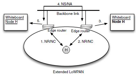
Figure 3.14 Owner interface identifier option.

One important aspect of setting up a LoWPAN is establishing and maintaining its security. Wireless networks by their nature are wide open to attackers, who may overhear and inject packets being exchanged, possibly using advanced antenna technology to mount their attacksfrom well outside the normal range of IEEE 802.15.4 devices.
The merits of the Wireless Embedded Internet will not just be decided on technical grounds. As the proponents of consumer RFID have experienced, a few well-publicized security and privacy incidents can seriously damage the future of an emerging technology.
Another technology that took significant early damage was IEEE 802.11, which was initially designed with the assumption that weak security would be enough, under the name “wired equivalent privacy”. Starting out with a compromised model is a recipe for disaster, which in this case was complementedby mistakes in implementing the model. There is a large and inventive community of security researchers (both white-hat and black-hat!) that will quickly uncover problems with any widely deployed security mechanism. Even after a quite secure version of IEEE 802.11 (IEEE 802.11i, also often referred to as “wireless protected access 2” WPA2) was established, the notion of a hard-to-protect protocol stays around as a part of the public image of IEEE 802.11, still remaining an obstacle to its deployment especially in the enterprise space.
3.3.1 Security objectives and threat models
A system cannot be called secure unless the security objectives have been defined that are being claimed to be fulfilled. These can often be grouped into three categories:
Confidentiality. Data cannot be overheard by unintended listeners, i.e., remains secret except for the authorized participants of the conversation. This is often not possible in a literal sense, but can be achieved in effect by making the information unintelligible by cryptographic encryption.
Integrity. Data cannot be altered by unauthorized parties, i.e. the data that is being received by an authorized participant is identical to the data that was sent by another participant. In a digital world, tampering with a message may not leave any detectable traces, so integrity is often achieved by adding cryptographic integrity checks to messages. Since an unaltered message from a fake sender can have the same effects as a message from the intended sender the contents of which has been tampered with, a related security objective is that of authentication: a message actually is originating from the source that it claims to be. A message integrity check is therefore often the same thing as message authentication.
Availability. The system is not subject to denial of service attacks. Note that any wireless system is subject to jamming at the radio level; however, such a jammer in a very localized network should be comparatively easy to locate and take out of service. More dangerous would be denial of service attacks from sources that cannot be easily controlled, such as the infamous “ping of death” packet that could be sent from anywhere (possibly with a fake source address) to crash certain buggy operating systems.
These security objectives may derive directly from application requirements, e.g., a factory automation system usually has very strong integrity and availability requirements, along with more or less stringent confidentiality requirements. However, security objectives can also result from the internal workings of a system: even if the data being processed in a LoWPAN are entirely public, a security element necessary for integrity that is based on a password or other secret creates an additional security objective: the confidentiality of that password.
Once the security objectives are defined, we need to understand the threat model: what is the attacker going to be able to do that might work against the security objectives. An important subquestion is the level of benefit that the attacker may derive from subverting a security objective. This may have a bearing on the amount of resources that the attacker can deploy. (The threat model for a bank is quite different from that for a vending machine although both are mainly attractive targets for the money they store.)
The threat model for wireless systems such as 6LoWPAN is not much different from the general threat model assumed for Internet security protocols, the Dolev-Yao model [Dolev81, RFC3552]: the attacker is assumed to have practically complete control over the communications channel. The attacker can read any message, remove (suppress) and change existing messages, as well as inject new messages. Again, without cryptographic support, there is no way to protect messages from reading or to detect a message that has been tampered with.
The Internet threat model assumes that end systems have not been compromised, mainly because it is very hard to maintain full security if that assumption cannot be made. However, the small size and distributed nature of the LoWPAN Nodes creates a rather significant threat here: in many LoWPAN deployments, it will be relatively easy to physically obtainand control at least one node in the network; the low-cost requirement will limit the level to which the nodes can be made tamper-proof. (In any case, a compromised temperature sensor can be used to inject false temperature readings by “hacking” it on the digital level or trivially by changing its temperature!) Still, measures should be taken to control the damage. In particular, it is an importantadditional requirementthat the protection of the entire networkdoes not depend on the integrity (and confidentiality of the memory) of each and every single node. Note that this creates hard problems, and it is therefore important to strike a balance between the potential damage and the cost of providing and maintaining the security.
3.3.2 Layer 2 mechanisms
The end-to-end principle [SRC81] argues that many functions can be implemented properly only on an end-to-end basis, such as ensuring the reliable delivery of data and the use of cryptography to provide confidentiality and message integrity. Adding a function to improve reliability on a particular link may provide some optimization, but can never ensure reliable delivery end-to-end. Similarly, security objectives that can only be met by protecting the conversation between two end-nodes are therefore best met by performing the cryptography at layer 3 or higher (see Section 3.3.3); there may even be security objectives that require protecting the data itself instead of the communication channel.
However, this does not mean that all security objectives can be met end-to-end. In particular, achieving robust availability often requires protecting the subnetwork against attackers, more so for wireless networks. Adding a first line of defense at layer 2 may also increase robustness against attacks on confidentiality and integrity. (Occasionally, there may even be a good argument that the protection against eavesdropping and forgery are already “good enough” on the wired segments of a path, suggesting that providing confidentiality and integrity just on the wireless layer 2 may be sufficient. Let’s just say that this tempting argument withstands scrutiny much less often than it initially seemed attractive on a napkin.) Not unlikely as a reaction to the early IEEE 802.11 security tribulations, IEEE 802.15.4 requires the support of rather strong cryptographic mechanisms from each node, a requirement that is fully met by most of the IEEE 802.15.4 chips available today. The encryption mechanism chosen is based on the modern algorithm AES (advanced encryption standard [AES]), which was selected by the international cryptographic community as a successor to the outdated DES (data encryption standard) in an extensive international competition between a number of strong and survivable candidate algorithms. IEEE 802.15.4 uses AES in the counter with CBC-MAC (CCM) mode [RFC3610], which provides not only encryption but also an integrity check mechanism.
When combining encryption with authentication, some of the authenticated information may have to be sent in the clear. AES/CCM therefore encrypts a message m and authenticates that together with (possibly empty) additional authenticated data a, using a secret key K and a nonce N. A parameter L controls the number of bytes used for counting the AES blocks in the message; m must be shorter than 28L bytes. For IEEE 802.15.4packets, the smallest value of L = 2 is plenty. The nonce N is of length 15 − L, i.e. 13 bytes for IEEE 802.15.4. The nonce is not secret, but must be used at most once: If an attacker has access to two messages encrypted with the same K and N, the security properties of AES/CCM are lost. The result of AES/CCM is an encrypted message of the same length as m as well as an authentication value of length M bytes, where M is a parameter that can be any even value between 4 and 16 in [RFC3610], but is restricted and extended to one of 0 (no authentication), 4, 8 or 16 bytes in IEEE 802.15.4. The authentication value can only be created correctly if K is known, so it can be checked by the receiver to ensure that m and a have not been tampered with by an unauthorized party.
AES/CCM is a quite efficient and very secure algorithm, as long as the same nonce N never occurs twice with the same key K. IEEE 802.15.4 builds the 13-byte nonce from the eight-byte full address of the device originating the encrypted frame (L2 packet), a four-byte frame counter, and a one-byte field occupied by the IEEE 802.15.4 security level. Appendix B.3 shows the packet subheader format involved.
So how does IEEE 802.15.4 ensure that a nonce is never used twice? The source addressand security level surely repeat. So the security of the entire scheme rests on the four-byte frame counter. This allows sending up to 232 encrypted frames from one source before the key that was used for these frames is “used up”, assuming that the node has some stable storage that saves the current frame counter reliably even across node resets. At the currentmaximum IEEE 802.15.4 speed and with an assumed average frame size of, say, 32 bytes, this means that a node monopolizing the channel can do that securely with a single key for about 222 seconds or about seven weeks. Even if a model based on continuous transmissionresults in a lower bound of key lifetime, it is clear that many applicationswill require rekeying within the lifetime of the system deployed.
Even if that were not the case, it is very hard to ensure that every node reliably stores the highest sequence number ever used from its EUI-64. Note that if that knowledge is lost, the key K (or the EUI-64!) has to be changed to remain secure. ISA100 (see Section 7.1) follows a slightly different approach by encoding the current TAI (international atomic time) in units of 2−10 seconds into four bytes of the nonce and using the last byte as a sequence number (which is unlikely to increase very much during one 2−10 second tick).
This makes 222 seconds a hard limit of the key lifetime, meaning that new keys need to be deployed at least about every month or so. On the other hand, if reliable (and secure!) time synchronization can be achieved, this frees the nodes of the need to store the highest spent frame sequence number.
3.3.3 Layer 3 mechanisms
Even with the best link-layer security mechanisms in the LoWPAN, the data is no longer protected once it leaves the link. This makes the data vulnerable at any point that is responsible for forwarding it at the network layer, or on any link that has lesser security. Worse, an attack on the network layer might be able to divert data onto a path that contains additional forwarding nodes controlled by the attacker.
End-to-end security that protects the conversation along the entire path between two communicating nodes is therefore an important element of any robust security system, so much so, that this requirement became a banner feature in the development of IPv6. The resulting security functions have been ported back to IPv4 and are independent enough of the IP version that they are known as IPsec [RFC4301].
IPsec has two main components: packet formats and related specifications that define the confidentiality and integrity mechanisms for the actual data, and a key management scheme called IKE (Internet key exchange [RFC2409], updated by IKEv2 [RFC4306]). The relatively complex set of protocols that constitute IKE is generally considered a poor fit for the requirements of LoWPANs, so we will not discuss it here; see Section 3.3.4 for some considerations on alternative schemes for key management.
IPsec defines two packet formats for cryptographically protected data: the IP authentication header (AH) [RFC4302], which provides integrity protection and authentication only, and the IP encapsulating security payload (ESP) [RFC4303], which combines this function with confidentiality protection through encryption.
AH got a bad name with IPsec implementations for IPv4, as it protects not only its payload but also the addresses in the enclosing IP packet header. This detects and rejects the tampering with IP addresses performed by NATs, which are essential to the operation of IPv4 networks.Although AH is perfectly useful in the NAT-free IPv6 environments, this problem has led most IPsec implementers to focus on ESP, which we will do here, too.
Figure 3.15 shows the ESP format. In contrast to other IPv6 extension headers, which simply precede their payload, ESP encloses (“encapsulates”) it, which is somewhat logical, given that the payload is encrypted. The part of the format marked “C” on the right is encrypted (confidentiality protected), the larger part marked “I” is subject to integrity protection.
The security parameters index (SPI) identifies the specific security parameters, includingthe keying material, used for this direction of the conversation (security association). For unicast packets, the SPI is an identifier of local significance to the receiver, i.e. it is assigned by the receiver in a way that facilitates its local processing of the incoming ESP packets. The sequence number is an unsigned 32-bit number that increases by one for each packet sent on the security association; it can also be the lower 32 bits of a 64-bit sequence number kept inthe security association. The payload data, together with the trailer consisting of the padding, the pad length and the next header field, are the part of the packet that is encrypted; what is shown in the figure is the unencrypted/decrypted version of the data.
Figure 3.15 Encapsulating security payload (ESP) packet format.

The next header field specifies how the decrypted data is to be interpreted by the receiver.It can identify the payload as an IP packet (tunnel mode) or as some transport data such as a UDP header followed by a UDP payload (transport mode). Tunnel mode is most useful for security gateways (“VPN gateways”); transport mode is a more compact way to obtain end-to-end security as no second IP header needs to be sent.
The padding (the length of which is given by the eight-bit pad length field) can be added to round up the length of the payload and trailer (including pad length and next header) to a multiple of four bytes, which is the minimum required alignment of the beginning of the ICVfield. (Actually, the encryption algorithm might pose more stringent alignment requirements, such as a full AES block of 16 bytes for modes such as AES-CBC [RFC3602]; this is not an issue with streaming modes such as the AES-CCM most likely used in LoWPANs.)
Finally, the integrity check value (ICV) is used with the other information in the ESP header, payload and trailer to check the integrity of the packet. The length of the ICV is defined in the security association.
LoWPAN Nodes are likely to have hardware for AES/CCM encryption, decryption and integrity check processing. This hardware is generally available in a way that allows software above the link layer to use it, making AES/CCM for ESP [RFC4309] the obvious candidate for the cryptographic suite used to achieve end-to-end confidentiality and integrity/authentication.Figure 3.16 shows how the encrypted payload and the ICV look with AES/CCM. The encrypted payload starts with an explicitly transmitted initialization vector (IV) of eight bytes. (This is prepended by three bytes of salt in the security association to produce an 11-byte nonce going into the CCM algorithm – the AES/CCM for ESP transform uses CCM with L = 4 to provide support for very large jumbograms.) The encrypted payload follows (the payload has been fitted with a trailer before encryption, appropriately padded to a multiple of four bytes). Finally, the ICV is appended. [RFC4309] provides for ICV sizes of eight bytes and 16 bytes as well as optionally 12 bytes; which of these values is used needs to be defined in the security association.
Figure 3.16 ESP payload encrypted with AES/CCM.

In summary, it can be said that ESP with AES/CCM is not necessarily too heavyweight for end-to-end encryption and integrity checking between a LoWPAN and its correspondent nodes. With most IEEE 802.15.4 capable chips, the processing overhead is as small as it possibly could be. The per-packet overhead could be a bit less with 1–4 bytes of overhead for padding (including pad length) and eight bytes for the explicitly transmitted initialization vector (IV), but it is not too bad, if solid end-to-end cryptographic protection is indeed needed. (If more efficiency is really needed, a special version of the AES/CCM transform could be defined that creates even less overhead, or preferably some special form of stateless header compression could be added to LOWPAN_NHC, e.g. by deriving the initialization vector from other information present in the MAC-layer packet.)
3.3.4 Key management
One lesson was really driven home by the IEEE 802.11 WEP disaster even before all of WEP’s cryptographic security flaws surfaced: a single key shared by all devices on the network and essentially unchangeable without touching all these devices does not scale. Larger WLAN sites quickly abandoned WEP for L3-based security (“VPNs”) or enhanced the L2 key management by schemes based on 802.1X and finally 802.11i.
While the username/password-based authentication schemes usually used with 802.11i “enterprise” style WLANs are not really applicable to 6LoWPAN, it is worthwhile looking at the key management aspect. At the end of the EAP-based authentication, the WLAN station and the WLAN access point share a secret, the pairwise master key (PMK). However, thisis not used for actually encrypting traffic: the two devices then go on to derive a pairwise transient key (PTK) from the PMK. A new PTK is derived by the devices whenever the existing one is “spent” cryptographically.
In addition to the pairwise key useful for unicast traffic between WLAN station and WLAN access point, each WLAN access point creates a random group transient key (GTK) in order to be able to send broadcast frames to all WLAN stations associated with it. The GTK is usually changed with a period of a couple of hours and sent to each station via unicast using the established pairwise keys.
The specific key management scheme used here is not easily adaptable to 6LoWPAN as the situation in a WLAN is quite different: the WLAN infrastructure is essentially composed of WLAN access points (think edge routers), connected via Ethernet (think backbone link) which is usually outside the WLAN security considerations. WLAN stations directly associate with a WLAN access point. Also, the processing, storage, power and user interaction capabilities of WLAN nodes are usually beyond those of 6LoWPAN devices.
However, the example is useful to illustrate some key concepts of key management:
Long-term keys like the PMK are never directly used for encrypting traffic. Instead they take part in relatively infrequent cryptographic operations such as rekeying that result in short-term keys. (In 802.11i, the PMK is not really long-term as it is produced by each new authentication, except when the WLAN is in pre-shared key (PSK) mode.)
Short-term keys like the PTK are used to actually encrypt traffic. They can be efficiently replaced once their cryptographic power has been used up, e.g. by applying key derivation functions to some long-term keys and some nonces exchanged securely.
Pairwise keys are used between two entities to encrypt and authenticate. The resulting authentication is strong, as one of the entities can be pretty sure the other one sent the data if it wasn’t itself.
Group keys are used for functions such as broadcasting. The resulting authentication is relatively weak, as one of the entities can never be sure whether the claimed source sent the data or some other member of the group, all of which know the key.
At the time of writing this section, one can only speculate about the ways these concepts will be used in LoWPANs. In an ISA100 context, there is a special security manager that is responsible for performing all key management. Devices are provisioned with join keys that are then used to obtain shorter-term keys such as a link-layer group key and transport layer pairwise keys from the security manager. However, at the link layer, the communication for the join process is “protected” only by a well-known key, opening up the protection of the network.
Let’s end this section with simply repeating its main take-home message. As has been amply demonstrated by WEP, it is not a good idea to continue using a key over and over, especially with stream ciphers like WEP’s RC4 or IEEE 802.15.4’s AES/CCM. CCM completely loses its security if the same IV value is used more than once for a given key. [RFC4309, section 9] therefore rightly admonishes the reader not to use AES/CCM with statically configured keys: “Extraordinary measures would be needed to prevent the reuse of a counter block value with the static key across power cycles. To be safe, implementations MUST use fresh keys with AES CCM.” A key management scheme is required in order to be able to properly take advantage of IEEE 802.15.4’s superior security technology.