
7
System Examples
In this chapter we look at how 6LoWPAN is used as a part of complete systems. We introduce the ISA100 standard for industrial automation systems, along with two commercial systems that use 6LoWPAN. By analyzing real systems we can put wireless communication and 6LoWPAN networking issues into a practical perspective, looking at where and how 6LoWPAN and related protocols are used. Often the best way to understand the real potential of embedded networking technology is to dig into an application area, which usually reveals a surprising number of uses. The case of facility management introduced in Section 1.1.5 is a good example of this. At the same time, 6LoWPAN networking is only one piece of the embedded system, which often consists of a large number of subsystems and communication technologies. When making a commercial system using wireless IP networking technology, especially when dealing with embedded devices and systems, there are a number of issues that must be faced that aren’t necessarily explained in standards – including for example installation cost, ease of use, user privacy and system security.
Industrial automation requires a holistic system approach as there are special requirementsfor QoS, safety and security. The integration of wireless industrial field devices with backend supervisory control and data acquisition (SCADA) systems requires careful planning. In Section 7.1 we introduce the ISA100 standard, which defines a complete system solution to wireless industrial automation using IEEE 802.15.4 and 6LoWPAN standards.
Building automation is an important application area for the Wireless Embedded Internet.In the following sections we introduce two examples of commercial systems developed to solve different aspects of automation in buildings. In commercial buildings of all kinds, access control is an important activity for the operator of the building. Traditionally access control was dealt with using people and physical keys, but most modern buildings are equipped with radio frequency identification (RFID) access control systems (also commonly retrofitted in older buildings). In Section 7.2 we introduce a commercial system for RFIDbased access control that uses 6LoWPAN to provide a wireless network between access control devices, instead of traditional wiring of all access control components.
In Section 7.3 we look at energy savings in buildings through improved building management and real-time knowledge of how much energy is being consumed by appliances. Governmentalstudies have shown that a large percentage of energy is consumed as electricity or heat in buildings, of which a substantial portion goes to waste. A commercial system using 6LoWPAN networking is introduced that enables real-time information collection about energy consumption and better building management practices.
7.1 ISA100 Industrial Automation
ISA100 is a new standard for wireless industrial automation systems [ISA100]. It is backed by the International Society of Automation (ISA), which is accredited by ANSI. ISA is an international non-profit organization made up of 30,000+ automation professionals. ISA100 is one of a number of standards that include SP95 for enterprise control systems, ISA99 for security, SP50 that documents the Foundation Fieldbus, and a host of other standards for the industrial networking space. ISA100 is not a single standard, but is expected to be part of a family of standards designed to support the wide range of wireless industrial plant needs to include process automation, factory automation and RFID. The core wireless automation system of ISA100 is standardized as ISA100.11a.
Specifically for non-critical monitoring, alerting and supervisory control, ISA100.11a has been designed to support these and the needs of process control where latencies on the order of 100 ms can be tolerated. The standard defines the protocol stack, system management and security functions for use over low-power, low-rate wireless networks (currently only the IEEE 802.15.4 standard). 6LoWPAN standards are utilized for networking.
The design goals for ISA100.11a were:
- an open standard
- simple to use and deploy
- serve industrial and process control
- assure multi-vendor interoperability
- support and utilize existing open standards
- coexist with existing installed wireless networks
7.1.1 Motivation for industrial wireless sensor networks
Numerous protocols and networks already exist in the industrial process control space such as Foundation Fieldbus, Profibus, HART, CIP and others. Most all of these use various forms of wired networks to attach the sensor and control/actuator devices together. The cost of installing and maintaining the wiring for these networks is becoming prohibitive, especially as the size of the plants grow and the operators wish to increase the number of monitor points. In one case, the industrial plant that was used as part of the use-case requirements was over 20 square miles in area and had tens of thousands of sensor points. The operators of these plants want a lower-cost (calculated over the total cost of ownership – TCO) solution as compared to wired networks. The TCO in this case includes the devices, physical media, cost of installation, cost of commissioning, device and media maintenance, and ease of expansion. Additionally, they require interoperability between devices from different vendors as well as coexistence with existing networks and technologies. A standards-based wireless solution would provide this lower cost, interoperability and also the ability to greatly increase the number of control and sensor points, providing more information to plant operations which will improve the productivity and safety of the plant.
There are two distinct application areas within industrial automation – process control and factory automation. Process control will typically deal with petroleum, chemical or gas production, and factory automation with manufacturing such things as appliances, discrete components and consumer products. The typical sensor network application for both segments will be for data collection including device monitoring – for example sensing motorvibrations or temperature – and asset tracking. Systems will be deployed to capture some process monitoringfor non-criticalprocess control events, such as environmentaltemperature control and recording for regulatory compliance. It isn’t expected that these wireless sensor nodes will replace existing wired nodes or be used in critical process control applications. They will instead be used to augment the condition monitoring and for expansion to include controlling devices that were not previously connected.
To further ease the deployment and increase the number of installed sensors, support for long battery-life is required. While these devices may transmit messages at an interval of one per second, more typically the average will be one message per minute with only tens of bytes of data per message. Additionally, some devices may transmit stored log files or time-series data on a daily basis that could be tens of kBs of data. Multiple wireless networks may be deployed within the same location with overlapping RF communications. In most cases these will be distinct and separate networks with no need to communicate between nodes on each.
7.1.2 Complications of the industrial space
The industrial space provides some unique challenges for wireless sensor networks. Within the industrial market there are six different classes of sensor and control applications ranging from critical safety (class 0) to condition monitoring and regulatory compliance (classes 4 and 5); Table7.1 gives an overview and some examples of the various types of applications for each class. ISA100 was designed primarily for class 4 and 5 applications, but the architecture will also provide support for class 2 and 3 (control) applications. The major difference between the classes is the latency and timing requirements. As the class numbers decrease the latency, timing and jitter requirements increase, i.e. only small latencies and jitter can be tolerated.
The need for lower and tighter controlled latencies while at the same time providing support for bursty bulk data transfers over shared media necessitates the use of some form of bandwidth allocation over the available channels and time. A typical closed loop control system will require latencies around 10 milliseconds with the added constraint that if packets are not received “in time” the process system will initiate a shutdown. In an open loop(human intervention) control system the required latency needs to be below 150 milliseconds to provide the necessary responsiveness. It was felt by the ISA100 design team that a simple CSMA/CA algorithm, typically used by 802.15.4 devices would not suffice. A more complex graph routing based on time division multiple access (TDMA) with bandwidth and throughputcontracts was used instead. This was also chosen in part because the typical traffic uses a “publish/subscribe” model where data is sent (published) from the sensor devices to one or more systems (subscribers). The application layer publish/subscribe paradigm was discussed in Section 5.3.3.
Table 7.1 Classes of sensor and control applications.
| Class 0 | Safety | Emergency action required |
| • Emergency Shutdown | ||
| • Automatic Fire Control | ||
| • Leak detection | ||
| Class 1 | Control | Closed loop control – Critical |
| • Direct control of actuators, pumps and valves | ||
| • Automated shut-down | ||
| Class 2 | Control | Closed loop control – Non-critical |
| • Optimizing control loops | ||
| • Flow diversion | ||
| Class 3 | Control | Open loop control – Human intervention |
| • Operator performs manual adjustment | ||
| Class 4 | Monitoring | Alerting – Necessary maintenance |
| • Event based maintenance | ||
| • Low battery | ||
| • Vibration monitoring | ||
| • Motor temperature monitoring | ||
| Class 5 | Monitoring | Logging – Preventive maintenance |
| • Preventive maintenance records | ||
| • History collection |
7.1.3 The ISA100.11a standard
The ISA100.11a committee reviewed available protocols before embarking on the design of a new protocol. Specifically the group looked at Wireless HART and ZigBee as potential solutions, but both had significant shortfalls. Some of the design criteria included:
- reliability (enhanced error detection, frequency hopping)
- determinism (TDMA, QOS support)
- security
- optimization for sensor data flows
- support for multiple protocols
- support for multiple applications
- use of open standards
Whereas wireless HART was also designed for industrial wireless sensor networking applications and does provide some of the same features as ISA100.11a, it does not support multiple protocols. Wireless HART only specifies and supports the transmission of HART messages over a wireless physical media. Wireless HART and HART were designed for process control. They were not designed to support additional applications such as factory automation.
ZigBee supports wireless control and battery-powered operations, but it does not provide the necessary QoS support to enable the latency and message flow determinism required for industrial applications. ZigBee also only supports ZigBee messages and would not be able to support other protocols such as HART, Modbus, Foundation Fieldbus and Profibus. And finally, ZigBee was developed and is maintained by a closed special interest group (SIG) and is not an openly available international standard.
There are numerous other proprietary network architectures and protocols that have been deployed and are being deployed, but they generally fail to meet some of the design criteria and specifically fail to meet the requirement of being an open standard.
A typical ISA100.11a network is shown in Figure 7.1. The network design in the figure attempts to show the tree nature of the ISA100.11a architecture. Since much of the traffic is expected to flow from bottom to top in the figure, a tree provides the most efficient topology for such a network. Note that the ROLL routing protocol covered in Section 4.2.6 assumes a similar topological design. There is little or no requirement for node-to-node communications, except to forward packets to the plant network and the control system. The solid and dashed lines in the figure show multiple routing graphs supported by this network.
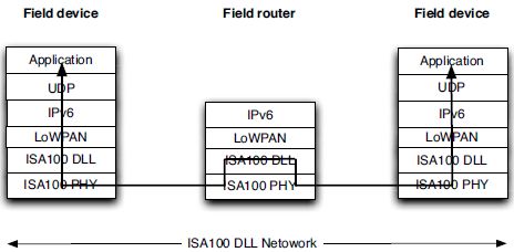
ISA100.11a is based on international standards. The PHY and MAC layers are version 2006 of IEEE 802.15.4 and the network and transport layers are based on 6LoWPAN [RFC4944, ID-6lowpan-hc, ID-6lowpan-nd], IPv6 [RFC2460] and UDP [RFC0768]standards. The ISA100 data link layer implements the graph routing and TDMA features of the standard. The forwardingof messages within the wireless network is performedat the link layer, i.e. using a link-layer Mesh-Under design – see Figure 7.2. Link-layer mesh forwarding under the LoWPAN adaptation layer was discussed in Section 2.5. Future versions of ISA100 may also support the ROLL routing protocol, as it has been designed to support similar requirements in [ID-roll-indus].
Because ISA100.11a leverages IPv6 protocols and addressing, it also uses similar terminology. All of the nodes connected within a single link-local mesh or PAN are collectively called a DL subnet (data link subnet). As can be seen in the figure, packets are forwarded between nodes at the ISA100.11a data link layer. Until a packet reaches either the destination node within the DL subnet or the border router, it does not get interpreted by the LoWPAN adaptation and IP layers. Messages are forwarded within the DL subnet transparently to the upper layers. As a result, the ISA100.11a data link layer provides an abstraction of a broadcast-type network to the higher layers. The ISA100.11a network supports:
- mesh, star-mesh and star topologies
- non-routing sensor nodes
- connection to a plant network via a gateway
- device interoperability
- data integrity, privacy, authenticity, replay and delay protection
- coexistence with other wireless networks
- robustness in the presence of interference
- networks with up to 30,000 nodes
Figure 7.1 The ISA100 network architecture.
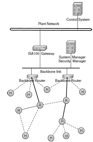
Figure 7.2 Forwarding at the link-layer through the ISA100 protocol stack.
7.1.4 ISA100.11a data link layer
As mentioned, the ISA100.11a DLL provides support for the creation, maintenance and packet forwarding functions required for the wireless sensors. In the OSI model the DLL sits between the physicallayer and the network layer. It establishes data packet structure, framing, error detection and bus arbitration. The DLL also includes the medium access control (MAC) functions. In ISA100.11a the DLL was extended to include the following functions:
- link-local addressing for PAN entities
- message forwarding from one PAN node to another
- PHY management
- adaptive channel hopping
- message addressing, timing and integrity checks
- detection and recovery of message loss
Messages are communicated in discrete 10–12 millisecond time-synchronized slots. This time synchronization provides extremely accurate time stamping, and the adaptive channel hopping increases reliability by avoiding occupied or noisy channels. In addition, the timesynchronized slots and channel hopping reduce the utilization of any single channel thereby improving ISA100.11a’s coexistence with other RF networks in the same spectrum.
The DLL creates and uses a tree-like routing algorithm called graphs. The concept of graph routing provides for a number of different data paths for different types of network traffic within the DL subnet. The multiple graphs are used by different nodes to transmit different types of data. For example, a node will use one graph route to send intermittent sensor data to the plant network and will use another graph route to send bulk series data. While all of the roots of the graphs are generally anchored at the same point, within the DL subnet, the path of the messages from any single node may vary greatly depending on the traffic type, bandwidth required and other factors. These various graphs are created by the network management system (NMS).
The NMS takes input from the system/network designer as to the specific requirements for data throughput and transmissions, and information provided by the sensor nodes about the RF environment. Based on this the NMS calculates and creates a set of graphs, and assigns contract IDs to the graphs. The applications on the sensor nodes then use these contract IDs to notify the nodes on the route to the plant network as to the requirements for the transmission and forwardingof that particular message. The graphsare instantiated based on specific traffic characteristics. The ISA100.11a committee defined four traffic types:
Periodic data: Data that is published periodically and has a well-understood data bandwidth requirement, both deterministic and predictable. Timely delivery of such data is often the core function of a wireless sensor network, and permanent resources are assigned to ensure that the required bandwidth stays available. Buffered data usually exhibits a short Time to Live, and the newer reading obsoletes the previous one. In some cases, alarms are low priority information that get repeated over and over. The end-to-end latency of this data is not as important as the regularity with which the data is presented to the plant application.
Event data: This category includes alarms and aperiodic data reports with bursty data bandwidth requirements. In certain cases, alarms are critical and require a priority service from the network.
Client/server: Many industrial applications are based on a client/server model and implement a command-response protocol. The data bandwidth required is often bursty. The acceptable round-trip latency for some legacy systems was based on the time to send tens of bytes over a 1200 bit/s link (hundreds of milliseconds is typical). This type of request is statistically multiplexed over the network and best-effort service is usually expected.
Bulk transfer: Bulk transfers involve the transmission of blocks of data in multiple packets where transient resources are assigned for a limited period of time (related to file size and data rate) to meet the bulk transfer’s service requirements, such as a transaction time constraint.
The NMS uses these different traffic types along with the requirements for the amount of data, frequency and latency requirements to calculate primary and backup graphs for the specific traffic. The NMS also takes into account the performance of the various channelsbetween pairs of nodes as well as the power constraints of each node that the traffic will pass through. At the end of the calculations contract IDs are assigned to each of the graphs. These contract IDs are carried within the DLL header, and each node on the forwarding tree examines the contract ID to determine the “next hop” for the message.
In this way the ISA100.11a DLL provides a robust and flexible network topology upon which to build higher layer network functionality. It supports low-power and highavailability operations even in the presence of non-intentional interferers and it supports data transmission characteristics for the different types of network traffic required in an industrial process control or factory automation application.
7.2 Wireless RFID Infrastructure
A system for deploying RFID reader infrastructures for identification and access control using wireless 6LoWPAN technology has been developed by Idesco and Sensinode. Idesco is a Finnish manufacturer of identification systems, and was the first company in the world specialized in RFID [Idesco]. Idesco offers scalable open identification solutions enabling new business opportunities for forerunners in the field. This new wireless system is called the Idesco Cardea system, consisting of a line of wireless RFID products including:
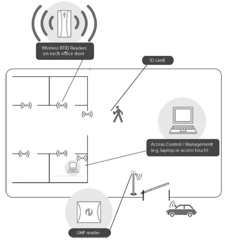
Figure 7.3 The Idesco Cardea system architecture. (Reproduced by Permission of © Idesco Oy.)
- Idesco Cardea readers
- Idesco Cardea door control unit
- Idesco Cardea control unit and access touch
The system uses Sensinode wireless networking technology, based on 2.4 GHz IEEE 802.15.4 and 6LoWPAN standards. Traditional RFID tags are read at short range using the RFID Cardea reader products. Instead of using wired cabling between all of the RFID infrastructure components, the Cardea system uses a wireless 6LoWPAN mesh network to interconnect the devices. The system is illustrated in Figure 7.3. A typical system consists of RFID readers, door control units and a controller unit. The Cardea system includes both a Cardea controller unit accessible through PC software, or the Cardea access touch, which is a wall-integrated touch-screen device.
Traditional RFID infrastructures rely heavily on cabling between all components in the system and the use of legacy centralized controller units. Cabling is typically realized in these systems using RS-485, Wiegand connections or, more recently, IP-based Ethernet cabling. The Wiegand protocol (named after the Wiegand effect) is commonly used for connecting card readers with electronic entry systems over three-wire cables. The installation of cabling,especially in existing and historical buildings, is a painstaking and expensive investment. The use of legacy cabling has also resulted in the centralized control of these systems with specialized legacy controllers. The combination of cabling and legacy infrastructure makes RFID systems expensive, and limits the use of RFID in many applications. By using a lowpower wireless mesh network, several benefits were achieved with the Idesco Cardea system:
- The Idesco Cardea system takes just an estimated 40 minutes to install per door, compared to an average of 7 hours per door for a traditional wired RFID infrastructure.
- Significant cost savings in cabling for retrofitting the system in existing buildings, or for modification of a system in a current installation.
- The possibility of using RFID solutions as part of temporary installations.
- RFID becomes practical and cost-effective for small office installations.
- The ability to easily combine existing wired and Cardea wireless components.
Typical applications of the Cardea systems include:
- small installations with a few doors and a few readers (such as small offices or shops)
- temporary access systems, e.g. at construction sites or events
- systems where multiple applications need to be combined together (e.g. access control and parking lot access)
- applications with readers spread across large areas, such as harbors
- installations in existing and especially historic buildings
- easy expansion of existing systems without adding more cabling
7.2.1 Technical overview
The system is realized using Sensinode’s NanoStack 2.0 6LoWPAN solution, providing communication between the wireless components in the system as shown in Figure 7.4. Making use of IEEE 802.15.4 2.4 GHz radios with power amplification, suitable range is achieved. Furthermore, multihop routing using Sensinode’s NanoMesh is used to extend the network over larger areas. Security is achieved with 128-bit AES link-layer encryption combined with application protocol security already used in wired systems. Devices in the network use unique 64-bit MAC addresses so that all devices have a unique IPv6 address. In the future, battery-powered wireless RFID readers will be added to the cardea system. These run as LoWPAN hosts with aggressive power savings for long battery life. All powered devices, including RFID readers and door controller units act as LoWPAN Routers. The controller units in the network act as LoWPAN Edge Routers. The network achievescomplete autoconfiguration, which makes the setup of the system using a graphical interface easy. Installation of the system doesn’t require special knowledge of IPv6 networking or wireless communications, and can be performed by existing installation personnel. The use of IPv6 end-to-end will enable the evolution of the Cardea system into larger-scale access control applications and integration with other building automation systems.
Figure 7.4 The wireless communications between Cardea components. (Reproduced by Permission of © Idesco Oy.)

7.2.2 Benefits from 6LoWPAN
6LoWPAN technology has enabled Idesco to continue its leading developments in the RFID field. The resulting Idesco Cardea system is unique in the world. “Idesco sees a great market potential for wireless Cardea products. 6LoWPAN technology, which is designed for transferring small data amounts over short distances, is ideal for applications using RFID for identification. The unique identification number (UID) is typically the only data that needs to be transferred from the RFID reader to the upper levels in the system. As the network routes itself automatically and no cables are required, the installations can be done in a more flexible and cost-efficient manner.” says Anu-Leena Arola (Director, R&D and Services) for Idesco.
7.3 Building Energy Savings and Management
The LessTricity system has been developed by a consortium of companies in the UK, for the purpose of increasing the efficiency of energy usage and better management in commercial buildings and businesses. The consortium includes companies involved in commercial property management (MEPC), building design, engineering and management (WSP Group), electronic product design and manufacturing (GSPK Design Ltd), management software design and implementation (TWI) and low-power wireless networking (Jennic Ltd). The project has received additional funding from the UK government’s Technology Strategy Board whose mission is to promote and support research, development and exploitation of technology and innovation for the benefit of businesses in the UK.
The aim of the LessTricity consortium was to develop a centralized management systemto help eliminate the wasteful use of electrical power by appliances in buildings. The system uses wireless control and measurement technology based on 6LoWPAN to enable the management of large facilities and even remote buildings. It can be easily installed in both new and existing buildings, is transparent to users, offers advanced metering features and has low operating costs. Such a system can also be integrated into a larger facility management system, such as that introduced in Section 1.1.5.
LessTricity technology is initially aimed at industrial, commercial and public service market segments, which make up almost 52 percent of electricity consumption in the UK. A report in 2004 from the UK Department of Environment, Food and Rural Affairs showedthat UK businesses wasted 30 percent of energy purchased and, for many, a 20 percent cut in energy costs would represent a benefit equivalent to a 5 percent increase in revenue given rising energy costs [DEFRA].
7.3.1 Network architecture
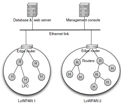
The network architecture of the LessTricity system is shown in Figure 7.5. A typical small deployment consists of clusters of about 50 LessTricity power controllers (LPCs) into which appliances to be measured are plugged. Each LPC monitors the amount of power being consumed and transmits this through a multihop 6LoWPAN network to a LessTricity network interface (LNI). The LNI acts as a LoWPAN Edge Router between the LoWPAN and the Ethernet network. Power readings from LPCs are sent to a central database where they are stored. Standardized reports on aggregate and individual appliance energy use can be produced using SQL queries, to allow building owners to analyze their energy consumption. A graphical web interface is also provided for both monitoring and managing energy consumption in the LPCs and to manage the network and LPCs themselves.
7.3.2 Technical overview
The LPCs consist of an enclosure containing a standard UK 13 A socket into which the appliance is plugged, and a lead terminating in a 13 A 3-pin plug for connection into the mains power supply. The device is able to measure instantaneous current and voltage on the socket, attached to a wireless microcontroller module supplied by Jennic.
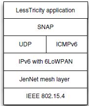
The LPCs communicate back to the wireless infrastructure of the building using the transmitter of the JN5139 system-on-a-chip radio. This single-chip device contains a 32bit processor along with peripherals and an IEEE 802.15.4 2.4 GHz radio. Thus this device has been implemented using the single-chip stack model described in Section 6.1.1. The protocol stack running on the LPCs and LNI is illustrated in Figure 7.6. Multihop networkingis provided by Jennic’s JenNet self-healing Mesh-Under technique over the IEEE 802.15.4 MAC. Thus this can be considered to be a proprietary link-layer mesh technique. A LoWPAN adaptation layer compliant with [RFC4944] is implemented under IPv6, along with UDP and ICMPv6 implementations. Any LPC is capable of acting as a router for packets from any other device. Jennic’s simple network access protocol (SNAP), covered in Section 6.2.4, is used as an application protocol for the LessTricity application running on the nodes.
Figure 7.5 The typical network architecture of a LessTricity deployment.
The LNI is based around Jennic’s Ethernet border router consisting of a higher performance microcontroller with an Ethernet interface along with a JN5139 wireless module, which are interconnected by a high-speed serial interface. This configuration follows the network processor setup for edge routers described in Section 6.4. An IPv6 protocol stack on the Ethernet microcontroller handles networking on the Ethernet side and routes packets between the two interfaces. The JN5139 handles 6LoWPAN networking and acts like a network interface under the IPv6 stack.
7.3.3 Benefits from 6LoWPAN
By using a 6LoWPAN based approach, the system could be easily deployed in a building using the low-power IEEE 802.15.4 wireless network, while at the same time connect into the building’s existing IT infrastructure thanks to the use of standard Internet protocols. Theenergy usage information can then simply be made available locally or over the Internet for remote monitoring, e.g. for corporate energy usage monitoring. The end-user focus is on reducing the energy footprint of their operations, both from a cost savings and an environmental responsibility point of view. “We have found it a great advantage to be able to add Ethernet connectivity to a wireless network and with it the possibility of Internet access to any node simply by utilizing existing IP-based standards. Coupled with the SNAP layer, it has enabled several different applications to be written and deployed for Internet use in veryshort timescales,” says Paul Chilton of Jennic.
Figure 7.6 The Jennic 6LoWPAN stack with the LessTricity application.
The LessTricity system has gone through field trials in 2009 in business facilities around the UK. These field trials were used to establish a base energy usage statistics for the trial sites, which can be compared to their energy usage after the management features of the system are taken into use