

i
i
i
i
i
i
i
i
512 18. Building on the Basics, Some Projects in VR
We can put together a program to produce the chroma-key effect using a
webcam and an AVI movie. DirectShow provides all the software components
needed, and we’ve covered most of the other detail in Chapter 15 already. It is
simply a matter of building a suitable FilterGraph. If you have two webcams,
you can even do it in stereo. We will base most of our application on the code
from Section 15.4 concerning live video capture into an OpenGL texture.
The program has three threads of execution:
1. A thread to run the parent window and the control panel dialog box.
2. A thread to run the camera video capture FilterGraph (the output is
written to an intermediate memory buffer) and OpenGL (OGL) tex-
ture renderer . The OGL renderer paints the texture from the interme-
diate buffer onto a mesh rectangle that has been scaled to exactly fill
a child window of the application. Before rendering the texture, the
chroma-key effect is generated by mixing the video frame data in the
memory buffer with the movie frame data obtained in the third thread.
3. A thread to run a FilterGraph which plays an AVI movie file using our
custom renderer from Chapter 15. The custom renderer filter sends
the movie frame images to a second memory buffer.
The structure of the application’s FilterGraph is illustrated in Figure 18.4,
and the chroma-key effect is demonstrated in Figure 18.5. The important
code that carries out the mixing is in the
CopyMediaSample(..) function.
It operates on the red, green and blue color components and uses some user-
defined thresholds to define at what levels the chroma-key kicks in.
Figure 18.4. The FilterGraph for the chroma-key project. The video RAM buffer
content is combined with the AVI movie buffer content by chroma-keying on a blue
or green key color in the video buffer.

i
i
i
i
i
i
i
i
18.4. Chroma-Keying 513
Figure 18.5. Chroma-key in action. At the top left is a frame from a movie. The
dialog below sets the color thresholds. At (a), the camera image shows a desktop (a
yellow ball sits in front of a screen showing a green color). When the chroma-key
is turned on, at (b), parts of the green screen that are visible are replaced with the
frames from the AVI movie.
Generating a chroma-key effect using a blue or green background is not
the only way one might achieve a similar result. An alternative (and one you
might care to try for yourselves) is to key on differences. The idea behind
keying on differences is:
Set u p the webcam, take a photo of the background (no need for
a constant color) and store this background. Now let someone or
something move into the scene. By comparing the pixel colors
from the captured photo with the color from the new scene,
we can determine whether a value is part of the background or
not. When operating in chroma-key mode, the program replaces
anything it thinks belonged to part of the original background
with the material we wish to key in as the new background.
Another possible alternative is to key on a color specified by its hue, sat-
uration and value (HSV). The HSV model provides a more natural way to
select color, and it may be easier to choose a key color using this model than
with the RGB components. Or, the application could offer a color picker fa-
cility where the user points to a pix el in the scene and that color (or a close
variant of it) is chosen as the key color.
In practice, of course, few things work exactly as one would expect. Un-
less the lighting conditions are good (almost up to studio conditions), the
cameras have adequate color performance and the background color is highly
monochromatic, it can be very difficult to get the key color to match the
background as we would wish.
i
i
i
i
i
i
i
i
514 18. Building on the Basics, Some Projects in VR
18.5 A Multi-Projector VR Theater System
In Chapter 4, we discussed building a basic immersive VR environment by
projecting overlapping images, movies and real-time interactive 3D content
onto curved surfaces. A design based on two projectors can be driven by one
PC system, because most graphics adapters have two video outputs on which
one can display different parts of the desktop.
2
The project described in this section offers a simple solution for the case
where we need to drive a four-projector set-up such as that illustrated in Fig-
ure 4.13. The controlling software provides a collection of programs to cor-
rect for the distortions that arise when a conventional projector system throws
its output onto a cylindrical screen, as in Figure 4.11. The project will also
offer some code and suggestions for how to link and control two PCs using
an Ethernet network so that the four outputs can be generated by using two
stereo-ready graphics adapters, without any requirement for special-purpose
hardware.
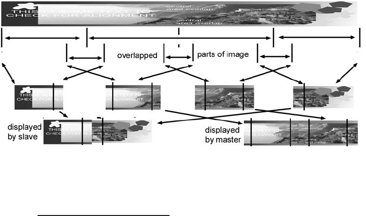
The basic idea underlying the project is to divide the image or movie into
four sections. The two central sections are displayed by a master computer,
Figure 18.6. Dividing up an image for display in four pieces. Overlaps are used so that
the projected pieces can be blended. The master machine drives the two projector s
displaying the central area. The slave machine drives the two projectors showing the
extreme left and extreme right image segments.
2
We will do this by setting up one wide desktop, rendering the output to go to one of the
projectors from the left side of the desktop and the output for the other projector from the
righthalfofthedesktop.
i
i
i
i
i
i
i
i
18.5. A Multi-Projector VR Theater System 515
and the two peripheral sections are displayed by a slave computer under the
remote control of the master. This arrangement is described in Figure 18.6.
As we have noted before, it is necessary to arrange some overlap between the
images. This complication necessitates sending more than one half of the
image to each of the two pairs of projectors.
We don’t have space here to go into a line-by-line discussion of how the
code works. As you might guess, however, we have already encountered most
of the coding concepts we need to use
3
in previous chapters. It is now only
a matter of bringing it together and adapting the code we need. By knowing
the overall design of the project software, you should be able to follow the
fine detail from the documentation on the CD and comments in the code.
18.5.1 Hardware and Software Design
Sincewearegoingtobedrivingfourprojectors,wewillneedtwoPCs,each
with a dual-output graphics adapter. The PCs will be connected together
through their Ethernet [2] interfaces. YoucanjointhePCsinback-to-back
fashion or use a switch/hub or any other network route. In our program, we
assume that the PCs are part of a private network and have designated private
IP addresses [5] of 192.168.1.1 and 192.168.1.2. The two machines will
operate in a client-server model with one of them designated the server and
the other the client. On the server machine, a program termed the master will
execute continuously, and on the client machine another program termed the
slave will do the work. It is the job of the master program to load the images
(or movies), display their central portion and serve the peripheral part out to
the slave. It is the job of the slave to acquire the peripheral part of the image
(or movie) from the master and display it
4
.
Whilst the same principles apply to presenting images, movies or interac-
tive 3D content across the multi-projector panorama, we will first discuss the
display of wide-screen stereoscopic images. The software design is given in
block outline in Figure 18.7. In Section 18.5.3, we will comment on how the
same principles may be used to present panoramic movies and 3D graphics.
3
Actually, we have not discussed Windo ws sockets and TCP/IP programming before but
will indicate the basic principles in this section.
4
Wedon’twanttocomplicatetheissuehere,butontheCDyouwillfindacoupleofother
utilities that let us control both the master and the slave program remotely over the Internet.
You will also see that the architecture of the master program is such that it can be configured
to farm out the display to two slave programs on different client machines. It could even be
easily adapted to serve out the display among four, e ight or more machines.

i
i
i
i
i
i
i
i
516 18. Building on the Basics, Some Projects in VR
Figure 18.7. A block outline of the software design for the master/slave quad-projector
display. The steps labeled 1 to 5 illustrate the sequence of events which occur when
an image (or sequences of images are displayed.)
The logical execution of the system proceeds as follows:
• Master and slave applications both enter window message-processing
loops and await commands. The master application starts two ad-
ditional communications threads (using Windows sockets) to handle
communications. One thread will handle requests from the slave to
..................Content has been hidden....................
You can't read the all page of ebook, please click here login for view all page.