

i
i
i
i
i
i
i
i
522 18. Building on the Basics, Some Projects in VR
Figure 18.9. Placing miniature mesh figures onto a real desktop illustrates the capabil-
ity of an AR head-mounted display.
18.7.1 The ARToolKit
At the core of the ARToolKit is the action of placing the 3D object into the
field of view of a camera so that it looks as if the object were a ttached to a
marker in the real world. This is best illustrated with an example. F irst we
see the scene with the square marker indicated on the white sheet of paper in
Figure 18.10(a).
The software in the ARToolKit produces a transformation matrix that,
when applied to an OpenGL scene, makes it look as if the object were cen-
tered on the marker and lying in the plane of the marker. (The marker is
actually a black outline with the word “Hiro” inside; this detail is not clear
in Figures 18.9 and 18.10). The nonsymmetric text in the marker allows a
definite frame of reference to be determined. When we render an OpenGL
mesh, it will appear to sit on top of the marker (see Figure 18.10(b)). If we
move the piece of paper with the marker around (and/or move the camera)
then the model will appear to follow the marker, as in Figure 18.10(c).

i
i
i
i
i
i
i
i
18.7. Augmented Reality (AR) 523
Figure 18.10. In the ARToolKit, a marker in the camera’s field of view (a) is used to
define a plane in the real world on which we can place a synthetic object so that it
looks like it is resting on the marker (b). Moving the marker causes the object to
follow it and so gives the illusion that the synthetic object is a ctually resting on the
marker.
In the examples shown, the 3D mesh model is centered 50 m m
above the center of the marker so the marker itself is partially visible and the
object appears to hover over it. As the marker is moved, the object moves with
it. If the marker is moved away from the camera, it gets smaller and so does
the object. The ARToolKit software has a lot of clever work to do in order
to make this simple looking thing possible. Fortunately, in practice, it is
quite easy to use the ARToolKit provided one understands the coordinate
systems.
In Figure 18.11, all the coordinate systems in use are shown. The AR-
ToolKit uses two coordinate frames of reference, one based at the camera cen-
ter (ARC) and one based at the marker center (ARM). OpenGL is used for
rendering, and so all 3D mesh drawings take place in their own frame of ref-
erence (OGL). The marker’s coordinates coincide exactly with the OpenGL
coordinate system, so to draw something normal to the plane of the marker,
one increases the z-coordinate in OpenGL. The modeling software (OpenFX
or 3DStudio) use a mathematical coordinate system where z is considered
vertical as opposed to OGL’s, in which the y-coordinate is vertical. So, when
rendering a mesh model, one must remember to swap the z-value to y and
the y-value to −z. This important property, and a reminder of the coordinate
systems we need to use, is depicted in Figure 18.11.
Because the AR marker and OpenGL coordinate systems are the same, all
one has to do to render a 3D mesh model so that it looks as if it is stuck to
the marker is draw its polygons using OpenGL coordinates. So, for example,
to render a line running vertically for 10 units from the center of the maker
relative to the plane of the maker, one uses the OpenGL library function calls:

i
i
i
i
i
i
i
i
524 18. Building on the Basics, Some Projects in VR
glBegin(GL_LINES);
glVertex3f(0.0,0.0, 0.0);
glVertex3f(0.0,0.0,10.0);
glEnd();
Note: to obtain an orientation, such as that depicted for the plane in
Figure 18.10, when we are loading the mesh from an OFX or 3DS file, we
must perform an additional rotation of 90 degrees about the x-axis. This is
because if we just carried out the swap of coordinates as indicated above (z to
y etc.) the model (of the plane etc.) would appear to point down—towards
the marker.
Figure 18.11. Coordinate frames of reference used in the ARToolKit and the 3D
modeling software packages.
18.7.2 How the ARToolKit Works
As we discussed in Chapter 8, the transformation (the homography) that
maps a plane in which the marker lies (and with it the marker’s coordinate
frame of reference) must be obtained by identifying at least the four points at
the corners of the marker and in their correct order. Once these points have
been identified, the transformation from camera frame of reference to marker
frame of reference may be determined. Since the camera’s frame of reference
is considered the global frame of reference, any 3D model can be made to

i
i
i
i
i
i
i
i
18.7. Augmented Reality (AR) 525
behave as if it were lying in the marker’s frame of reference by applying the
transformation to it.
In the examples covered in Chapter 8, identification of the points around
the square marker was done manually. In the ARToolKit, this process is auto-
mated by carrying out an automatic pattern recognition to identify the four
corners of the marker. However, before t his can be done, the camera must be
calibrated. Calibration of the camera is necessary to determine any distortion
in the lens as well as the field of view and aspect ratio. The camera parameters
are stored in a file “data/camera
para.dat” in the example code. Correcting for
distortion is necessary because it helps in the recognition of the marker. By
knowing the field of view, aspect ratio and the marker ’s real-world size, one
can also get an approximate value for the distance it is away from camera.
The process of r ecognizing the marker and hence determining its corner
positions in the 2D camera’s image requires some knowledge of the pattern in
the marker. This information is stored in a file; for the basic ARToolKit pat-
tern, this file is “data/patt.hiro”.
7
The process of recognition is only explained
briefly in the ARToolKit documentation, but it suggests that there are several
stages. These are:
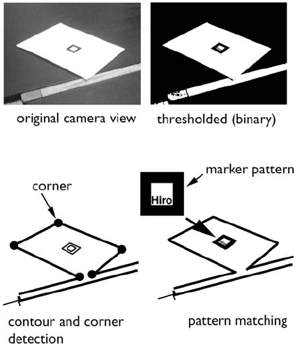
1. Turn the image into a binary bitmap, i.e., every pixel is represented by
a binary state—black or white. A threshold intensity level is set. Above
this threshold the pixel value is 1; below it the pixel value is 0.
2. Using the binary image, the ARToolKit attempts to identify a set of
lines in the image. (Some of these will hopefully be identified as the
edges round the m arker.)
3. Try to find the places where these lines meet to form the corners of the
possible image of the marker.
4. Read the pattern from the marker’s pattern file and, using it as a tem-
plate, attempt to match it to the region bounded by the possible corners
and edges of the putative marker.
5. When a match is detected with some degree of confidence, the homog-
raphy that maps the marker’s and camera’s frames of reference may be
determined by using an equation analogous to Equation (8.4).
7
It is possible to build this pattern information for other “custom” markers; you should
consult the ARToolKit documentation for details on how to do this. It is also possible to
instruct the ARToolKit to look for several different markers in the same image; again, consult
the documentation for information on how to do this.
i
i
i
i
i
i
i
i
526 18. Building on the Basics, Some Projects in VR
Figure 18.12. The steps performed by the AR ToolKit as it tracks a marker in the
camera’s field of view and determines the mapping homology between the plane in
which the marker lies and the camera’s projection plane.
This process is illustrated in Figure 18.12, where the matched rectangle
contains the four corner locations that can be used to determined the trans-
formation from the camera to marker frames of reference.
Full implementation details can be found from following the comments
in the code and the project’s commentary on the CD.
18.8 Virtual Sculpting in 3D
To finish off this chapter, we thought we’d put together a small project for a
desktop VR system that brings together some of the concepts we have been
developing in the last few chapters. Actually, it is quite a large project It is a
desktop program that brings together input from two joysticks that will con-
trol a couple of virtual tools that we can use to push and pull a 3D polygonal
mesh in order to sculpt it into different shapes. The display will be stereoscop-
..................Content has been hidden....................
You can't read the all page of ebook, please click here login for view all page.