
i
i
i
i
i
i
i
i
6.6. Transformations 139
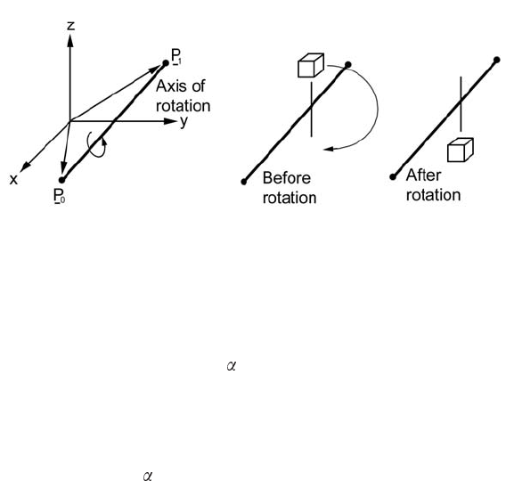
Figure 6.14. Rotation round an arbitrar y vector.
been obtained representing the composite transformations, it can be used in
the same way as any other transformation matrix.)
The following outlines an algorithm to construct a transformation matrix
to generate a rotation by an angle
around a vector in the direction P
1
−P
0
:
1. Translate P
0
to the origin of coordinates
2. Align rotation axis P
1
− P
0
with the x-axis.
3. Rotate by angle
round x-axis.
4. Make inverse transformation to undo the rotations of Step 2.
5. Translate origin of coordinates back to P
0
to undo the translation of
Step 1.
The full algorithm is given in Figure 6.15.
6.6.6 Viewing Transformation
Before rendering any view of a 3D scene, one has to decide from where to
view/photograph the scene and in which direction to look (point the cam-
era). This is like setting up a camera to take a picture. Once the camera is
set, we just click the shutter. The camera projects the image as seen in the
viewfinder onto the photographic film and the image is rendered. Likewise,
when rendering a 3D scene, we must set up a viewpoint and a direction of
view. Then we must set up the projection (i.e., determine what we can and
cannot see), which is discussed in Section 6.6.7.
In mathematical terms, we need to construct a suitable transformation
that will allow us to choose a viewpoint (place to set up the camera) and

i
i
i
i
i
i
i
i
140 6. A Pocket 3D Theory Reference
Let d = P
1
− P
0
T
1
= a translation by −P
0
d
xy
= d
2
x
+ d
2
y
if d
xy
< ε { rotation axis is in the z-direction
if d
z
> 0makeT
2
a rotation about z by α
else T
2
= a rotation about z by −α
T
3
= a translation by P
0
return the product T
3
T
2
T
1
}
d
xy
=
d
xy
if d
x
= 0andd
y
> 0 φ = π/2
else if d
x
= 0andd
y
< 0 φ = −π /2
else φ = ATAN 2(d
y
, d
x
)
θ = ATAN 2(d
z
, d
xy
)
T
2
= a rotation about z by −φ
T
3
= a rotation about y by − θ
T
4
= a rotation about x by α
T
5
= a rotation about y by θ
T
6
= a rotation about z by φ
T
7
= a translation by P
0
Multiply the transformation matrices to give the final result
T = T
7
T
6
T
5
T
4
T
3
T
2
T
1
Figure 6.15. Algorithm for rotation round an arbitrary axis. Points d
x
, d
y
and d
z
are
the components of vector d.
direction of view (direction in which to point the camera). Once we have this
view transformation, it can be combined with any other transformations that
needs to be applied to the scene, or to objects in the scene.
We have already seen how to construct transformation matrices that move
or rotate points in a scene. In the same way that basic transformation matrices
were combined in Section 6.6.5 to create an arbitrary rotation, we can build
a single matrix, T
o
, that will transform all the points (v ertices) in a scene in
such a way that the projection of an image becomes a simple standard process.
But here is the funny thing. In computer graphics, we do not actually change
the position of the camera; we actually transform or change the position of
all the vertices making up the scene so that camera is fixed at the center of the
universe (0, 0, 0) and locked off to point in the direction (1, 0, 0) (along the
x-axis).

i
i
i
i
i
i
i
i
6.6. Transformations 141
There is nothing special about the direction (1, 0, 0). We could equally
well have chosen to fix the camera to look in the direction (0, 1, 0), the y-
axis, or even (0, 0, 1), the z axis. But we have chosen to let z represent the
up direction, and it is not a good idea to look directly up, so (0, 0, 1) would
be a poor choice for viewing. (Note: The OpenGL and Direct3D software
libraries for 3D graphics have their z-axis parallel to the viewing direction.)
Once T
o
has been determined, it is applied to all objects in the scene. If
necessary, T
o
can be combined with other transformation matrices to give a
single composite transformation T .
Figure 6.16. Viewpoint and direction of view.
A viewing transformation depends on:
• Position of the viewpoint (camera location). (A vector p
o
.SeeFig-
ure 6.16.)
• The direction in which we wish to look: north, south, east or west.
This is measured by an angle
which is relative to the x-axis and lies in
the xy -plane. is positive to the right of the x-axis when looking along
x from the viewpoint.
• The amount by which we look up or down. The angle
measures this
relative to the xy -plane. It is positive when looking down. Note that
when determining a viewing transformation, the effect of looking up
or down comes into play after the direction of view has been accounted
for, and therefore it is equivalent to a rotation around the y-axis.
• The degree to which our head is tilted to the left or right. This is
measured by the angle
. To be consistent with the right-handed frame

i
i
i
i
i
i
i
i
142 6. A Pocket 3D Theory Reference
of reference and sense of rotation, is positiv e when the camera tilts to
the right as it looks from p
o
along the x-axis.
A viewing transformation appears to operate in reverse to ordinary trans-
formations. For example, if you tilt your head to the left, the world appears
to tilt to the right. Note carefully that the angle
is positive if we are looking
down and negative if we looking up. If you prefer, you can think of as the
heading, as the pitch and as the degree of banking.
The viewing transformations are also combined in the reverse order to the
order in which a transformation is assembled for objects placed in a scene. In
that case, the rotation around the x-axis is applied first and the translation by
p
o
is applied last.
Given the parameters p
o
, , and (illustrated in Figure 6.16), the
transformation T
o
is constructed by the following algorithm:
Place observer at (0, 0, 0) with the transformation:
T
1
= a translation by −p
o
Rotate the direction of observation into the xz-plane with:
T
2
= arotationaboutz by −
Align the direction of observation to the x-axis with:
T
3
= arotationabouty by −
Straighten the camera up with transformation:
T
4
= arotationaboutx by −
Multiply the individual transformation matrices to give
one composite matrix representing the viewing transformation:
T
0
= T
4
T
3
T
2
T
1
6.6.7 Projection Transformation
After we set up a camera to record an image, the view must then be projected
onto film or an electronic sensing device. In the conventional camera, this is
done with a lens a rrangement or simply a pinhole. One could also imagine
holding a sheet of glass in front of the viewer and then having her trace on
it what she sees as she looks through it. What is drawn on the glass is what
we would like the computer to produce: a 2D picture of the scene. It’s even
shown the right way up, as in Figure 6.17.
i
i
i
i
i
i
i
i
6.6. Transformations 143
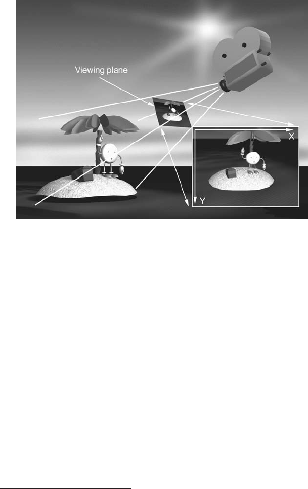
Figure 6.17. Project the scene onto the viewing plane. The resulting two-dimensional
image is then recorded or displayed.
It is straightforward to formulate expressions needed to perform this (non-
linear) transformation. A little thought must be given to dealing with cases
where parts of the scene go behind the viewer or are partly in and partly out
of the field of view. The field of view (illustrated in Figure 6.18) governs how
much of the scene you see. It can be changed so that you are able to see more
or less of the scene. In photography, telephoto and fish-eye lenses have differ-
ent fields of view. For example, the common 50 mm lens has a field of view
of 45.9
◦
. Because of its shape as a truncated pyramid with a regular base, the
volume enclosed by the field of view is known as a frustum.
One thing we can do with a projective transformation is adjust the aspect
ratio.Theaspect ratio is the ratio of height to width of the rendered image.
It is 4 : 3 for television work and 16 : 9 for basic cine film. The aspect ratio
is related to the vertical and horizontal resolution of the recorded image. Get
this relationship wrong and your spheres will look egg shaped.
Before formulating expressions to represent the projection, we need to
define the coordinate system in use for the projection plane. It has become
almost universal
3
to represent the computer display as a pair of integers in
3
However, there are important exceptions, e.g., the OpenGL 3D library, where floating-
point numbers are used.
..................Content has been hidden....................
You can't read the all page of ebook, please click here login for view all page.