
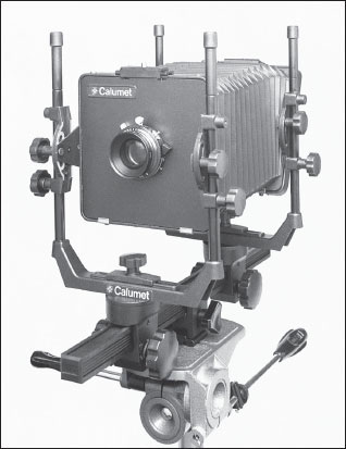
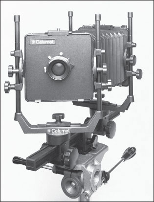
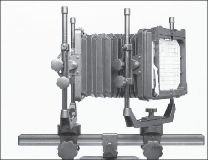
Now that you are familiar with the structure of your camera, you can begin to put it to use. Establishing a familiar pattern of use with your camera will enable you to set it up and adjust it while concentrating on the image you wish to make. Initially, setting up the camera will demand your undivided attention, so before you take it out into traffic, practice setting up and adjusting your camera in a place where you can work comfortably and without distraction.
This section is designed to get you working with your camera as soon as possible. First we will move through the making of a simple exposure and the sequence of actions you must follow for every photograph. Using the camera this way will be very much like using a bigger version of a camera you already know and you will soon become comfortable with the essentials of view camera use. The latter part of the chapter will introduce you to the way the camera movements influence and control perspective and focus. Mastering the camera movements is difficult and should be left until you are comfortable with the basics of using the camera.
Many of the camera parts and accessories mentioned here are explained in detail later, so you can read through this sequence of steps rapidly, without digression. For more complete information, refer to the page numbers indicated.
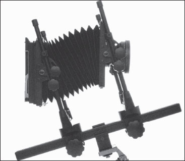
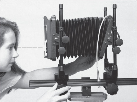
Before mounting the camera on your tripod (p. 136), extend the tripod’s legs so that its platform is at chest height. This positioning places the tripod’s feet far apart to give you a steady platform for attaching the camera. It also places the ground-glass viewing screen at a comfortable height just below eye level. Save lower camera positions for a time when you are proficient and can set up and work quickly—prolonged viewing in low positions can strain your lower back. After a little experience, you will know in advance how much to extend the tripod’s legs for the vantage point you desire. Remember that the height of the platform is much easier to adjust before you have the weight of the camera on it.
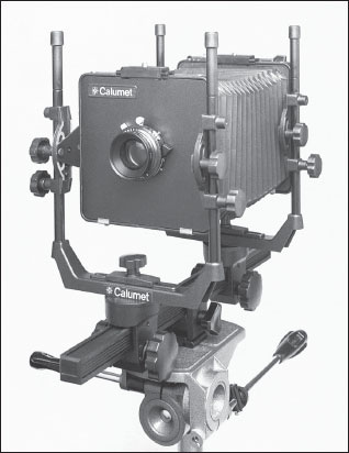
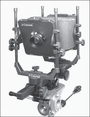
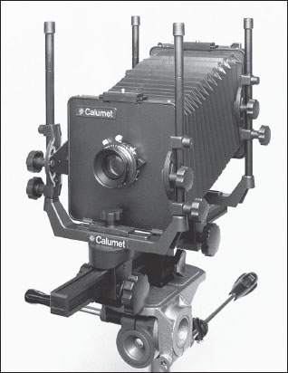
Locate the threaded mounting bolt projecting through the platform of your tripod head (p. 138) and the corresponding threaded hole in your camera’s rail clamp or baseplate. With one hand hold the camera as close to its top as possible while aligning and threading the mounting screw into the hole in the baseplate with your other hand. Make sure the rail, or lens axis, is aligned with the axis of the tripod head before you tighten the mounting screw securely. Many cameras have a carrying handle at the top of the rear standard, which makes the mounting operation much easier. Never hold a view camera in one hand by its monorail—this is an invitation for the camera to invert and crash into the tripod or, worse, onto the ground.
Before you release your grip on the camera and rely upon the tripod for safe support, be sure all the adjustment levers on the tripod head are secure. If just one lever works loose, the camera may tip and capsize the entire tripod. Check also to make sure the lens and lensboard are securely attached before you move or tilt the camera. The most convenient way to move the camera more than a few steps is to lean it over your shoulder, but this rifle-carry position places considerable strain on the mount. If the camera comes loose, a fall from shoulder height could irreparably damage both camera and lens.
Swivel the tripod head to align the axis of the monorail and lens with one leg of the tripod. This position, with one tripod leg pointed forward, will give you room to move around behind the camera between the other two legs without continually kicking or tripping over one tripod leg. It will also provide a more stable platform should you tilt the camera downward.
It is not practical to take frequent casual glances through a view camera—the way you might with a 35mm—to decide on the correct camera position for the image you desire. Instead you will need to train your eye to see what the camera sees. With time you will be able to place the tripod in its final position the first time you set it down. For now, place the tripod approximately and point the camera in the general direction for the photograph you plan to make.
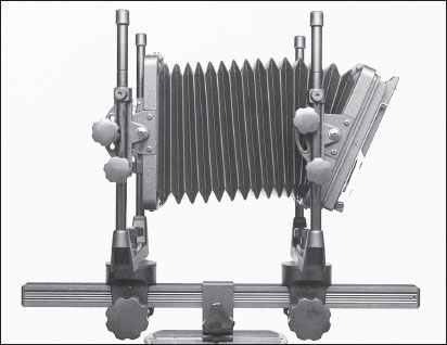
Zero Position
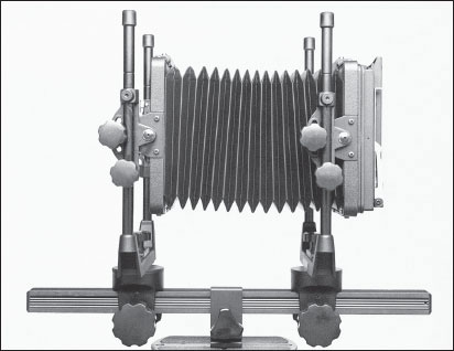
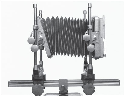
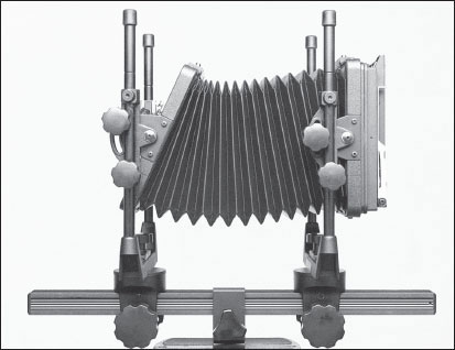
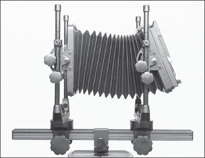
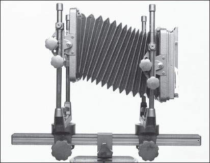
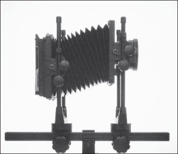
Zero position for a view camera means that all of its adjustments are set as though it were a rigid-bodied camera: front and rear standards are parallel to one another and at right angles to the monorail and the rear of the lens is pointed straight at the center of the ground glass. This neutral setting is sometimes called the normal position.
Once your camera is mounted on its tripod, set all the movements to zero position and extend the bellows by setting the standards approximately one focal length apart, that is, 150mm (6 inches) apart with a 150mm lens. This setting, called the infinity focus, is a good place to start for general work. The bellows will need to be extended further for closeups. Make sure the camera’s movements, standards, clamps, and revolving back are securely locked.
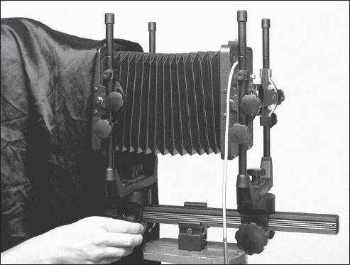
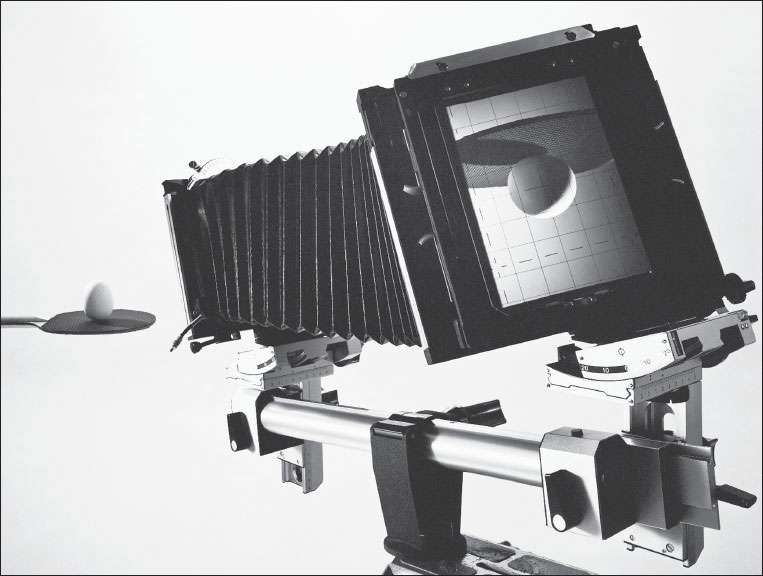
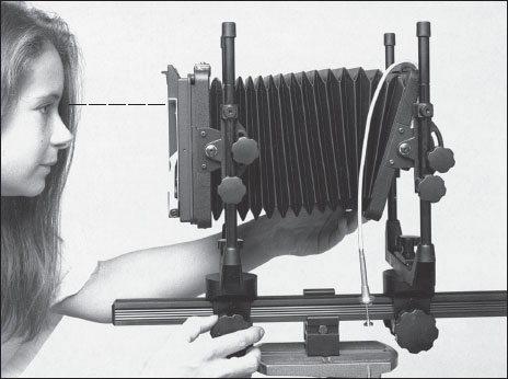
To view through your camera, open the shutter using the press-focus lever (p. 88) and set the aperture to its widest setting. Then, facing your subject, stand behind the ground glass. Cover your head and the rear standard with the darkcloth (p. 141) and look at the image that appears upside down on the ground glass. All lenses invert the image they form but other cameras are designed to reinvert the image (reflex cameras) or else provide an alternate upright image for you to look at (such as a viewfinder image). Remember, in a view camera you are looking at the ground glass, not through it, so your eyes will need to be reading distance away from it. In time, you will find it as easy to work with an image upside down as with one right side up.
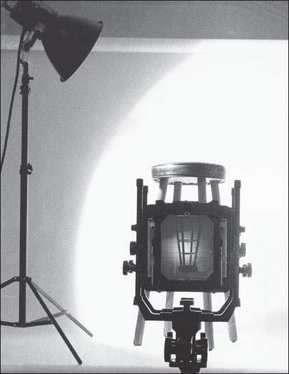
The lens projects an image upside down onto the ground-glass viewing screen. To see it well, your eye should be about the same distance from it as a comfortable reading distance from a book page the same size. ■
After you open the shutter, disengage the focus lock on the rear standard and focus on the scene by moving the rear standard along the rail. Your camera will probably have a focus knob to move the standard by very small amounts. Focus by rocking the knob back and forth past the point you think is the best focus a few times, rocking it less and less each time until you settle on the position for best focus. If you have a fast lens, that is, one with a large maximum aperture, it will admit enough light for you to focus unassisted in bright light, but at smaller apertures and for very precise focusing, hold a magnifying loupe (p. 155) against the ground glass to enlarge a part of the image. Make certain the front of the monorail is not visible in the image at the top of the ground glass. If it is, move the front standard forward on the rail, then refocus. If after viewing the image you decide to change it by moving the camera (or, later, if you change the camera movements), you will also need to refocus.
Although under most circumstances you can adjust the focus equally well with either the front or rear standard, get in the habit of focusing with the rear standard. It is especially difficult to focus close up with the front standard because it changes the magnification and makes the image larger or smaller as you focus. This change results from altering the distance from lens to subject—the object distance. Using the rear standard to focus allows you to find the appropriate focus for an object in a fixed relation to the lens. With a very short object distance it is often easier to move the entire camera or even the subject to bring the image into precise focus.
Lock the focus knob in place after final focusing. Select your working aperture by stopping down until adequate depth of field is visible in the ground glass. These adjustments are judged strictly by eye, so you will need to manipulate the controls from the rear of the camera while under the darkcloth. When the camera is adjusted and focused and the lens is stopped down to the working aperture, close the shutter. After taking your exposure reading, set and wind the shutter. You may wish at this point to check exposure, lighting, framing, and focus with a sheet of instant-picture film (p. 146).
Once you are certain the camera and tripod have been properly adjusted and all of the parts have been locked in place, open the spring back. If your camera has a bail lever, use it. If not, pry back the ground-glass frame a bit with your fingers and insert a loaded film holder (p. 61) against the spring pressure. Hold the camera steady to avoid moving it out of position. With some cameras it may be easier to remove the entire back, insert the holder, then replace the back. If you are using the bail lever, release it gently to prevent the back from snapping shut and cracking the ground glass. The film holder must make a good lighttight seal to avoid unwanted streaks on the film or fogging (fog is an even, overall exposure to unfocused light that lowers contrast and degrades the image quality). If you are unfamiliar with your camera, you may have trouble at first finding this proper seated position. Practice inserting and removing the film holder a few times to make sure you know where the holder is supposed to seat.
Double check the shutter to see that it is closed and then gently withdraw the darkslide (p. 61) from the side of the film holder facing the lens. In dry climates, too rapid a movement of the darkslide may generate enough static electricity to mark the film. If the sun is shining on the camera back, or if there will be a long delay between removing the darkslide and making the exposure, drape the darkcloth over the camera back to protect against possible light leaks.
To begin using your camera, set it securely on its tripod, and make sure all the adjustments are locked in zero position and the shutter is opened for viewing. ■
With the darkcloth covering your head and the camera’s back, focus the image on the ground glass by moving the rear standard along the rail. ■
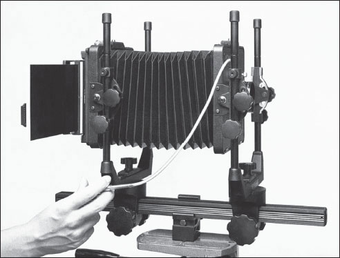
After closing the shutter, insert a film holder and withdraw its darkslide. Make sure the camera is motionless before gently pressing the cable release to make the exposure. ■
Look carefully at the camera for vibration. If you have just taken your hands away from it, give it time to stop moving. If there is a breeze against the bellows, try to wait for a lull. Hold the end of the cable release (p.140) in your hand, leaving enough slack in the cable to prevent motion being transmitted from you to the camera. Make the exposure by pressing the cable release to trigger the shutter. After the exposure is made, insert the darkslide back into the holder with the black rim of its handle facing the outside (a safeguard signifying exposed film) and remove the film holder from the camera.
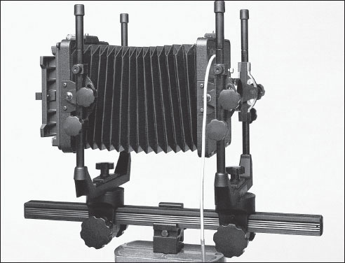
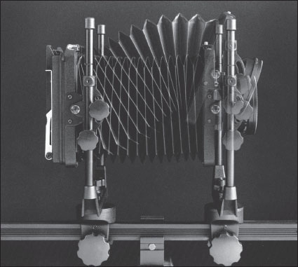
Your view camera’s unique appearance is in part the result of its separately adjustable front and rear standards. Camera movements, the adjustments of these standards, make the view camera unique in function as well as appearance. The importance of adjustable standards is that we can use them to independently alter and control the positions of the lens plane and film plane.
The film plane is the position of the film during exposure, or of the front surface of the ground glass without the film holder in place. With a movable rear standard, the film plane can be angled away from its normal position perpendicular to the rail and to the optical axis, the path of a ray of light passing unrefracted through the center of the lens.
The lens plane is always perpendicular to the optical axis and corresponds roughly to the position of the lensboard (it may in fact be slightly in front of or behind the board, depending on the kind of lens and the thickness of the board and lens mount). With the front standard’s movements, the lens plane may be moved away from its normal position perpendicular to the rail. The optical axis moves with the lens.
Moving the lens and film planes away from their normal positions parallel to each other changes the rendering on film of both perspective and focus. Once you are in control of the effects of these movements, you can create images that would otherwise be impossible. Because the idea of camera movements may be new to you, it may seem intimidating at first. Finish reading this chapter entirely before trying to apply the concepts it introduces. You will need to understand how the camera movements change an image before you can successfully apply that knowledge. Then put your camera through its paces while rereading this chapter. In a short time you will be able to concentrate on the ground-glass image while setting the movements, using no more conscious thought than you need to adjust the focus.
Adding the camera movements to your photographic repertoire will give you pictorial control otherwise impossible, as shown in this photograph by Switzerland’s Fred Waldvogel made for Sinar on their 5×7 Model P camera. ■
The film plane extends in all directions, continuing outward from the edges of the film, or the front surface of the ground glass. ■
The lens plane extends the surface of the lensboard. It is always perpendicular to the optical axis. ■
Always begin with your camera set up in zero (or normal) position with the monorail or camera base horizontal and the lensboard and camera back vertical. The lens plane (lensboard) and film plane (camera back) should be parallel, so that the optical axis will run parallel to the monorail through the center of the lens and the center of the ground glass. Get into the habit of returning the camera to the zero position after each photograph.
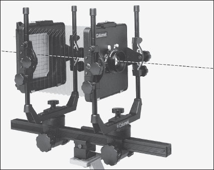
The optical axis is an imaginary line through the center of the lens, perpendicular to the lens plane. ■
Adjusting the front and rear standards to control the image requires some combination of three motions: shift, swing, and tilt. These camera movements are adjustments of the plane and position of the lens and film and are sometimes referred to as “swings and tilts.”
A tilt is a movement of the lens plane or film plane around a horizontal axis perpendicular to the optical axis. Nodding your head as if to answer “yes” would be a tilt of your face.
A swing is a movement of the lens or film plane around a vertical axis perpendicular to the optical axis. Shaking your head to say “no” is a face swing. Swings and tilts are both inclining movements and produce an angular change in the position of the lens or film plane.
A movement of the lens or ground glass that leaves it in the same plane is called a shift. For example, in a lens shift you would slide the lens to the side or up or down and produce a lateral or vertical displacement of the optical axis. Opening a sliding door or a sash window is a shift movement. A vertical shift is often called a rise or fall.
What the Movements Do
The camera movements increase your ability to control two important aspects of a photograph: the rendering of perspective and the position of the plane of focus through the image. Perspective means the relative sizes of objects in the image, and the plane of focus is that plane in front of the lens in which all points are in focus, independent of depth of field. Although the effects of front and back movements can overlap (shifting the front up gives almost exactly the same results as shifting the back down), and although a single movement of one standard can affect both plane of focus and perspective, the swings and tilts are best understood if you mentally separate the functions of the front and back. As a rule of thumb, use the position of the lens plane to control plane of focus and the position of the back to control perspective.
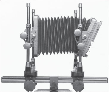
The camera in zero (or normal) position. ■
The illustrations on the next few pages show the camera movements—swing, tilt, and shift—in extreme positions for clarity. In normal use, you will rarely need to adjust your camera so far from zero position. ■
Front tilt, sometimes called lens tilt. ■
Back tilt. ■
Front or lens swing. ■
Back swing. ■
Vertical lens shift, nearly always called front rise. ■
Vertical lens shift: front fall. ■
Front or lens shift. ■
Back rise. ■
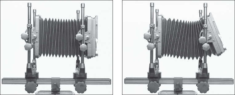
The actual positions of the lens and film will affect your photograph, not how you got them into those positions. The effect on your photograph of a front and back tilt on an inclined rail…
… is exactly the same as the effect from a front rise on a horizontal rail. ■
CONTROLLING PERSPECTIVE: BACK MOVEMENTS
In your past experience as a photographer you have probably found that one of the most important controls at your disposal is camera placement. This may seem obvious; if you put the camera in the forest, you will make a different photograph than you would in the city. And a photograph made from above your head will be different from one made at knee level. These considerations of vantage point are extremely important to the making of photographs with any camera.
Vantage point is the position of the lens in space and determines perspective, that is, the relative sizes of near and far objects in your image. Perspective is also the relative sizes in the image of near and far parts of the same object so, as a direct consequence, perspective controls the appearance of the shape of objects. The perspective in your photograph will ordinarily be the same as what you would see with one eye if it were viewing the scene from the same position as the lens. If you can alter the position of the back of a camera, and therefore the position of the film relative to the optical axis, you can alter this apparent perspective in your photographs. Once you have placed your lens for the desired vantage point, your view camera allows you to control the appearance of the image further by altering the position of the back.
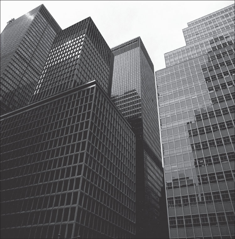
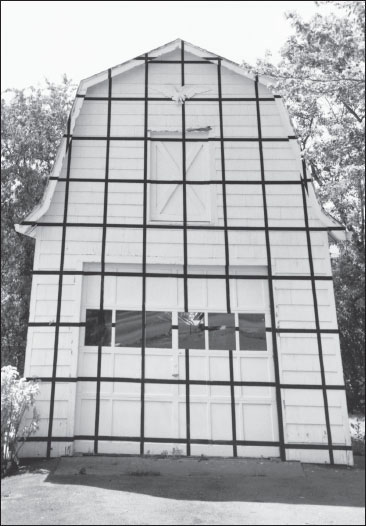
In this 1969 photograph of New York City buildings, Harry Callahan made intentional use of the keystone effect, the convergence of vertical lines that is a natural consequence of tilting the camera up. ■
Back Tilt
As an example of the kind of perspective control a view camera can give you, use a 35mm camera (or any camera having back and lens in fixed positions) at ground level to photograph all of a tall building. The building, having vertical, parallel sides, will appear in the photograph to be narrower at the top. This effect, called the keystone effect, is the result of tilting the camera up to include the top of the building. The top of the building appears smaller than the bottom because it is farther from the lens and the parallel sides of the building appear to converge toward the top.
To avoid the keystone effect with your view camera, you can tilt, or incline, the back independently of the rest of the camera. When you do, one end or edge of the film ends up closer to the lens than the other. The cone of light projected rearward by the lens (p. 78) gets larger as it moves away from the lens. When you incline the film plane, the image on the part of the film farther from the lens becomes larger than that part closer to the lens. This tilt will diminish the appearance of convergence toward that side of the image.
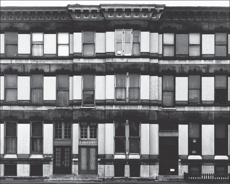
An earlier photograph by Callahan, from Dearborn Street in Chicago, 1948, exhibits vertical lines of the building carefully made to appear exactly vertical in the photograph. Callahan’s mastery of the camera allows him to select and control convergence to his own aesthetic advantage. ■
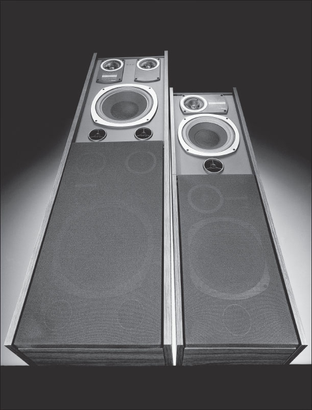
Opposite: Vertical convergence was exaggerated with back tilt for dramatic emphasis in this advertising photograph made for the loudspeaker manufacturer by Geoff Stein. ■
Because the lens inverts the image, the top of the building in the example above appears at the bottom of the ground glass. Tilting the back, now leaning with its top away from the building, toward a vertical position moves the image of the top of the building (seen at the bottom of the ground glass) away from the lens, making it larger or wider, and the image of its bottom (at the top of the ground glass) toward the lens, making it smaller or narrower. If the back is adjusted this way until the top and bottom of the building appear to be the same width in the image, its sides will appear both vertical and parallel.
This tilting procedure alters the normal perspective of the image. Your eye, like a fixed-back camera, actually forms an image of the building with its top narrower. Your brain usually ignores that data, however, because you know the sides of the building are parallel. Some photographers refer to this kind of perspective alteration in a photograph as “correcting” because it makes the image appear as we perceive the building, not as we see it.
Photographs of buildings are the most obvious examples of the need for this kind of perspective control. When architects and builders carefully design and construct buildings having parallel sides they like to see their efforts clearly demonstrated in photographs of their buildings. This preference is particularly strong when they are paying for the photographs.
The Vanishing Point and Convergence. When you make photographs, remember first that the relative sizes of near and far objects (and of near and far parts of the same object) are determined by where you place your lens. The vanishing point is the point at which parallel lines or surfaces receding from the camera position appear to converge. Because tilting the back increases or diminishes convergence, it also moves the vanishing point closer to or farther away from the center of the image. Once you have selected a specific vantage point, you may further modify the perspective by altering the location of the apparent vanishing point with the position of the camera’s back.
Tilting the back controls vertical convergence. When the camera back is vertical, all vertical lines in the scene appear as parallel vertical lines in the photograph. If the back is tilted away from vertical, as in the previous example with the tall building, vertical lines in the scene will converge in the photograph. If convergence is desired, as in the photograph of the loudspeakers on the opposite page, it can be exaggerated; the farther from vertical the back is tilted, the greater the convergence.
Note that increased convergence means that the vanishing point moves closer to the center of the image. The results of tilting the back are easiest to understand by looking at vertical lines, such as building sides in an architectural photograph. But even in an image containing no straight lines, such as a landscape, moving the vanishing point profoundly affects the appearance of the photograph.
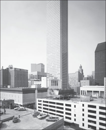
Using a wide-field lens and a front rise, in addition to unusual cropping, architectural photographer Paul Hester made this Houston high rise seem limitless. ■
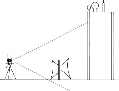
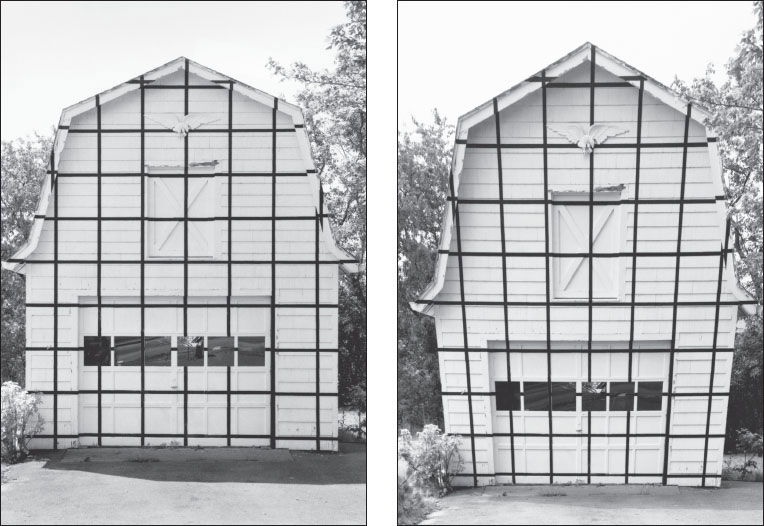
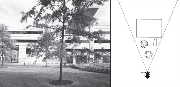
Pointing the camera straight at a tall building from eye level will result in a photograph that includes a great deal of foreground but lacks the top of the building. ■
Pointing the camera up to center the building in the frame results in a photograph that shows the sides of the building as converging lines. The bottom of the building is closer to the camera than the top and is represented in normal perspective by appearing larger. ■
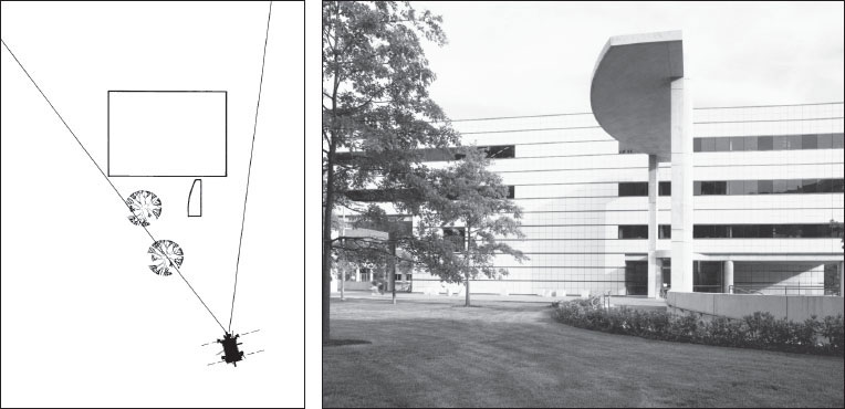
Tilting the back of the camera moves the bottom of the focusing screen, with the image of the top of the building, farther from the lens than the top of the focusing screen with the image of the bottom of the building. The image formed by the lens grows larger as it moves back away from the lens in the projected cone of light, so the image of the building’s top is made larger to appear the same width as the image of the bottom of the building. ■
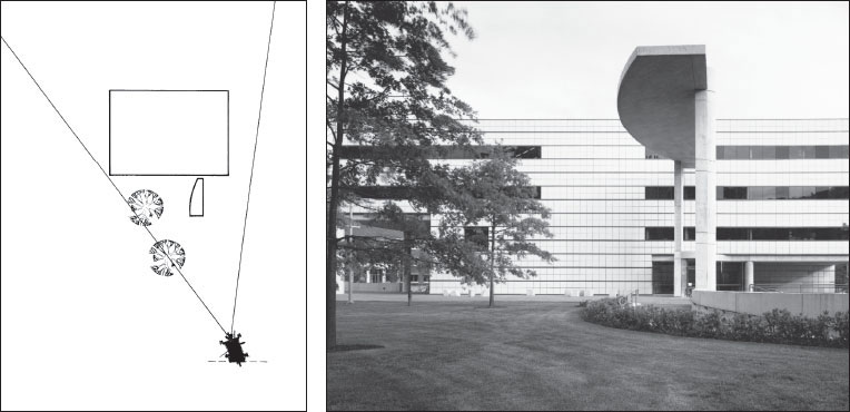
These three photographs were made from the same camera position and show the effects of back tilt on vertical convergence and the location of the vanishing point. ■
The front of this building shows its horizontal lines parallel (without horizontal convergence) because it was made from a position exactly in front of the building’s center. Unfortunately, there is also a tree in a position exactly in front of the building, making the value of this vantage point questionable. ■
Back Swing
While back tilt controls vertical convergence, back swing affects convergence (the position of the vanishing point) for horizontal lines. When a horizontal line on the back of the camera is parallel to horizontal lines in your subject, as in a head-on photograph of a house, the horizontal lines in the image will all be parallel and horizontal. Pointing the camera at the same house from a position on either side of head on, with the camera back at an oblique angle to the front of the house, the horizontal lines will converge away from the camera. Swinging the back from this position to be more parallel with the front of the house will reduce this convergence; swinging it farther away from parallel will exaggerate it.
In the two series of photos on the following pages, placing the camera in position for a head-on photograph eliminates convergence as easily as using the back swing. The swing movement is most useful when your access to a desired vantage point is limited, for example by a tree or car in front of the house. This is why the back tilt is more often used than the swing; a vantage point head-on to a horizontal surface is easier to achieve (say, by walking around a building) than one head-on to a vertical surface (which might require a very tall ladder). Your own mobility is often much greater horizontally than vertically.
The advantages of swing and tilt control are most evident when you are photographing man-made objects because their regular shapes make convergence more noticeable. This is why the view camera is indispensable when photographing architecture or for advertisements. Remember that nature’s forms are no less affected by moving the vanishing point, however, and creative control is at your fingertips when using a view camera for landscapes.
From a vantage point slightly to the side, the building’s elevation is clearly visible, the tree is on the left edge of the frame, but the horizontal lines converge to the left. ■
By using a back swing, making the back parallel to the building’s facade, the horizontal lines are made parallel in the photograph made from this vantage point. ■
These three photographs made from exactly the same camera position show that back swing can be used to introduce and control horizontal convergence, without altering the vantage point. ■
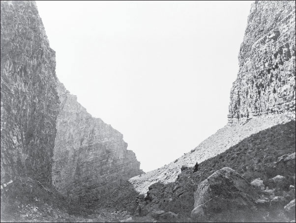
Timothy O’Sullivan made this photograph of Colorado’s Vermillion Creek Canyon in 1872 for the U.S. Geological Survey. ■
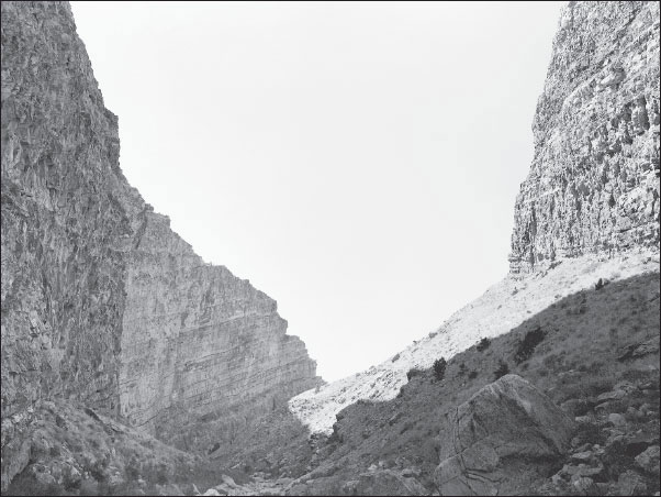
For the Rephotographic Survey Project, Mark Klett made this photograph in 1979 from O’Sullivan’s original vantage point showing this particular section of our western landscape to be virtually unchanged in over a century. ■
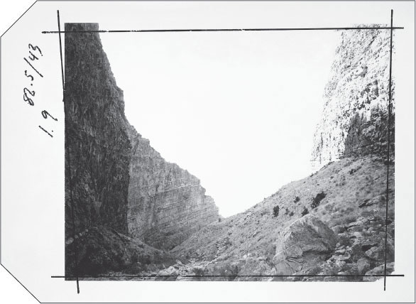
Klett’s precise methodology reveals O’Sullivan’s use of camera movements for perspective alteration. This Polaroid instant-print field check of camera position made without camera movements has the borders of O’Sullivan’s photograph drawn in. Their trapezoidal shape indicates that an angular displacement of the camera back is necessary to recreate the perspective shown in the 1872 photograph. ■
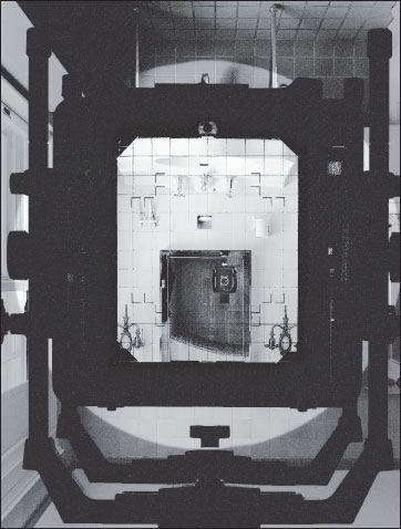
Without camera movements, a head-on photograph of this environment reveals the camera’s reflection in the mirror. ■
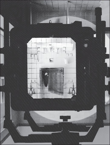
Moving the camera to the side removes the reflection in the mirror; the image circle from the lens is large enough to allow a back shift to adjust the framing of the image. ■
Back Shift
Back shift movements—rising, falling, and lateral shifts—do not alter the perspective of the image, but they do alter the image in other ways. Think of the image projected by your view camera lens onto the film as the one projected by a slide projector onto a screen. If the slide projector is too far from the screen, the image you see on the screen is only part of the image on the slide—the extra spills over the edges of the screen. By moving the screen from side to side and up and down, you can make different pictures appear on the screen, each a different section of the whole slide.
In a similar manner, most view camera lenses project an image somewhat larger than the film (see coverage, p. 75) and you can shift the back of your camera side to side and up and down to select the desired part of that larger image. In this way you can make adjustments to the framing of an image without moving the entire camera and with no change in perspective or vantage point.
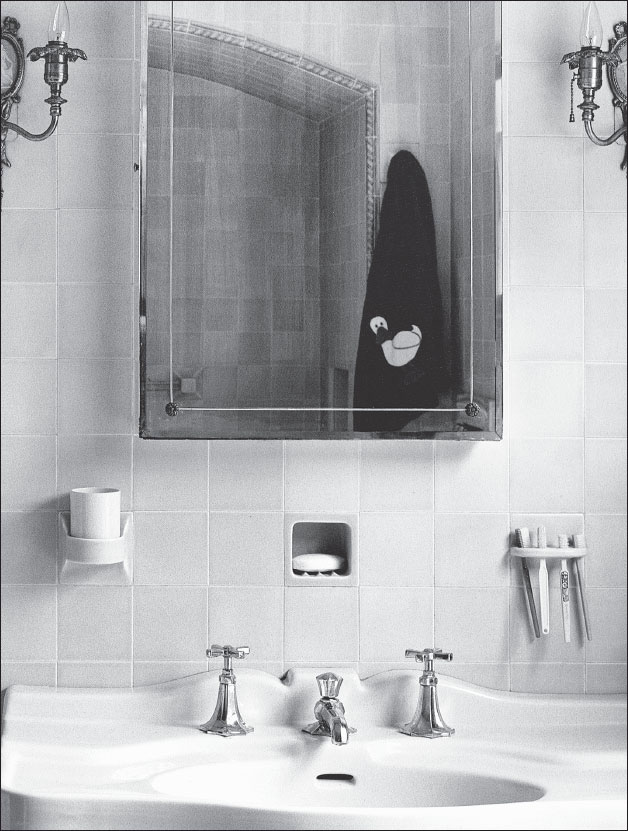
The resulting image avoids the camera’s reflection in the mirror yet still allows the pattern of tiles to be reproduced without convergence. ■
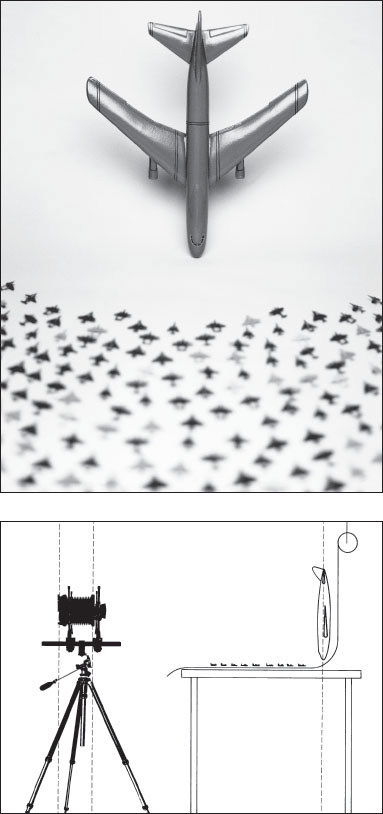
Set up in zero position and focused on the single large jet in the back, the plane of focus is vertical; the limited depth of field throws the foreground out of focus. The appearance and position of the plane of focus are the same as they would be using any hand camera. ■
CONTROLLING PLANE OF FOCUS: LENS MOVEMENTS
With a rigid-bodied camera such as a 35mm, the lens plane and film plane are parallel and fixed in relation to each other. The only relative movement allowed is changing the distance between the two to focus. When this distance is adjusted so that a point two meters from the lens is in focus, an entire plane through that point, parallel to the lens and film planes, is in focus as well. Adjusting the focus to three meters moves this plane of focus one meter farther away. This plane of focus is always a two-dimensional surface slicing through a three-dimensional world.
When your view camera’s lens plane and film plane are parallel, the plane of focus behaves in exactly the same way as that of any rigid-bodied camera. You have the option, however, to adjust the lens and film planes away from their normal parallel position. A swing or tilt of either lens or back will move the plane of focus to a new position parallel to neither lens nor film plane. Understanding and applying this control will make it possible for you to make great photographs in otherwise impossible situations. If, for example, you were photographing across a tilled field, with your camera aimed at the horizon, tilting the lens plane by moving the top of the lensboard forward would move the plane of focus to cut horizontally across the surface of the entire field. In this way you would have the entire field in focus, foreground to background, without having to use a very small aperture to get great depth of field. The larger working aperture would allow the use of a faster shutter speed, perhaps to stop the action of workers moving in the field. In addition, the wider apertures (but not the widest) of any lens will usually produce an image with greater sharpness than the smaller apertures on the same lens.
In the following section, you will learn how the angle between the lens plane and film plane determines the position of the plane of focus. When you change that angle by moving either lens or film plane, you will change the plane of focus. In the previous section we found that perspective depends on vantage point and can be altered by the position of the film plane. Perspective is not altered by angular movements (swing or tilt) of the lens plane. Because of this, your chosen perspective will be unaffected by adjusting the plane of focus if you make that adjustment with the lens plane and not with the back. To save steps, select your vantage point first, then adjust convergence with the back, and finally alter the lens plane if you wish to move the position of the plane of focus.
The Scheimpflug Principle
When the lens and film planes are not parallel to each other (a situation usually possible only with a view camera), an unusual set of optical conditions exists in which the plane of focus cuts at an angle through the image. The rule governing this peculiar situation was named after a Prussian army officer of the nineteenth century who was presumably the first to quantify the results. The Scheimpflug (shīm’-floog) Principle states that when the lens plane and film plane are not parallel, neither will be parallel to the plane of focus. Fortunately, the Scheimpflug Principle also tells us where the plane of focus will be: it will meet the lens plane and film plane in a line.
Front Tilt
To visualize the effects of the Scheimpflug Principle, imagine your camera set up in zero position. If you stand close to the camera back, the film plane passes through your toes (remember the film plane doesn’t stop at the edges of the film). If you tilt the lens-board forward so that its extended surface (the lens plane) also passes through your toes and you adjust the focus properly, then the plane of focus will be the floor. In other words, with the back vertical and the lens tilted forward, the surface of the floor will be entirely in focus—the plane of focus will be horizontal. The planes of the lens, film and floor meet in a horizontal line, perpendicular to the rail, at your toes.
Front Swing
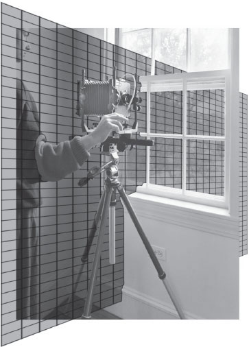
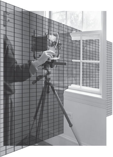
If you set your camera at an oblique angle to a long wall, you can swing the front standard so that the lens plane meets the vertical line where the film plane cuts the wall. The surface of the wall will then be the plane of focus. In this way, the plane of focus may be made to lie along any vertical, flat surface.
Once you get used to the notion that the plane of focus needn’t be parallel to the film and can visualize the positions of the film plane and lens plane beyond the edges of the ground glass and lensboard, it will be easy for you to use the Scheimpflug Principle to your advantage.
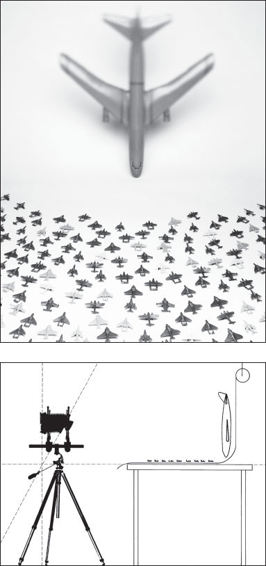
With the lens tilted so that the lens plane and film plane meet in a line with the horizontal plane of the tabletop, the plane of focus is now horizontal, leaving the vertical jet out of focus. The position of the back of the camera and therefore the rendering of perspective remains unchanged. ■
This diagram shows the limits of the depth of field at several aperture settings, around a plane of focus repositioned using the Scheimpflug Principle. Though the plane of focus has been repositioned by a lens shift, as it is here, and this diagram looks quite different from what you might be used to, the behavior of the depth of field is essentially unchanged by the Scheimpflug Principle. ■

The small globe and star-studded juggling ball were props from an unrelated series that Jim Henkel was making when this poetic idea, titled Observatory, materialized. A lens tilt moved the plane of focus to near horizontal making the feet fall out of focus as a metaphor for distance. ■
Front Shift
Shifting the front in one direction has almost exactly the same effect as shifting the back in the opposite direction. A lens shift, however, introduces a change in vantage point. For a distant scene, moving the vantage point only a few centimeters will not produce a noticeable change in the image, so you can often use a front rise interchangeably with a back fall. In situations where small adjustments of vantage point are needed, such as close-up work, use the lens shift for exact placement of the vantage point, then use the back shift to adjust the exact framing of the desired image.
Theoretically, a lens can only focus sharply on a flat, two-dimensional surface, the plane of focus. In practice, however, your eye is unable to distinguish between the sharpness in the image formed of a point in the plane of focus and that of one slightly closer or farther which is only slightly unfocused. The distance between the near and far limits of what we see in the image to be in focus is the depth of field and it is always measured perpendicular to the plane of focus. Depth of field affects profoundly the appearance of your photographs by determining what appears to be in focus; it therefore deserves careful attention during the making of any photograph.
With your view camera in zero position, the behavior of the depth of field conforms to the same rules it obeys in any rigid-bodied camera. The lens and film planes are parallel, and the near and far limits of the depth of field are planes parallel to the lens plane, the film plane, and the plane of focus. For a given object distance (from the lens to the plane of focus), the distance included in the depth of field will increase with smaller apertures. For a given aperture, depth of field will increase for greater object distances. For very short object distances, the plane of focus is near the center of the depth of field. There is an old adage about the plane of focus having one-third of the depth of field in front of it (toward the camera) and two-thirds behind it; this is generally accurate at middle distances (say, across the room or across the street). At greater distances, the depth of field increases to a much greater extent behind the plane of focus than in front of it.
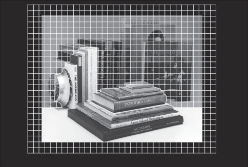
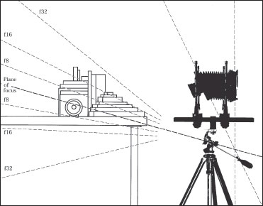
With the camera in zero position, the plane of focus cuts through these books vertically. With a normal lens and at this vantage point, it would be impossible to achieve enough depth of field to include both foreground and background in focus. ■
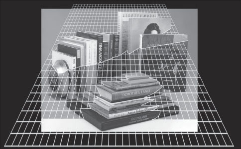
By tilting the lens according to the Scheimpflug Principle, the plane of focus was tilted to cut through this image from lower foreground to upper background so that all the objects could be brought into focus with the minimum depth of field. In this case, closing the aperture by only two stops was sufficient. Using the Scheimpflug Principle allows you to find and use the most advantageous position for the plane of focus in any photograph. ■
The behavior of the depth of field is altered by the Scheimpflug Principle, though not beyond recognition. Depth of field still is increased by smaller apertures and greater object distances and still surrounds the plane of focus. Since all parts of the plane of focus are not at the same distance from the lens, however, the depth of field is not the same in all parts of the image. Depth of field increases as the plane of focus recedes from the camera. At smaller apertures, it increases more rapidly with distance.
Depth of field is affected by aperture, object distance, and lens plane adjustments, but it depends especially upon what is considered acceptable sharpness for your use. Judgment of acceptable sharpness is subjective and hinges on such factors as viewing distance and degree of enlargement for the final print. To supplement experience for increasing your ability to make judgments about depth of field, there are standard tables and scales based on average values of the factors affecting depth of field. These tables are also available as smartphone apps that are very useful in the field.
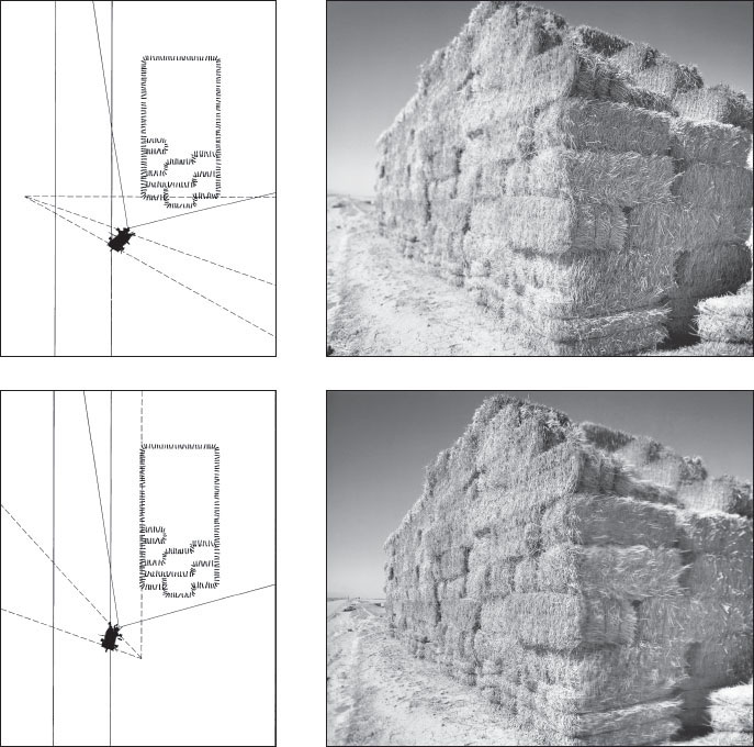
The lens swing was used to line up the plane of focus with one face of this pile of hay bales and then with the other face from the same camera position. A wide aperture limited the depth of field so that the positions of the plane of focus are easily visible. ■
Along with a wide aperture, David Graham says he used a lens swing “in opposition to any logical approach to a landscape photograph.” The altered plane of focus conspires with limited depth of field to produce an unsettling isolation of elements. ■
As in a painting or any other two-dimensional pictorial representation, the illusion of depth in a photograph depends upon four factors: 1. Atmospheric effect is the softening of detail with distance, as though the scene were viewed in a haze. In a photograph it is controlled by your selection of film and filters, time of day, and focus. 2. Lighting can be controlled in the studio or selected outdoors to give the illusion of compressed or expanded distance. Soft, nondirectional light, for example, compresses distance. 3. Interposition of objects, the way a foreground object hides what is behind it, is primary information for the eye in judging relative distances. An object with its contour interrupted by that of another object appears to be behind the object interrupting it. 4. Linear perspective, the relative sizes of objects in the image, causes objects in the foreground to appear larger than objects of similar size in the distance.
Linear perspective is wholly the result of vantage point (lens position). The closer you position your lens to an object, the larger it will appear in relation to objects behind it. The effects of linear perspective are independent of lens focal length (p. 79), even though you might assume that a wide-angle lens will render a different perspective from that of a long-focus lens. This misconception results from the fact that a wide-angle lens must be much closer to an object to make the image of that object the same size on a negative. The closer position changes the perspective by making other, distant objects relatively smaller, hence the assumption that shorter lenses exaggerate perspective. From the same camera position, however, all lenses will represent objects in the same relative sizes.
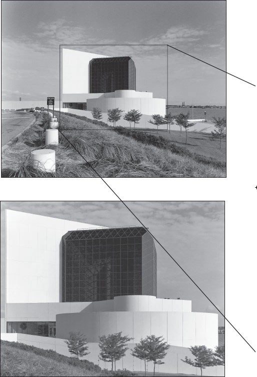
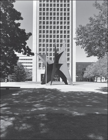
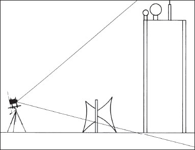
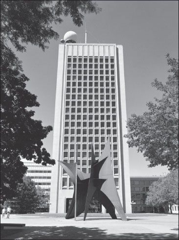
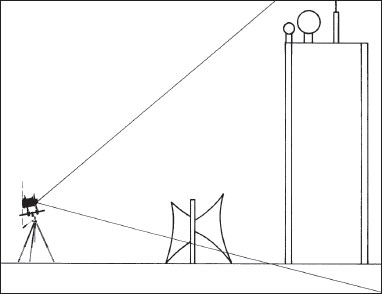
This photograph of the John F. Kennedy Memorial Library was made with a wide-angle lens, in this case a 90mm lens on a 4×5 camera. ■
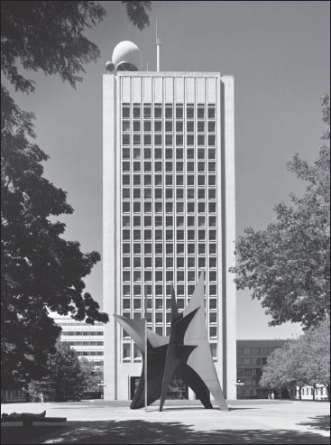
Made with a 180mm lens from exactly the same camera position—therefore an identical vantage point, this photograph shows every part of the image to be exactly twice as large as the one above, made with a lens having half the focal length. ■
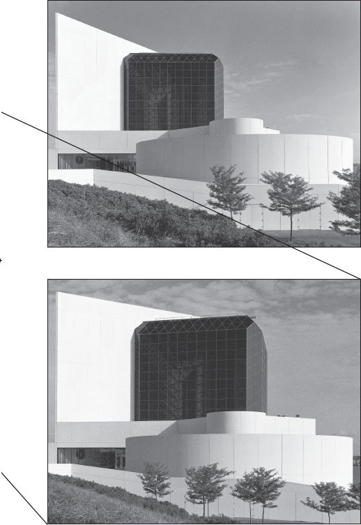
Making a photograph with the 90mm lens to include the same boundaries as one with the 180mm lens requires a much closer camera position (vantage point), therefore the perspective appears completely different. This rendering of perspective is not the result of using a wide-angle lens, but is the result of close position. ■
Enlarging the center section of the first wide-angle photograph (upper left) gives exactly the same perspective as that rendered by the longer lens from the same position (lower left). Perspective depends entirely upon vantage point and not at all upon focal length. ■
SETTING UP A PHOTOGRAPH: A COMPLETE SEQUENCE
After you have read the section on lenses (Chapter 5) and if you are fortunate enough to have a selection of lenses from which to choose, a simple sequence of steps can lead you to exactly the photograph you want. You will eventually integrate these steps into your procedure for setting up the camera, and your mind will be free to concentrate on the desired image.
1. Select a vantage point for the desired perspective. Where you put the lens and when you make the exposure are the most important decisions you must make for each photograph. Remember that the selection of a lens is not a factor in the control of perspective; if you close one eye you will see objects in the same relative size—with the same linear perspective—as with any lens you choose. The vantage point is determined entirely by the position of the lens; use the placement of the camera as a rough control and the lens shift for fine-tuning.
2. Select the focal length of the lens for the angle of view (p. 80), the section of the scene in front of the lens you wish to include. If you don’t have the exact lens you need, you can use a shorter focal-length lens (one having a wider angle of view) and plan to crop out the unwanted part of the image later. If you substitute a longer lens (one with a smaller angle of view), it will leave out part of the desired image or force you to move the camera farther back. If you move the camera, you will change the size relationships you determined in selecting your vantage point.
3. Once you have selected a lens and established a perspective based upon a specific vantage point, adjust the back to contour the perspective to your needs. By combining tilt and swing movements you can adjust convergence (move the vanishing point) not only horizontally and vertically but to any angle in between. More often than not you will want the back vertical. This is such a common working position that many cameras provide a small bubble level—often two—on the rear standard to aid in determining a precisely vertical position. If your camera is not so equipped, bubble levels are available as an accessory.
4. Select a plane of focus. Basing your judgment on the parts of the scene you would like to appear in focus, imagine the plane slicing through the scene in a position that will give you that focus with the least possible depth of field. As with the adjustments of the back, lens swing and tilt can be combined so the plane of focus can cut through the subject at any angle. Select the placement of the plane of focus carefully so you can achieve the depth of field you need without having to stop down the lens beyond its sharpest apertures (see diffraction, p. 120). Pick three points in your image to define the desired plane of focus. These points will form a triangle to help you visualize the surface of the invisible plane cutting through the image. The farther apart the three points, the more accurate you can be in isolating that particular plane when you adjust the lens plane. If your image allows it, one of your selected points should be in the extreme background and the other two on the extreme left and right of the foreground.
To determine exactly how much to tilt the lens for your selected plane of focus, you should approach the correct setting gradually, in steps. Pick a point in the foreground and one in the background that you would like to include in the plane of focus. Select these points from the scene beforehand, not from the ground-glass image. Keep one hand on the focus adjustment of the rear standard and the other on the tilt adjustment of the front standard. Bring the foreground point into focus and then refocus for the background point. Make a mental note of the amount you had to turn the knob to refocus between them. ■
5. Adjust the lens tilt to bring two of your selected points, one near and one far, into focus simultaneously. While you are under the darkcloth viewing the ground-glass image, use one hand to tilt the lens and the other to focus with the rear standard. Before you tilt the front away from zero position, focus on one, then the other, of your selected points. Notice how far you have to move the back to focus from one to the other. Change the angle of the lens slightly in the direction indicated by the Scheimpflug Principle. Adjusting the lens tilt moves the plane of focus away from the vertical around a horizontal axis at right angles to the monorail. Remember, the plane of focus and the lens and film planes will meet in a line. Once more, focus on one point, then the other again, back and forth, and check to see whether the distance you have had to move the back to focus from one to the other has decreased. If so, the two points are closer to being in focus simultaneously, that is, closer to being in the plane of focus.
Tilt the lens a few degrees in the direction indicated by the Scheimpflug Principle; for a tabletop plane below camera level, you will need to tilt the top of the lensboard forward. Focus again on the two points, first one then the other. The amount of refocusing needed should diminish. Tilt a little more and then refocus again. As you proceed, the distance between correct focus for the two points will get smaller and smaller until they are both in focus at once. If you find you need to move the focus farther each time, you have passed the correct tilt and are moving away from it. ■
Continue to adjust the lens tilt by very small amounts. Focus both points after each adjustment to check that the distance between their focused positions continues to decrease. If it has decreased, you are approaching the lens angle at which the focus position is the same for both points, meaning that both points will lie in the plane of focus.
If you adjust the lens tilt by a small amount and find that you must increase the distance you move the focus adjustment between the two points, you have moved the lens past the correct position, or in the wrong direction. For most photographs, the amount you will have to tilt the lens away from normal position will probably be quite small, so use very tiny adjustments of the angle.
6. Use the lens swing to tip the plane of focus left and right. If your two foreground points require a focus plane slanted from side to side, use the same procedure as above to adjust the lens swing until both points are simultaneously in focus. When you have found the correct position of the lens and they are both in focus, check the near and far points again. Unless your lens has been rotated (with the swing) exactly around its rear nodal point (p. 115), you will probably have to readjust the tilt very slightly. The thickness of your lensboard and lens mount will affect the position of the nodal point, and the design geometry of your particular camera (see the next section) decides the exact axis around which the lens swings.
7. Select the working aperture. Once the plane of focus has been properly positioned, close the diaphragm until you see the desired depth of field in the ground-glass image.
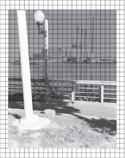
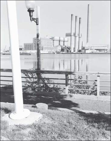
Focusing on the wooden lamppost with the camera in normal position results in a plane of focus that cuts vertically through the scene. It is not possible to bring the entire scene into focus by closing down the aperture for depth of field. ■
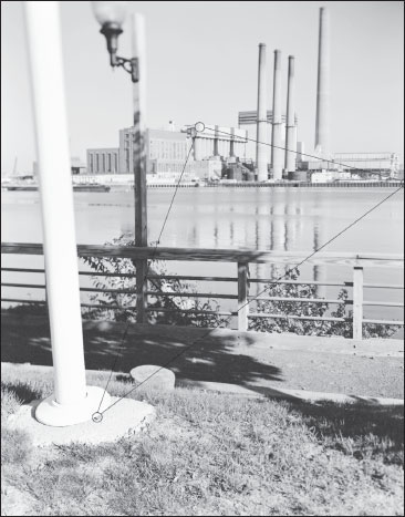
Choose three points in the scene to define the position for your adjusted plane of focus. They should appear relatively far apart on the ground glass and be sharply defined to make your job of adjusting and focusing easier. ■
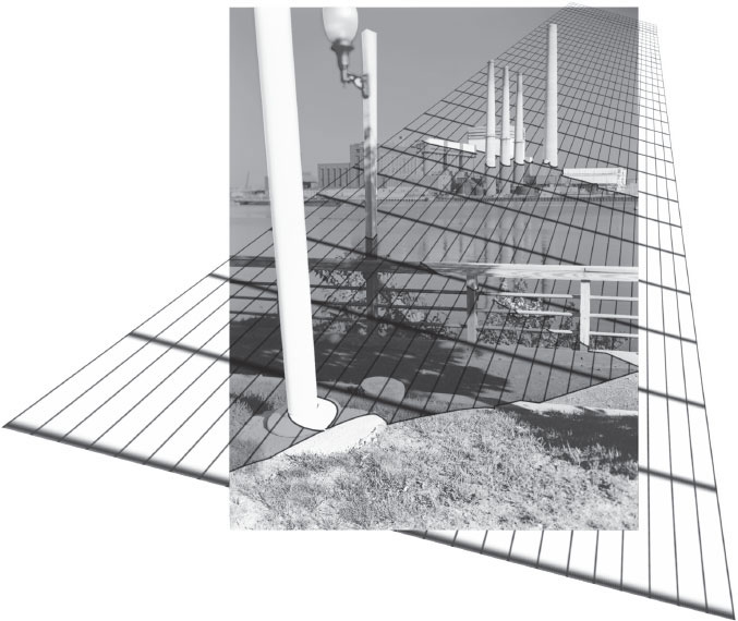
This plane of focus was selected to allow all of the image to be brought into focus with the largest aperture (the minimum depth of field) possible. It required both a tilt and swing of the lens plane. Here, with the lens wide open, it shows the plane of focus cutting through the image. ■
Closing down the lens to a middle aperture created enough depth of field for convincing sharpness in the final image. ■
These two photographs show the results of adding a front rise to a tilted lens with two different cameras. This camera uses axis tilts. ■
This camera, having base tilts, requires more refocusing after adding one camera movement to another. ■
Not all cameras are designed to have the tilt pivot in the same position. Most monorail cameras offer axis tilts, meaning the lens and ground glass tilt around their own centers on a horizontal axis. Some use base tilts, in which the front and rear tilts pivot around a horizontal axis at the base of the standard. Current flatbed designs—field, press, and technical cameras—have backs that tilt from the base. Although you can make exactly the same photograph using a camera with either base or axis tilts, this design difference can make some unexpected differences in the operational steps needed to achieve that image.
In cameras having either axis or base tilts, a rise or fall is a movement of the lensboard or back along the upright member of the standard. With axis tilts, the standards themselves are always perpendicular to the rail, but the standards on a base-tilt camera tilt along with the lens or back.
Tilting the lens on a base-tilt camera will move it farther from the film, changing the image distance; once tilted, a vertical shift will change the image distance once again. Also, tilting the lens at the base moves the lens away from the swing axis. In other words, adding a swing to a base-tilted lens moves the whole lens in a circular path rather than rotating it around the vertical swing axis. Swinging the lens in an arc moves the nodal point of the lens, thereby requiring considerable readjustments of focus and tilt. Axis tilts have the advantage of requiring less refocusing of the image after each movement, but have the disadvantage that an extreme back tilt can block insertion of the film holder.
At least two monorail cameras, Arca and Rajah, include both axis and base tilts. The Sinar p2 pioneered an unusual system, now available from other manufacturers, that tilts back and lens around an axis between base and center, using a very sophisticated geometry to simplify the focusing and adjustment process. Although many photographers express strong preferences for one system or camera, the technique of adjusting any of the available cameras will rapidly become second nature with practice.
Bellows Extension Factor
The only limitation to focusing on close objects with your view camera is the length of your bellows, and you can remove even that limitation by adding an additional standard and another bellows. This freedom to focus on nearby objects is one of the great virtues of the camera, but exercising it introduces you to another important photographic principle. This principle, the Inverse Square Law, is ordinarily hidden from users of small cameras by the designers of those cameras.
The illumination available from a light source depends upon the distance from it. Imagine a long, windowless corridor with only one light bulb at one end. The farther from that light bulb you stand, the darker it is where you are and, for example, the harder it would be to read by that light. The film in a view camera is also in a long, windowless corridor—the bellows—and the lens is the light source. Bellows extension is the length of that corridor. The more closely you focus, the longer the corridor you make for your film—the greater the bellows extension—and the farther the light is from the film. This means that by decreasing the object distance, the intensity of the light reaching the film is diminished.
Most photographers whose experience is limited to small cameras assume the light intensity reaching the film is only affected by the light level of the scene and by the selected aperture. Within certain limits, this is not a damaging misconception. With any camera, a normal exposure is based upon an infinity focus, at which the lens and film are one focal length apart. Focusing on a closer object moves the film farther from the lens, diminishing the light intensity. In order for the light intensity to be diminished by a noticeable amount, however, the object distance has to be less than about seven times the focal length. Since the focusing mounts for most small camera lenses are intentionally designed to prevent their use at object distances less than seven times their focal length, users of these lenses can produce satisfactory work within the limits of their equipment and in ignorance of bellows extensioneffects.
Your view camera has no built-in barrier to keep you from focusing more closely than seven times the focal length. If you do, you will reduce the illumination reaching the film plane enough to need to compensate for the light loss. The bellows extension factor is the measure of this necessary exposure compensation.
You can calculate the bellows extension factor and multiply the measured (uncompensated) exposure by it, or you can make an educated guess at the needed exposure increase. But in order to do either it is important to know how far the film is from the lens. All your normal exposure calculations are based on an object distance of infinity, the shortest bellows extension possible with a given lens. This is your starting point. At infinity focus, the lens and film are separated by one focal length. With a 300mm lens at infinity focus, the lens and film are about 12 inches apart (remember that 25mm is approximately 1 inch). With this lens, which you might choose for general use on an 8×10 camera, you will need to calculate a bellows extension factor when you focus more closely than about 2 meters, or almost 7 feet. Once you have focused inside this range, measure (or estimate) the actual distance between lens and film.
The Inverse Square Law is the principle of physics governing bellows extension and, like other laws of nature, it cannot be ignored without consequence. It tells us that the intensity of a light source diminishes with the square of the distance from it. In our long corridor, if you move twice as far from the bulb, you are illuminated one-fourth as much. At three times the distance, you are illuminated with one-ninth the light. Similarly, if you are using a 150mm lens and want to make a photograph with the bellows extended to 300mm (12 inches), you will need four times the normal exposure. With the film twice as far from the lens as the infinity focus on which a normal exposure is based, the illumination is diminished to one-fourth normal and the exposure must be increased by a factor of four, or two extra stops.
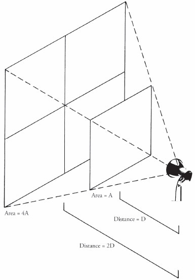
The illumination from this lamp thatfalls on the close card would have to cover a cardfour times the area if it were twice the distance away. The area for the same illumination increases as the square of the distance. ■
There are several methods and formulas for calculating the bellows extension factor and they will all result in the same compensation. The simplest formula is this: the bellows extension factor is equal to the extended bellows length squared, divided by the focal length squared. The indicated exposure (the one determined by metering) should be multiplied (increased) by this factor. You can increase exposure by using a larger aperture or a slower shutter speed.
With most black-and-white work, a careful estimate of the exposure compensation will be sufficient. With color materials, especially reversal film, measurement and calculation will be necessary. Copy work almost always demands compensation for bellows extension because short object distances are common.
Reciprocity Failure
The Law of Reciprocity tells us that the correct exposure for a given film in a given lighting situation may equally well be any of several equivalent combinations of aperture (illumination) and shutter speed (time). If we increase the illumination, we may decrease the time by the same amount (and vice versa) without affecting the exposure. Another way of stating this is to say that the film’s speed, or exposure index, is constant.
Your work with the view camera will eventually introduce you to a characteristic of film rarely noticed by users of small cameras. That is, the Law of Reciprocity is valid only within a limited range of exposure times. Reciprocity failure, or the failure of the reciprocity law, is a diminished film speed and increased contrast due to very long or very short exposure times. Most films obey the reciprocity law and have a consistent exposure index only for exposures shorter than 1 second and longer than 1/1000 second. A hand camera is rarely used outside that range. However, because your large-format camera with its longer focal length lenses requires smaller apertures to achieve sufficient depth of field, you will often find yourself making very long exposures. And you will often find yourself having to compensate for the reciprocity failure by making those long exposures even longer.
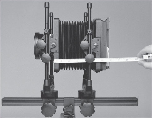
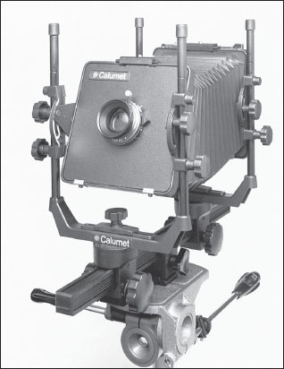
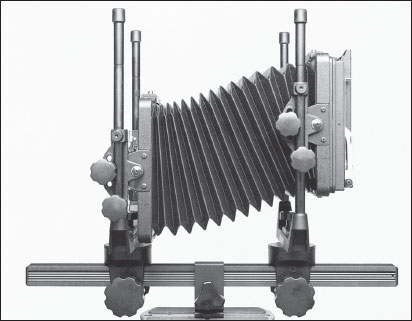
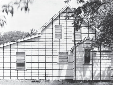
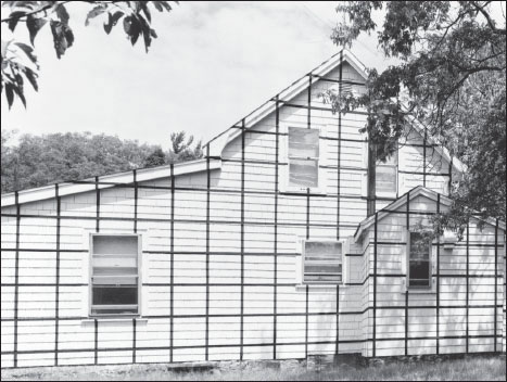
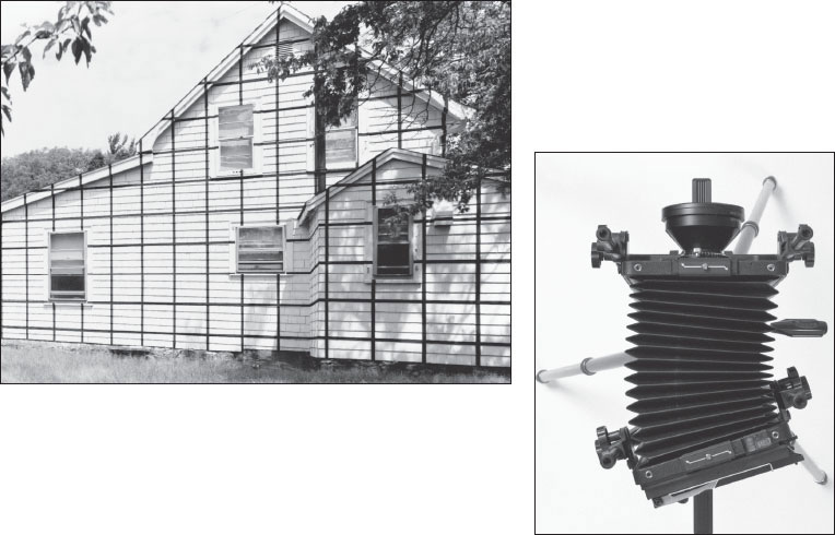
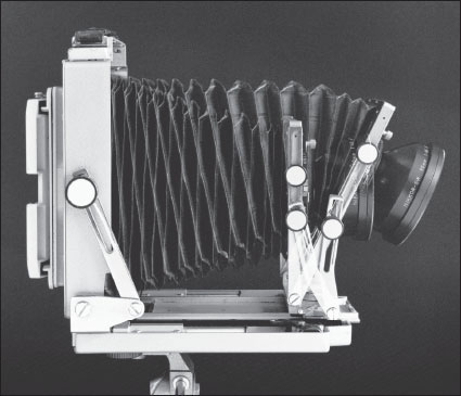
This camera is focused at infinity with its 150mm (6-inch) lens. ■
Compensating for Reciprocity Failure. Accurate compensation tables for each different film’s reciprocity characteristics are available from the manufacturer in their published literature and on their website, and are sometimes packaged with the film. Since the degree of reciprocity failure depends on how much light actually gets to the film, you must consider light losses such as filter factors and bellows extension before figuring reciprocity compensation. Calculating bellows extension, for example, after reciprocity failure compensation will result in underexposure.
In the absence of reciprocity tables, use the following as a rough guide for exposures on black-and-white film. With a metered exposure near 1 second, your film loses half its speed from reciprocity failure and needs one stop more exposure. At an exposure of about 10 seconds, it loses half its speed once again, needing two extra stops. At 100 seconds, film speed is one-eighth normal and needs three extra stops. These exposure compensations must be added to your measured exposures or your film will be underexposed. To compensate for the increased contrast that also results from such long exposures, reduce your development time by 10 percent, 20 percent, and 30 percent respectively for the three examples above. These exposure compensations are accurate when increasing the aperture. Giving the film extra exposure time will require slightly more compensation because the film’s speed continues to diminish with extended exposure. Three extra stops for a 100-second exposure, which with a constant exposure index would total 800 seconds, should actually be 1200 seconds.
Color film is affected by reciprocity failure more severely than black-and-white film. Not only does the film speed change for long and very short exposures, but it changes a different amount for each of the three color-sensitive layers comprising color film. So reciprocity failure brings a color shift that in many cases cannot be corrected by filtration. Film manufacturers made professional color films for different exposure ranges; if available, films balanced for 3200°K (tungsten) light may be used with long exposures with no correction for reciprocity.
Exposures shorter than 1/1000 second occur so infrequently for the large-format photographer that you probably needn’t be concerned with reciprocity failure in that exposure range. Large professional strobe lighting equipment usually produces light bursts of longer duration and the leaf shutters commonly used with large-format lenses rarely have speeds exceeding 1/500 second. If you do encounter very short duration exposures, take the time to test for reciprocity failure with the materials you plan to use before making any important photographs.
You can test your final calculations for exposure, including bellows extension and reciprocity failure, with a sheet of instant film (p. 146). But it is a good practice, and an economical one, to avoid using instant-picture tests in place of calculation.
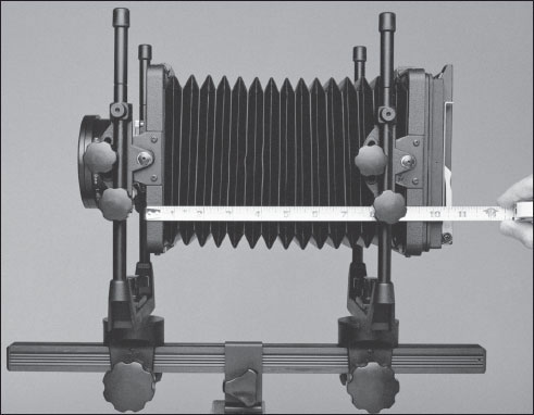
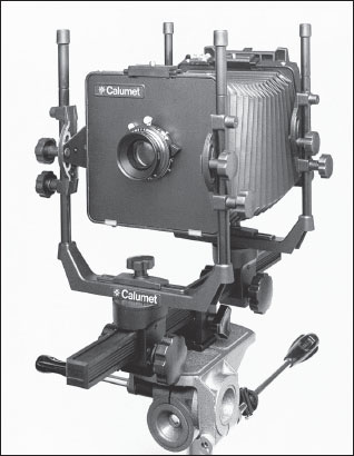
When the camera is focused on a close object, the bellows extension is 10 inches. The formula for bellows extension factor (BEF) is:
![]()
The factor is 100/36, or about 3. The compensation should be made either by multiplying the exposure time by 3 or by increasing the aperture by about 1½ stops. ■