
Quality Control
Industrial processing of adhesives has made considerable progress from the crude processes of the past. Unfortunately, one of the disadvantages of adhesive bonding as an assembly method is that a bond area cannot be inspected visually. Inspection must be carried out by two methods: destructive and nondestructive. Destructive inspection may be carried out on process-control test specimens prepared from the same adherend and adhesive materials as used for the production parts. The process-control specimen, as the name implies, accompanies the production parts throughout the stages of cleaning, assembly, and cure. The adhesives and adherends are all assembled at the same time and cured in the same press or autoclave.
Keywords
Adhesives; process control; TIRI; SAM; bonding
13.1 Introduction
Industrial processing of adhesives has made considerable progress from the crude processes of the past [1]. Unfortunately, one of the disadvantages of adhesive bonding as an assembly method is that a bond area cannot be inspected visually. Inspection must be carried out by two methods: destructive and nondestructive. Destructive inspection may be carried out on process-control test specimens prepared from the same adherend and adhesive materials as used for the production parts. The process-control specimen, as the name implies, accompanies the production parts throughout the stages of cleaning, assembly, and cure. The adhesives and adherends are all assembled at the same time and cured in the same press or autoclave.
As an additional control, each part may be designed with an expendable tab as an integral part of the assembly. After the cure, the tab is removed and subjected to the same tests as the control test specimens. The results are checked against the specification requirements and the part is accepted or rejected based on these results. The rejected parts may subsequently be inspected nondestructively for final acceptance or rejection. Final rejection would result in systematic destruction to learn how good or bad the parts really were. In initial production of critical parts, such as primary bonded structures for aircraft, where human lives are dependent on reliability, a sampling and destructive analysis of actual production parts may be included in the test program [2].
A flow chart of a quality control system for a major aircraft manufacturer is shown in Figure 13.1. This system is designed to detect substandard bonds before they are shipped and to recommend methods of correcting the causes. It combines nondestructive Fokker tests of individual joints with rigid controls over process operations, and destructive tests of sample bonded parts and test specimens. The level of quality control applied to a particular bonded assembly depends on its structural requirements. Critical joints are controlled by high sampling levels for destructive testing and by tight acceptance requirements. Less critical bonds are controlled by less stringent procedures [3].
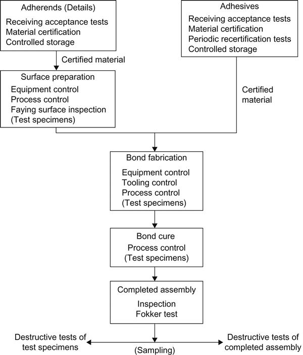
The first phase of the quality control system outlined in Figure 13.1 controls the quality of adhesive material and adherend details making up the joint. Inspections and tests are performed on incoming materials to assure their meeting acceptance requirements. Shortly before use, destructive tests (in which the test specimens are damaged) are conducted on specimens bonded with each batch of adhesive to be used, to insure their capability of developing bond strength after proper cure. The use of carefully controlled storage conditions insures that only certified adherend details and adhesive materials are used in each joint [3].
Rigid process controls insure that each batch of bonded joints receives proper processing during the surface preparation, fabrication, and cure processes. Surface preparation processes are controlled with respect to temperature and composition of baths and immersion time of parts, which is followed by inspection of treated faying surfaces to determine wettability. Fabrication operations are regulated by process controls in conjunction with tests and controls over dimensions, alignment, and pressurization provided by the tooling. Cure conditions are generally controlled by incorporating thermocouples into the bondline to monitor actual cure temperature and time. Although these rigid controls do not completely assure proper processing, there is a high level of assurance that each batch of parts is processed to develop acceptable bond quality in the lot [3].
Test coupons, or preferably extensions of the actual parts (i.e., tabs), pass through the entire bonding process with the particular lot of assemblies they represent. These specimens are destructively tested in shear, tension, or peel, and the strength of each joint within the lot is assumed to be that of the accompanying test specimens. Test specimens with substandard bond strength cause rejection of the entire lot. In addition, destructive tests are conducted to qualify the first article produced, and subsequently, on a sampling of assemblies produced from each piece of tooling during the production run, to insure that the process and tooling remain under control. These process-control and sampling methods are capable of detecting discrepancies affecting the entire lot of assemblies, but cannot evaluate factors affecting individual joints or specific areas of a particular joint [3].
Incorporating the nondestructive Fokker Test method into the inspection and testing system makes it possible to evaluate many of the factors affecting the bond strength of individual joints. The major limitation of existing quality control systems for adhesive bonding is lack of ability to detect weak bonds caused by local areas of poor adhesion. The major causes of such discrepancies are inadequate surface preparation in particular areas, nonhomogeneous adherend surfaces, or contamination of prepared adherend surfaces or adhesive material during processing. Process controls are incapable of controlling these factors, and existing nondestructive test methods are incapable of detecting weak bonds caused by such discrepancies. The incidence of substandard bonds can be decreased by rigid controls over materials and processes, and by particular care being taken by production personnel. These methods are not capable of providing complete assurance of high-quality bonds, however. The solution to this problem would be the development of a nondestructive test method capable of measuring the properties of adhesive–adherend interfaces and the adhesion of films to adherend surfaces. Until such a nondestructive test method is developed, the present combination of rigid process controls, destructive tests of specimens, and nondestructive tests of each completed joint will remain the most reliable means of assuring the quality of adhesive bonds and bonded structures [3,4].
13.2 Incoming Material Control
Quality control begins on the receipt of raw materials such as adhesives and catalysts. The purchase order ordinarily defines the required quality properties of this material. This is accomplished by an actual statement of requirements or by what is called out in the material specifications. The inspection requirements are normally specified in the material specifications as Quality Acceptance Tests or as Receiving Inspection Requirements [5].
Containers: The first inspection requirement is normally the condition of the container. The following items should be checked when inspecting the container [5].
Damage: Physical damage to a container of film adhesive can rupture its sealed wrapper, allowing moisture, dirt, etc., to reach and contaminate the adhesive. Damage can render a pail of liquid measure unusable in automatic measuring equipment.
Leakage: Leakage of liquid adhesive components can change the ratio of the catalyst to the base resin if premeasured kits are involved. It can also result in the receipt of less material than the purchaser needs and is paying for.
Identification: Identification of a container should include:
13.2.1 Adhesives
Incoming adhesive material control includes two types of tests, physical properties, such as percent flow, gel time, and percent volatiles, which are of interest to the process engineer in assuring the quality of the bond. An example is the test for percent flow. This test is of value in maintaining the bonding process so that the adhesive flow is not be too high, which could cause an adhesive-starved bond. Too little flow, on the other hand, would cause a thick or inadequately filled bond [6]. Test methods used for physical properties include the following:
ASTM methods for testing physical properties include: D816, D898, D899, D1084, D1337, D1489, D1490, D1579, D1582, D1583, D1875, D1916, D2556, D2979, D3121, and D3236.
Federal Test Method Standard No. 175B for physical properties: Methods 4032.1, 4041.1, and 4051.1.
13.2.1.1 Adhesives: Mechanical Properties
The mechanical properties of incoming adhesive materials are of interest since they are indicative of the structural results to be obtained in the final bonded assembly. The various tests and requirements for mechanical strength properties of structural adhesives are described in various specifications and test methods described in Chapter 12. Some of the test methods covering mechanical strength properties, including durability, flexibility, and fatigue are as follows:
ASTM methods for measuring the mechanical properties of adhesive bonds include: ASTM D897, D903, D905, D906, D950, D1002, D1062, D1144, D1184, D1781, D1876, D2095, D2295, D2339, D2557, D2918, D2919, D3111, D3163, D3164, D3165, D3166, D3167, D3528, D3808, D3931, and D4027.
Federal Test Method Standard No. 175B for mechanical properties: Method 1081.
13.2.1.2 Adhesives: Miscellaneous Properties (Including Creep)
13.2.2 Surface Preparation Control
The second step, after determining the quality of incoming materials, is adherend surface preparation [7]. Surface preparation must be carefully controlled for reliable production of adhesive-bonded parts. If a chemical surface treatment in required, the process must be monitored for proper sequence, bath temperature, solution concentration, and contaminants. If sand- or grit-blasting is employed, the abrasive must be changed regularly.
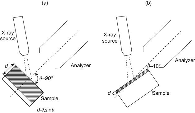
Fresh solvents for cleaning should be on hand. Checks should be made to determine if cloths or solvent containers have become contaminated. The specific surface preparation used can be checked for effectiveness by the water-break-free test. After the final treatment step, the substrate surface is checked for its ability to form a continuous film of water when deionized water droplets are applied to the surface. Care must be taken in the assessment of surface preparation because of the dependence of results on the test method. Figure 13.2 illustrates the dependence of the sampling depth on the angle of sample tilt (incidence angle of X-rays) in X-ray photoelectron microscopy, also known as electron spectroscopy for chemical analysis (ESCA).
After the surface treatment has been found to be adequate, precautions must be taken to assure that the substrates are kept clean and dry until the bonding operation. The adhesive or primer should be applied to the treated surface as quickly as possible.
13.2.3 Process Control of Bonding
In addition to surface preparation of the adherends described earlier, the production of adhesive-bonded parts involves: (i) prefit, (ii) adhesive application, (iii) assembly, and (iv) cure.
13.2.3.1 Prefit
All detail parts must be dry-fitted together to insure a close contact of the faying surfaces. If two or more detail parts do not fit prior to being bonded, they are not likely to fit well enough after being bonded to produce a good joint. If a high production rate exists where a reproducible fit accuracy can be established, the prefit can sometimes be omitted. First article fits can be checked using tool-proofing films that produce an imprint or image of the joint fit. This can greatly reduce the risk factor of poor fit where expensive or critical components are involved. After prefit conditions are verified, each detail part fitted in that assembly should be identified as such to facilitate mating of those specific parts after adhesive application. Process-control test panels or excess tag-end portions of the assembly should be included with the kit or prefitted details at this point and verified at the time of prefit inspection. These process-control test specimens must be processed through all operations simultaneously with the end product. They should be tested after curing to verify the adhesive batch, surface preparation, and other processing conditions used on that end item [5].
13.2.3.2 Adhesive Application
Most structural film adhesives require a primer. Adhesive primers are usually spray-applied by air or airless spray systems. Roller or brush application is sometimes used in small areas, or where spray equipment is not available. The primer coat must be air-dried and sometimes over-baked to remove solvents. The thickness of the prime coat will usually affect the adhesive bond strength and must be controlled and verified. This is usually accomplished by periodically certifying the primer applicator, and by monitoring primer thickness after drying [5].
Film adhesives are applied by removing a paper or plastic separator/protective film and laying the adhesive on the facing surface smoothly, taking care not to allow wrinkles to develop, or air to become entrapped between the adhesive and the substrate surface. A common workmanship error is failure to remove the separator film before assembly of the detail parts. Some bonders utilize special check-off points to insure its removal. The batch number, lot number, time and date of application, and adhesive type should be logged into the inspection record for traceability should a failure occur. The shop-life expiration date and time should also be logged to aid in controlling assembly and cure of the adhesive [5].
13.2.3.3 Assembly
The adhesive-coated detail parts are usually joined in a tool or holding fixture. Cleanliness and proper preparation of the tools should be verified. Time limits on the surface preparation, shop life of the adhesive, and remaining time during which the adhesive must be cured need verification at the point of assembly.
Assembly of detail parts in their proper sequence and fit should be verified. Maintenance of cleanliness and atmospheric control is important. The atmosphere to which the parts and the adhesive are exposed must be controlled from the time the detail parts are prepared for adhesive application until the cure is initiated. The atmosphere is usually controlled by the following steps: (i) keeping the temperature between 18°C and 32°C, (ii) keeping relative humidity between 20% and 65%, (iii) filtering of all incoming air to preclude air-borne contaminants, and (iv) maintaining a slight positive pressure differential between the controlled environment area and all surrounding areas. Temperature and humidity indicators of the recording type should be used to verify the conditions [5].
13.2.3.4 Curing
Curing an adhesive in any joint is usually a time–temperature–pressure function. No matter how these three variables are controlled, the documentation verification means are essentially the same. Controlling the length of cure time can be by manual or automatic timing devices. Verification is usually documented on a cure chart taken from a temperature and/or pressure recorder. Recording of pressure and temperature is made in the same manner [5].
The heat source must be certified for its basic capabilities and uniformity with respect to its intended use. The following factors must be considered: (i) heat-up rate, (ii) maximum temperature limits, (iii) temperature range or spread during heat-up and at cure temperatures, and (iv) cool-down characteristics. The same degree of verification (namely certification) is required for the pressure characteristics of the facility, whether it is an autoclave, a vacuum system, or a press [5].
13.2.3.5 Standard Test Specimen
It is very desirable to fabricate a standard test specimen in the same cycle pertaining to the part being bonded. This specimen should be designed for a test method that is indicative of the prime structural loading requirement. For example, if the critical item is normally loaded in tensile shear, the specimen should be of the lap-shear type.
13.3 Final Inspection
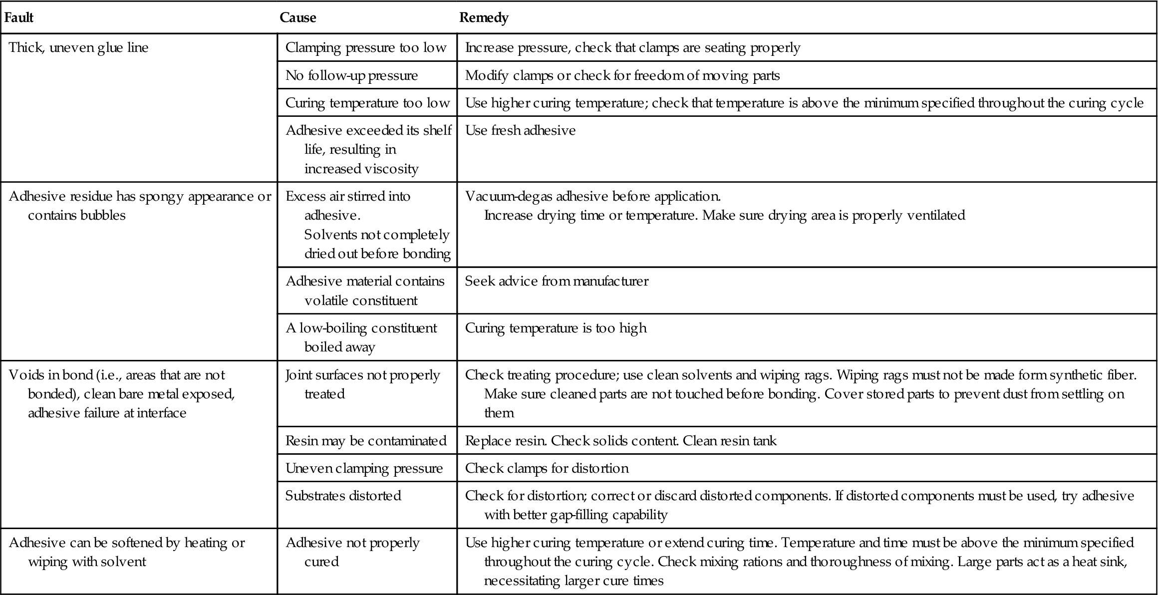
After the adhesive is cured, the joint area can be inspected to detect gross flaws or defects. This inspection procedure can be either destructive or nondestructive, as discussed in Section 13.1. Destructive testing generally involves placing samples of the production run in simulated or accelerated service and determining if it has properties similar to a specimen that is known to have a good bond and adequate service performance. The causes and remedies for a number of faults revealed by such mechanical tests are described in Table 13.1. Destructive (mechanical) tests that can be carried out on adhesive bonds are listed in Section 13.2.1.1 (Adhesives: mechanical properties). Nondestructive tests are far more economical, and many more assemblies can be tested.
Table 13.1
Defects in Adhesive-Bonded Joints Revealed by Mechanical Tests [9,10]
| Fault | Cause | Remedy |
| Thick, uneven glue line | Clamping pressure too low | Increase pressure, check that clamps are seating properly |
| No follow-up pressure | Modify clamps or check for freedom of moving parts | |
| Curing temperature too low | Use higher curing temperature; check that temperature is above the minimum specified throughout the curing cycle | |
| Adhesive exceeded its shelf life, resulting in increased viscosity | Use fresh adhesive | |
| Adhesive residue has spongy appearance or contains bubbles | Excess air stirred into adhesive. Solvents not completely dried out before bonding |
Vacuum-degas adhesive before application. Increase drying time or temperature. Make sure drying area is properly ventilated |
| Adhesive material contains volatile constituent | Seek advice from manufacturer | |
| A low-boiling constituent boiled away | Curing temperature is too high | |
| Voids in bond (i.e., areas that are not bonded), clean bare metal exposed, adhesive failure at interface | Joint surfaces not properly treated | Check treating procedure; use clean solvents and wiping rags. Wiping rags must not be made form synthetic fiber. Make sure cleaned parts are not touched before bonding. Cover stored parts to prevent dust from settling on them |
| Resin may be contaminated | Replace resin. Check solids content. Clean resin tank | |
| Uneven clamping pressure | Check clamps for distortion | |
| Substrates distorted | Check for distortion; correct or discard distorted components. If distorted components must be used, try adhesive with better gap-filling capability | |
| Adhesive can be softened by heating or wiping with solvent | Adhesive not properly cured | Use higher curing temperature or extend curing time. Temperature and time must be above the minimum specified throughout the curing cycle. Check mixing rations and thoroughness of mixing. Large parts act as a heat sink, necessitating larger cure times |
13.4 Nondestructive Tests
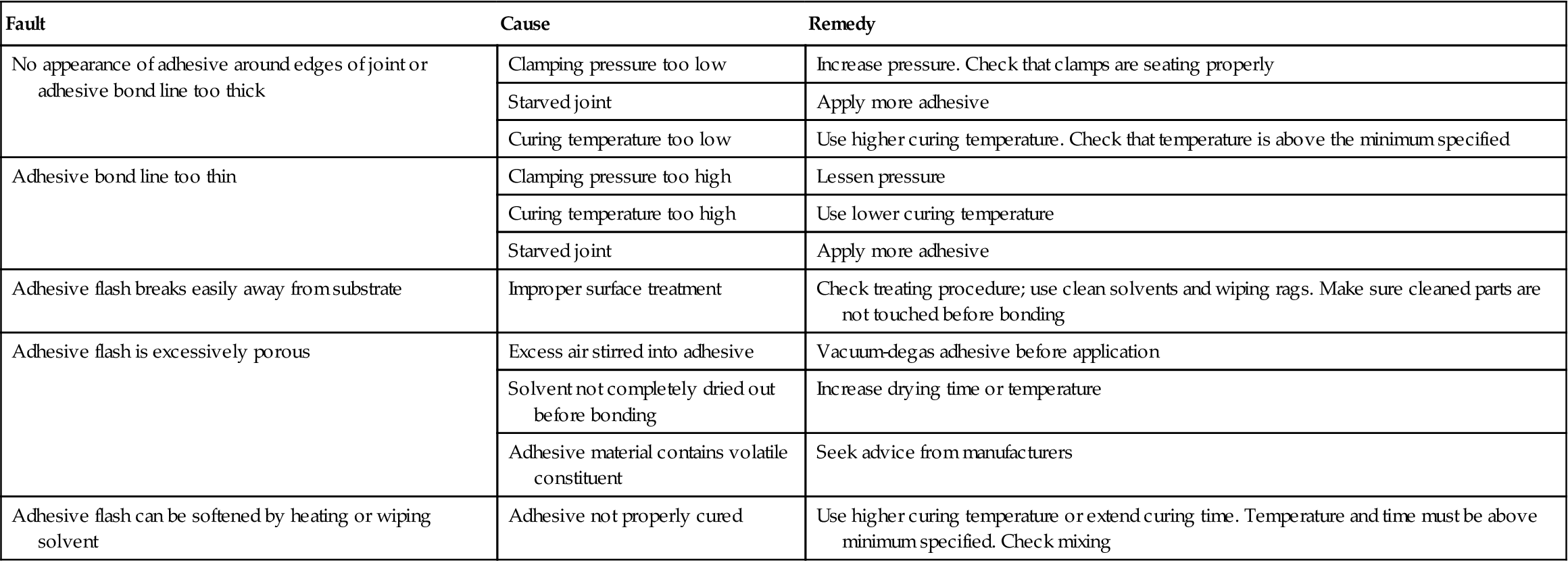
Visual inspection: Visual inspection, with the help of a strong light, can be used to detect gross flaws and defects. Table 13.2 lists the characteristics of faulty joints that can be detected visually. The most difficult to detect by any means are those defects related to improper curing and surface treatments. For this reason, great care and control must be given to surface preparation procedures and shop cleanliness.
Table 13.2
Defects in Adhesive-Bonded Joints Revealed by Visual Inspection [9,10]
| Fault | Cause | Remedy |
| No appearance of adhesive around edges of joint or adhesive bond line too thick | Clamping pressure too low | Increase pressure. Check that clamps are seating properly |
| Starved joint | Apply more adhesive | |
| Curing temperature too low | Use higher curing temperature. Check that temperature is above the minimum specified | |
| Adhesive bond line too thin | Clamping pressure too high | Lessen pressure |
| Curing temperature too high | Use lower curing temperature | |
| Starved joint | Apply more adhesive | |
| Adhesive flash breaks easily away from substrate | Improper surface treatment | Check treating procedure; use clean solvents and wiping rags. Make sure cleaned parts are not touched before bonding |
| Adhesive flash is excessively porous | Excess air stirred into adhesive | Vacuum-degas adhesive before application |
| Solvent not completely dried out before bonding | Increase drying time or temperature | |
| Adhesive material contains volatile constituent | Seek advice from manufacturers | |
| Adhesive flash can be softened by heating or wiping solvent | Adhesive not properly cured | Use higher curing temperature or extend curing time. Temperature and time must be above minimum specified. Check mixing |
13.4.1 Sonic Methods
Tap test: In this method, a coin is used as a special tapping hammer. Tone differences indicate inconsistencies in the bonded joint. Sharp, clear tones indicate that the adhesive is present and adhering to the substrate to some degree. Dull, hollow tones indicate a void or unattached area. Some improvement in the tap test can be achieved using a solenoid-operated hammer with a microphone pickup. The resulting electrical signal can be analyzed on the basis of amplitude and frequency [5,9].
13.4.1.1 Sonic Resonator
This method uses a vibrating crystal to excite a structure acoustically at sonic frequencies (5–28 kHz). The elastic properties of the structure are changed by unbonds or other structural defects. Resulting changes in the crystal loading are processed electronically to obtain an electrical signal for display or recording. The technique can be used to test bonded honeycomb structure without regard to the material of either the facing sheet or the honeycomb core. The method requires comparison standards and a liquid for coupling the probe to the specimen. The apparatus used is capable of detecting unbonds, crushed core, and water content [11].
13.4.1.2 Eddy-Sonic Test Method
This method is based on the principle that a mechanical force is inherently associated with flow of eddy currents. Since the eddy current field is time variant, the mechanical force is also time variant. Therefore, an acoustic vibration can be induced in the proper sample. To use this principle in nondestructive testing of honeycomb materials, some constituents must be electrically conduit.
The major advantage of the method is that no liquid energy compliant is needed, because air serves as a satisfactory coupling medium. The eddy-sonic method is useful for detecting both near-side and far-side unbonds in thin honeycomb structures. It can also be used to detect crushed core, fractured core, and voids in the adhesive.
13.4.1.3 Pulsed Eddy-Sonic Test Method (Shurtronic Harmonic Bond Tester)
This method can detect both near-side and far-side unbonds in many types of honeycomb and laminar structures. It can also detect crushed core, fractured core, and excessive buildup in repaired structures. At least one of the surfaces must be electrically conductive to some extent [11].
13.4.1.4 Arvin Acoustic Analysis System
This is an indicator system that produces and detects acoustical vibrations in metal surfaces. It is useful for bond inspection of aluminum honeycomb materials. No acoustic coupling is required.
13.4.2 Ultrasonic Methods [12–15]
These methods are based on the response of the bonded joint to loading by low-power ultrasonic energy [2]. Ultrasonic methods are especially useful in detecting unbonds of the following types [11]:
1. Unbonds between the facing sheet to adhesive interfaces in honeycomb structures.
2. Unbonds between the adhesive-to-core interfaces in honeycomb structures.
3. Unbonds between adherends in adhesive-bonded laminate structures.
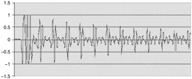
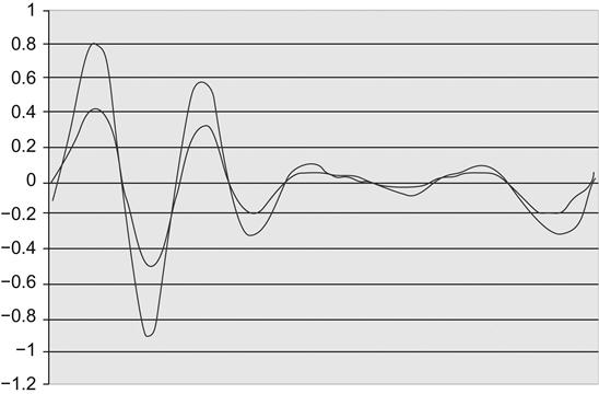
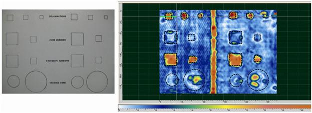
Improvements in analysis and interpretation of ultrasound signals have improved their utility as a diagnostic technique for examination of adhesive bonds. For example, in a metallic adhesive bond, the collected output in shown in Figure 13.3. The signals usually have a repetitive nature as the signal reverberates in the steel plate. Signals from the defective or “bad” bonds are different to those from the “good” bonds as they vary in signal amplitude (Figure 13.4). Combining the results from each location on a grid, produces a C-scan with the lighter areas indicating defective areas of bonding (Figure 13.5). Three “good” and three “bad” bond locations, with varying degree of defectiveness, were chosen for analysis.
13.4.2.1 Ultrasonic Pulse Echo Contact Impedance Testing
The contact impedance technique is based on the fact that when a vibrating crystal is placed in a composite structure (Figure 13.6), the characteristic impedance or elastic properties of the structure determine the manner in which it is loaded. Changes in loading will change the amplitude or phase of the crystal with respect to the applied voltage. These changes can be indicated by suitable meter readout or can be displayed on a cathode-ray tube. The pulse echo technique can be evaluated by observing energy reflection from defects and from the back surface of the structure being inspected. Both these methods are useful in detecting unbonds in honeycomb and laminar structures. They are also capable of detecting crushed core, fractured core, and adhesive buildup in repair areas. The response of these methods to a completely unbonded area in a honeycomb panel is difficult to differentiate from that with some other anomaly. Water, for example, shows the same response as no bond [11].
13.4.2.2 Ultrasonic Pulse Echo Immersion
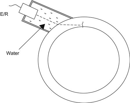
To improve the energy transfer from the transducer to the test object, a coupling (liquid, generally) medium between them is used (Figure 13.7). Water is the most common fluid used for immersion coupling, because of its availability and low cost. This technique can be applied when the surface of the test object is very rough or it has a complex curved geometry that requires the use of a special set of shoes for the transducer.
13.4.2.3 Ultrasonic Multiple Transducer
Through-transmission techniques use two aligned transducers located in opposite sides of the part. One transducer acts as transmitter and the other as receiver. The transducers can be in contact or immersed.
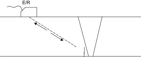
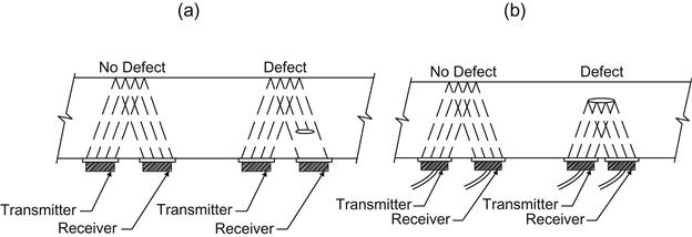
The pitch and catch technique is a test with a transmitter and a receiver transducer where the path of the ultrasonic beam is not straight line but follows a complex path (the beam is reflected one or more times before reaching the receiver). Different configurations can be distinguished: direct pitch and catch, in which the receiver is placed where the reflected ultrasonic beam is expected if there is no discontinuity; and indirect pitch and catch, in which the receiver is placed where the ultrasonic beam is expected to be if reflected by a discontinuity (Figure 13.8). The tandem method is a typical example of direct pitch and catch test. Delta testing is an example of an indirect pitch and catch test.
The time of flight diffraction technique is a hybrid of the direct and indirect pitch and catch tests. Ultrasonic waves from a transmitter probe are diffracted from the tips of a crack as well as transmitted along the scanning surface and reflected from the back wall.
The diffraction patterns are separated in space so their reception by the receiving transducer is separated by time. This difference in time can be used to locate and size the crack.
Use of a dual element transducer is an extended example of multiple probe technique in which one element acts as emitter and the other as receiver. These transducers are designed for measuring very thin materials or when detecting near surface discontinuities. Using this concept, it is possible to focus the ultrasonic beam. One of the major uses of focused probes is defect sizing by means of diffraction techniques.
A phased array transducer is an arrangement of transducer elements properly excited that allow the shaping and control of the ultrasonic beam in a specific manner. Beam steering is achieved by sequencing the transmission and reception of elements to steer the ultrasonic beam. The firing of array elements can be controlled to form an overall wave front, providing dynamic focusing. This wave front can be controlled (shaped) by firing the outermost elements first and then firing the elements toward the interior of the transducer.
13.4.3 Sweep-Frequency Resonance Method
This method has the advantage of producing a quantitative estimate of bond strength in metal-to-metal and metal-to-core structures, as well as similar structures made from nonmetallic materials [30]. Energy is introduced into the structure and varied over a wide temperature range; the resonance set up by the probe, face sheet, adhesive, and the remainder of the structure is observed [5]. The principle is as follows: when a crystal resonating at its natural frequency is placed on a composite structure, the characteristic impedance or elastic properties of the structure determine the manner in which it is loaded. Changes in loading are shown by the combination of the two instrument readings—resonance frequency shift and a change in amplitude of the resonant frequency. Such a change is indicated by meter readout and displayed on a cathode-ray tube. Light oil is used as a coupling medium.
The Fokker Bond Tester has been used successfully in determining near-side unbonds in a wide variety of adhesively bonded structures. It does not give good results in detecting unbonds in honeycomb panels with laminated facing sheets. In addition to unbonds, it is capable of detecting crushed core, fractured core, and voids in the adhesives [11]. The Fokker Bond Tester is most sensitive to properties which physically affect adhesion, such as voids, porosity, and incomplete wetting. It is not capable of detecting incomplete cure, poor surface preparation, or contamination of the interface [9].
13.4.4 Liquid Crystals
Cholesteric liquid crystals are compounds that go through a transition phase in which they flow like a liquid, yet retain much of the molecular order of a crystalline solid. Liquid crystals are able to reflect iridescent colors, depending on the temperature of their environment. Because of this property they may be applied to the surfaces of bonded assemblies and used to project a visual color picture of minute thermal gradients associated with bond discontinuities. Cholesteric crystals are potentially a simple, reliable, and economical method for evaluating bond defects in metallic composite structures [11]. Materials with poor heat-transfer properties are difficult to test by this method. The joint must also be accessible from both sides [31].
13.4.5 Holography
Holography is a method of producing photographic images of flaws and voids using coherent light such as that produced by a laser. The major advantages of this method are that it photographs successive “slices” through the scene volume, thereby making it possible to reconstruct a three-dimensional image of a defect or void [32]. It is possible, using stored-beam holographic techniques, to make real-time differential interferometric measurements to a precision of the order of one millionth of a centimeter on ordinary surfaces. A simple method of inspecting bonded panels is to place them horizontally and to apply a thin layer of sand in the top surface. On vibration of the panel, any unbonded areas will be revealed by the pattern resulting from the movement of the sand particles. Bond quality can also be determined by making circular cuts through one adherend down to the bondline in a zone where the strength of the assembly will not be affected. The disks are then pried out to expose the adhesive to visual inspection. Plugs may be inserted later in the cutouts. In certain cases, test specimens are treated and bonded simultaneously with production parts under identical conditions. These specimens are then tested for strength [33].
Holographic techniques are very useful in their ability to measure differential displacements. This property of holography makes it a useful tool for detecting nonbonds in laminar structures. When these structures are stressed by any of several means (heat, differential pressure, or mechanical), the displacement of the surface can be related to the integrity of the bonded layers beneath the surface. A laminar material that is well bonded will have a uniform surface displacement, which is a function of the physical properties of the material, the means of stressing, and the holographic technique. If the material has a nonbonded region somewhere in the different layers, then the surface above that region will displace in a different manner than the rest of the surface, due to the change in the boundary conditions. This change in the surface displacement is a microscopic differential change and would not normally be visible. Because of holography’s remarkable sensitivity, such microscopic changes are clearly visible. The means of achieving surface displacements and thereby assessing the integrity of the bonding is called double exposure holography [34].
13.4.6 Thermal Image Inspection
In this method, bond discontinuities are revealed through temperature differences on the assembly surface. Ultraviolet radiation is used to permit direct visual detection of these discontinuities as dark regions in an otherwise bright (fluorescent) surface. For practical purposes, to preclude thermal damage to the adhesive and/or heat-sensitive adherends, a phosphor is used that shows a large change in brightness with a small change in temperature in the near-room-temperature range (25–65°C). The coatings used for this purpose provide a stable (nonsettling) suspension of the phosphor in the vehicle that can be applied by conventional paint spray equipment [33].
13.4.7 Thermal Infrared Inspection (TIRI)
This technique has been used to detect internal voids and unbonded areas in solid-propellant rocket engines and in large, panel-shaped components [33]. The technique uses a dynamic heating principle with continuous injection of thermal energy from an induction generator into the exposed surface of the specimen along a line of scan. Continuous radiometric detection of the emission form contiguous surface regions along the line of scan, gradients at the outer surface. The depth of the flaw below the surface of the material (interface level) is determined by comparison of inspection recordings taken at pre-established exposure times. Destructive sectioning of representative specimens following TIRI examination shows a correlation of 95% for first and second interface defects [35].
13.4.8 Radiography
Radiographic inspection techniques have been used successfully for detecting defects in adhesive-bonded metal-to-metal joints and metal sandwich structures. In the case of metal-to-metal joints, the adhesive must contain some metal powder or other suitable radio-opaque filler to create sufficient contrasts to show up defects. The same procedure can be used with nonmetallic adhesive-bonded joints. An experienced inspector, using radiography, can often detect undesirable concentrations of adhesive, or evaluate the quality of adhesive-bonded structures. Damage can occur in handling or may be the result of unequal pressure during the bonding cycle [5]. Radiography will detect lack of bond areas where the adhesive is present but not bonded to one or both adherends [11].
13.4.9 X-Ray Techniques
These methods may be used only if fillers (as radio-contrast agent) are added to the adhesive. This results form the slight weakening of the rays in penetrating through the unfilled adhesive because of its low density. Excellent results may be obtained by adding lead oxide. In this case, it is possible to detect even the smallest air and gas bubbles. Conventional X-ray equipment for flaw detection is used. Because of the thinness of the adhesive layer, very long rays must be used [33].
13.4.10 Radioisotope Methods
For inspecting the toughness of combined bonded and spot-welded joints radioactive isotopes may be used to check the possibility of electrolyte penetrating to the bondline during subsequent anodizing in sulfuric acid. A radioactive sodium isotope, such as sodium-22, with a half-life of 2.5 years, is introduced into the most active electrolyte. If there are voids in the adhesive layer, the electrolyte penetrates into the clearance between the adherends. The joint is then washed clean and examined with a radiometer. If voids are present, the radioactive substance is retained in them and the radiation intensity is higher. The application of this method in industry is limited, however, because of the danger from radiation [33].
13.4.11 Neutron Radiography
If the adhesive used is not X-ray opaque, neutron radiography may be used. The hydrogen atoms in the adhesive absorb neutrons, making the adhesive radio-opaque [6]. The neutron radiographic technique detects within adhesive bond lines and predicts the lap-shear strength, usually within 5–10%. A portable system permits the method to be applied to aircraft with adhesively bonded parts. Although ultrasonic and X-ray techniques can determine void content and joint strength, neutron radiography appears to have more sensitivity. In addition, it seems to be more nearly independent of metal thickness than X-ray and less dependent on scattering and geometric complexity than the ultrasonic method [35].
13.4.12 Penetrant Inspection
This method is used for local examination of sections of seam joints. The surface of the specimens must first be cleaned and degreased. Then a penetrant solution is applied along the joint. Capillary action pulls the solution into any defect open to the surface. The penetrant on the surface is rinsed with a solvent, leaving the penetrant in the defects. A developer is then applied to draw back the penetrant to the surface. Because the penetrants are brilliantly colored, each defect is easy to see [33].
13.4.13 Scanning Acoustic Microscopy (SAM)
This technique is also known as scanning acoustic tomography [36]. This is a powerful tool for spotting delaminations, cracks, and other anomalies nondestructively. Not only does acoustic microscopy detect the failures but it can also provide the specific location of the problem. SAM high-resolution images and advanced diagnostic tools are used to [37]:
• diagnose device failures and discover failure “root causes”
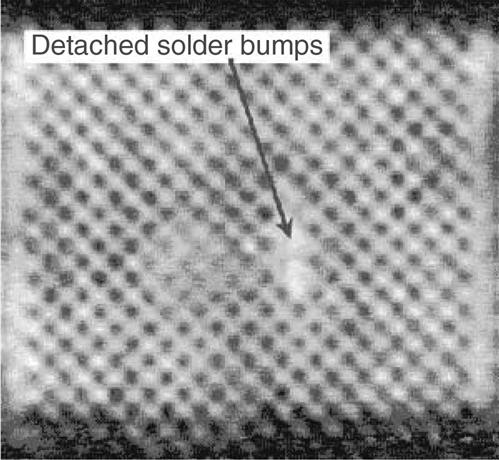
SAM uses acoustic impedance to produce high-resolution images of a sample’s interior structure to detect “difficult-to-find” defects, such as interfacial separation (printed wire boards), solderball delamination, and die attach voiding (Figure 13.9). Both delamination/cracking and die attach voiding are manufacturing and assembly related defects that can increase the susceptibility of components to failure in storage or use, although they do not constitute failures by themselves. Delamination and cracking can result in sheared or lifted wirebonds, passivation cracking, metallization shifting, intermittent electrical failures, and metallization/bondpad corrosion. Die attach voiding can lead to die cracking, die attach fracture, or thermal runaway due to poor heat dissipation through the die attach [38].
13.5 Weldbonding
The extent of process and quality control used in weldbonding (see Chapter 8) must be based on the end use of the hardware being bonded. Methods in current use should be selected to fit a specific application. Consistent joint strength can be assured by evaluating cured weldbond tensile-shear specimens, cleaned with each batch of parts, for strength and bond quality. Consistent weld quality can be assured by hourly evaluation of uncured tensile-shear and macro specimens for strength and weld quality. Even higher assurance can be obtained from the use of an in-process weld monitor that will detect unacceptable welds.
The extent of the inspection of the production item must be determined from or based on, the end use of the part, and will also be affected by the size and complexity of the part. If the parts are small, visual inspections for surface defects and surface adhesive irregularities may be adequate. If the parts are large and complex and the end use is critical, radiographic inspections may be used for determination of weld quality and ultrasonic inspection for determination of bond quality [39]. X-ray radiography will reveal weld nugget defects such as cracking, expulsion, and porosity [40]. Infrared nondestructive methods cannot be used for weldbonded structural assemblies [41]. Process specifications prepared by leading aerospace corporations under government contracts have sections covering quality assurance provisions and should be consulted.