
Material Surface Preparation Techniques
Surface treatment and preparation for adhesive bonding is complicated due to the material-specific nature of the required methods. This chapter describes the surface preparation and treatment techniques in a general way. Readers interested in information about the treatment of specific materials should refer to sources devoted to that topic.
Keywords
Cleaning; priming; sol–gel process; surface exposure time
3.1 Introduction
Surface treatment and preparation for adhesive bonding is complicated due to the material-specific nature of the required methods. This chapter describes the surface preparation and treatment techniques in a general way. Readers interested in information about the treatment of specific materials should refer to sources devoted to that topic [1].
This chapter describes surface preparation metallic and nonmetallic (plastics and elastomers) materials in separate sections. Sections 3.3–3.6 describe the surface treatment techniques of metals. Section 3.7 describes those of plastics and elastomers. Sections 3.8 and 3.9 address methods to assess the effectiveness and age of surface treatment.
3.2 General Considerations
Since adhesive bonding is a surface phenomenon, preparation prior to adhesive bonding is the key to success. Surface preparation (or surface pretreatment) is carried out to render adherend surfaces receptive to the development of strong, durable adhesive joints. It is desirable, although not always practical, to have the basic adherend material exposed directly to the adhesive, with no intervening layer of oxide film, paint, primer, chromate coating, chromate-free coating, phosphate coating, or silicone release agent. Such layers are called weak boundary layers, and in their presence the adhesive never directly contacts the adherend surface [2]. The key to good surface pretreatment of many metallic adherends is to generate stable, controlled oxide growth on their surfaces.
Selection of the exact surface preparation method for a particular adherend requires careful evaluation. A number of factors, some obvious and some not, influence the choice. The size of component parts and the availability of equipment and facilities are obvious considerations. Less obvious factors include the rapid depletion of active chemicals in an immersion bath, or the accumulation of foreign materials in the bath, which give rise to weak boundary layers [2].
To place surface preparation in proper perspective, the interface of adherend-to-organic material (i.e., adhesive) must be considered from design through fabrication. The interdependent factors of joint design, adhesive selection, and processing all must be considered. Optimum surface preparation is of little value if an unsuitable adhesive is used, if the bond is not properly processed, or if the joint design involves peel or cleavage stress [3].
Table 3.1 gives the different surface treatment processes for metallic and nonmetallic substrates in addition to a short description of the effect of the treatment on the material surface.
Table 3.1
Surface Treatment of Materials to Enhance Adhesion
| Substrate | Treatment Method | Effect of Treatment |
| Metals | Degreasing | Cleaning of the surface |
| Metals | Grit blast | Loose material (weak boundary) removal from the surface and increase in contact surface area |
| Metals | Acid etch/liquid pickling | Surface oxidation |
| Metals | Anodizing | Surface oxidation |
| Plastics | Corona treatment | Weak boundary layer removal and surface oxidation |
| Plastics | Flame treatment | Weak boundary layer removal and surface oxidation |
| Plastics | Chemical etching | Weak boundary layer removal and surface oxidation |
| Fluoroplastics | Chemical etching | Surface defluorination and oxidation |
3.3 Surface Treatment of Metals
Preparing the surface of a metallic sample involves multiple steps, all of which are not always applied. It is impossible to obtain a quality adhesive bond without cleaning (and abrading) the metal surface. Metals have high-energy surfaces and absorb oils and other contamination from the atmosphere. These steps are listed (with the frequency of use in parentheses):
1. Cleaning—using a solvent or other chemical. (Always)
2. Removal of loose materials—mechanical (e.g., grit blasting)—also increases contact surface. (Sometimes)
3. Improvement of corrosion resistance. (Almost always)
4. Priming—applying a material to a surface. (Sometimes)
5. Surface hardening—mechanical or chemical—to strengthen the surface. (Occasionally)
Metal surfaces are best cleaned by vapor degreasing, and effective aqueous systems have been developed. This treatment is followed by grit blasting to increase the adhesive contact surface area by roughening the metal surface. Chemical etching removes weakly bonded oxides from the metal surface and forms an oxide that is strongly bonded to the bulk of the part. A useful step is the priming of the part’s surface, which can improve the wettability of the surface and protect it from oxidation.
The optimum surface preparation to provide durability and uniform quality is ordinarily a chemical immersion or spray process. In the case of very large parts, the application is often carried out by the use of reagents in paste form. Low energy surfaces, mainly plastics, require entirely different surface treatments, which often alter the chemical nature of the surfaces.
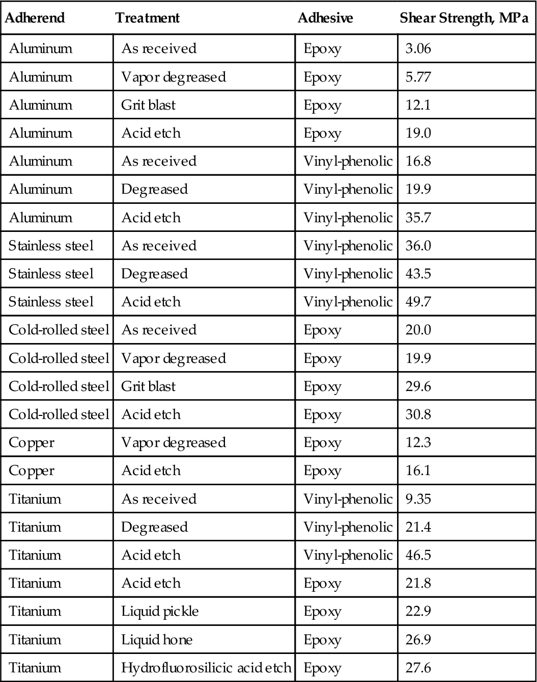
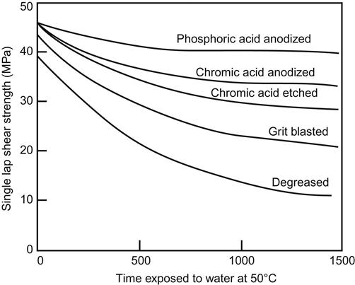
Table 3.2 illustrates the importance of proper surface preparation for five different metal adherends, using two different adhesives and a variety of surface treatment techniques [4]. Figure 3.1 shows how various surface treatments impact the durability of aluminum bonds under adverse conditions. Surface treatment is particularly important for the durability of aluminum. The exact ranking order of the results may change in studies of this type, depending on the adhesive primer and the type of alloy being used [5].
Table 3.2
Effect of Metal Substrate Surface Preparation in Adhesive Bonded Joints [4]
| Adherend | Treatment | Adhesive | Shear Strength, MPa |
| Aluminum | As received | Epoxy | 3.06 |
| Aluminum | Vapor degreased | Epoxy | 5.77 |
| Aluminum | Grit blast | Epoxy | 12.1 |
| Aluminum | Acid etch | Epoxy | 19.0 |
| Aluminum | As received | Vinyl-phenolic | 16.8 |
| Aluminum | Degreased | Vinyl-phenolic | 19.9 |
| Aluminum | Acid etch | Vinyl-phenolic | 35.7 |
| Stainless steel | As received | Vinyl-phenolic | 36.0 |
| Stainless steel | Degreased | Vinyl-phenolic | 43.5 |
| Stainless steel | Acid etch | Vinyl-phenolic | 49.7 |
| Cold-rolled steel | As received | Epoxy | 20.0 |
| Cold-rolled steel | Vapor degreased | Epoxy | 19.9 |
| Cold-rolled steel | Grit blast | Epoxy | 29.6 |
| Cold-rolled steel | Acid etch | Epoxy | 30.8 |
| Copper | Vapor degreased | Epoxy | 12.3 |
| Copper | Acid etch | Epoxy | 16.1 |
| Titanium | As received | Vinyl-phenolic | 9.35 |
| Titanium | Degreased | Vinyl-phenolic | 21.4 |
| Titanium | Acid etch | Vinyl-phenolic | 46.5 |
| Titanium | Acid etch | Epoxy | 21.8 |
| Titanium | Liquid pickle | Epoxy | 22.9 |
| Titanium | Liquid hone | Epoxy | 26.9 |
| Titanium | Hydrofluorosilicic acid etch | Epoxy | 27.6 |
3.4 Cleaning (Degreasing) Metals
Before adhesive bonding, it is essential to thoroughly clean the adherends. Unclean adherends will be unreceptive to optimal adhesion regardless of the quality of materials used, or the stringent control of the application process. Proper surface preparation is extremely important in assuring strong and lasting bonds. For many adherends, surface preparation requirements go far beyond simple cleanliness.
After a cleaning process, removal of obvious surface contamination (such as soil, grease, oil, and finger marks) requiring specific chemical or physical treatments is usually carried out to produce a surface receptive to adhesion. Polytetrafluoroethylene (PTFE) and other fluorinated polymers are good examples of surfaces having this requirement. Adhesion to clean, pure, PTFE is close to zero and it is only after a severe chemical treatment, which alters the surface chemically and physically, that the surface is receptive to adhesion.
Magnesium behaves similarly thus requiring considerable treatment beyond simple cleaning. Strong initial adhesion is possible with clean magnesium. Due to the chemically active nature of the metal, however, the permanency of this adhesion is poor. With many organic materials, such as adhesives, reactions occur at the metal-to-organic material interface, producing by-products having low cohesive properties. These by-products subsequently degrade the initial adhesion to an unacceptable level. For this reason, it is necessary to use chemical or anodic treatments after cleaning magnesium. Such treatments result in the formation of thin inorganic chemical films, which adhere tenaciously to the magnesium, and are at the same time receptive to organic materials such as adhesives. The treatment film laid down in this manner also functions as a barrier between the metal and organic material, preventing any chemical reaction between them. The term “cleaning” has come to mean removal of dirt, contaminants, and oils, and also specific chemical surface treatments for adhesive bonding [3].
3.4.1 General Sequence of Cleaning
Any surface preparation requires completion of one, two, or all three of the following operations [3]:
Priming, discussed in Section 3.5, may also be carried out in some cases to ensure superior durable bonds under particularly adverse environments.
3.4.1.1 Solvent Cleaning
Solvent cleaning is the process of removing soil from a surface with an organic solvent without physically or chemically altering the material being cleaned. This includes methods such as vapor degreasing, spraying, immersion, and mechanical or ultrasonic scrubbing. Solvent cleaning can be an end in itself, as in the case of vapor degreasing of an aluminum honeycomb core before bonding. It may also be a preliminary step in a series of cleaning and chemical treatment operations [3].
The four basic solvent cleaning procedures are [3]:
Vapor Degreasing
Vapor degreasing is a solvent cleaning procedure for the removal of soluble soils, particularly oils, greases, and waxes, as well as chips and particulate matter adhering to the “soil” from a variety of metallic and nonmetallic parts. The principle of vapor degreasing is scrubbing the part with hot solvent vapors. These vapors condense on the part at a sufficient rate to form liquid flow, which dissolves and washes the soil as the condensed solvent drains by gravity. Sometimes it is not possible to wash heavy soil away by vapor degreasing. In such cases, acetone “scrub” is the first step to remove soil followed by vapor degreasing to remove residual oils, greases, etc. Vapor degreasing requires both the proper type of solvent and degreasing equipment. The solvents used must have certain properties, including the following [3]:
1. High solvency of oils, greases, and other soils
2. Nonflammable, nonexplosive, and nonreactive under conditions of use
3. High vapor density compared to air and low rate of diffusion into air to reduce loss
4. Low heat of vaporization and specific heat to maximize condensation and minimize heat consumption
5. Chemical stability and noncorrosiveness
7. Boiling point low enough for easy distillation and high enough for easy condensation (for recycling and reuse of dirty solvent or regeneration of clean solvent from used solvent)
The eight common vapor degreasing solvents have been:
1. Methyl chloroform (1,1,1-trichloroethane)
2. Methylene chloride (dichloromethane)
3. Perchloroethylene (tetrachloroethylene)
6. Trichlorotrifluoroethane-acetone azeotrope
However, 1,1-trichloroethane and methylene chloride have been banned and are no longer used. Alternatives with less deleterious environmental and health impact have been developed, examples of which can be seen in Table 3.3.
Table 3.3
Examples of Environmentally Friendly Vapor Degeasing Solvents
| Trade Name | Composition | Manufacturer |
| Vertrel CMS | Methanol, nitromethane, trans-1,2-dichloroethylene, decafluoropentane, 1,1,1,3,3-pentafluorobutane | DuPont |
| Vertrel SMT | 1,1,1,2,2,3,4,5,5,5-decafluoropentane, trans-dichloroethylene, methanol, nitromethane | DuPont |
| Rho-Tron 225 TM | RHO-CHEM | |
| EnSolv | n-Propyl bromide | Enviro Tech |
| HFE-7100 | Methyl nonafuoroisobutyl ether and methyl nonafluorobutyl ether | 3 M |
| AK-225 T | 3,3-Dichloro-1,1,1,2,2-pentafluoropropane, 1,3-dichloro-1,1,2,2,3-pentafluoropropane, ethanol | Asahi Glass Co. |
| Asahiklin AE3000 | 1,1,2,2-Tetrafluoroethyl-2,2,2-trifluoroethyl ether | Asahi Glass Co. |
| Asahiklin AE3000AT | Trans-1,2-dichloroethylene, 1,1,2,2-tetrafluoroethyl-2,2,2-trifluoroethyl ether | Asahi Glass Co. |
| Asahiklin AE3000ATE | Trans-1,2-dichloroethylene, 1,1,2,2-tetrafluoroethyl-2,2,2-trifluoroethyl ether, ethanol | Asahi Glass Co. |
| Asahiklin AE3100E | 1,2,2-Tetrafluoroethyl-2,2,2-trifluoroethyl ether, ethanol | Asahi Glass Co. |
| Methyl nonafluoroisobutyl ether | Methyl nonafluoroisobutyl ether | 3M Corp |
| Methyl nonafluorobutyl ether | Methyl nonafluorobutyl ether | 3M Corp |
| Asahiklin AK-225 AES | 3,3-Dichloro-1,1,1,2,2-pentafluoropropane, 1,3-dichloro-1,1,2,2,3-pentafluoropropane, ethanol, nitromethane | Techspray |
| EnSolv-GCS | n-Propyl bromide | Enviro Tech |
These materials have a wide range of boiling points, from a low of 39°C for methylene chloride to a high of 121°C for perchloroethylene. Trichloroethylene and perchloroethylene are the solvents most commonly used for vapor degreasing, particularly the former. Considerable detail on the equipment required and the vapor degreasing process is given in Ref. [3]. The discussion of chlorinated solvents is of historical and technical interest because the use of nearly every one of them has been banned. The health, safety, and environmental risks of this class of materials are far too high to justify their use in spite of the excellent results that their application can yield.
Ultrasonic Vapor Degreasing [3]
Vapor degreasers are available with ultrasonic transducers built into the clean solvent rinse tank. The parts are initially cleaned by either the vapor rinse or via immersion in a boiling solvent. They are then immersed for ultrasonic scrubbing, followed by rinsing with vapor or spray plus vapor. During ultrasonic scrubbing, high-frequency inaudible sound waves (over 18,000 cycles per second) are transmitted through the solvent to the part, producing rapid agitation and cavitation. The cavitation (repeated formation and implosion, or collapsing, of the bubbles in the solvent) transmits considerable energy to the parts and any surface contaminants. Particulate materials, insolubles, and strongly adhered soils are quickly removed from a part, even on remote surfaces and blind holes. The ultrasonic frequency and intensity for optimum cleaning must be selected by test. They depend on the type of part being cleaned, soil removed, and particular solvent in the system. Some ultrasonic degreasers have variable frequency and power controls. The most common frequency range for ultrasonic cleaning is from 20,000 to 50,000 cycles per second. Power density may vary widely, but 2, 5, and 10 W/in2 are common.
Ultrasonic Cleaning with Liquid Rinse [3]
Ultrasonic cleaning is a common procedure for high-quality cleaning, utilizing ultrasonic energy to scrub the parts and a liquid solvent to rinse away the residue and loosened particulate matter. This procedure, rather than using the vapor degreasing technique for precleaning and final rinsing, utilizes the manual application of liquid solvents. The process is not limited to any particular solvents; organic solvents need not be used. It is widely applied with aqueous solutions: surfactants, detergents, and alkaline and acid cleaners. The only real limitations are that the cleaning fluid must not attack the cleaning equipment, fluids must not foam excessively, and the fluids must cavitate adequately for efficient cleaning.
The process is not as efficient as vapor rinse, solvent wipe, immersion, or spray, but is suitable for many surface preparation applications and pretreatments. One or a combination of these techniques may be used. A large number of solvents are recommended. Solvent wiping is the most portable and versatile of these methods, but also the least controllable. There is always a danger of incomplete removal of soil, or spreading of soil in a uniform manner, causing its presence not to be readily visible, and contamination of a surface with unclean wiping materials.
For general cleaning, wiping materials should be clean, freshly laundered cotton rags, new cheese cloth, or cellulose tissues. For superclean applications where cleaning must occur in a controlled “clean” room, specially processed lint-free polyurethane foam wiping materials are available (from Sills and Associates, Glendale, CA). The solvent should be used only once, poured onto the wiping material. The wiping material should never be immersed in the solvent. Solvent containers with small openings should be wiped systematically with the solvent-soaked cloth or tissue. The wiping material should be discarded and the surface cleaned again with new solvent and cloth or tissue. This cycle should be repeated until there is no evidence of soil on either the cloth or the cleaned surface.
Although immersion and soaking in a solvent is often sufficient to remove light soil, scrubbing may be required for heavier soils. The most efficient scrubbing method is ultrasonic, discussed above. Other scrubbing techniques include tumbling, solvent agitation, brushing, and wiping. After the parts are soaked and scrubbed, they must be rinsed. The quality of cleaning produced by the immersion process depends primarily on the final rinse. The solvent spray cleaning method is efficient due to the scrubbing effect produced by the impingement of high-speed solvent particles on the surface. The solvent impinges on the surface in sufficient quantity to cause flow and drainage, which washes away the loosened soil. Also, since only clean solvent is added to the surface, and scrubbing and rinsing occur, there is no danger of contamination as there is with the immersion process.
Safety [3]
Four safety factors must be considered in all solvent cleaning operations: toxicity, flammability, hazardous incompatibility, and equipment. The solvents must be handled in a manner preventing toxic exposure of the operator. Where flammable solvents are used, they must be stored, handled, and used in a manner preventing any possibility of ignition. Knowledge of the hazardous incompatibility of the solvents, cleaning equipment, and materials to be cleaned is essential. Safe equipment and proper operation is also critical. Snogren [3] lists maximum acceptable concentrations (MACs), a term synonymous with threshold limit values (TLVs) for a number of solvents used in cleaning. These values are given in parts per million (ppm). Examples are acetone—1000 ppm; methyl alcohol—200 ppm; and methyl chloroform—500 ppm. Obviously methyl alcohol, which requires less concentration to incapacitate than methyl chloroform or acetone, is the solvent with the greatest exposure danger. It should be pointed out that TLVs are merely guides in the control of health hazards and represent conditions under which it is believed that nearly all workers may be repeatedly exposed, day after day, without adverse effect.
All flammable solvents should be stored in metal containers, such as safety cans, and must be applied using metal containers. The container should be grounded during pouring or dispensing. Snogren gives flammability limits in terms of percent by volume in air (lower and upper) for the solvents commonly used. Some of the solvents he lists are nonflammable. The flammable solvents must be used only in ventilated areas to prevent accumulation of vapors and fumes. Other obvious precautions must also be taken. Unstabilized methyl chloroform, trichloroethylene, and perchloroethylene are subject to chemical reaction on contact with oxygen or moisture to form acid by-products. These acids are highly corrosive to metals; therefore, only stabilized grades of these solvents should be used. Strong alkalis such as caustic soda may react with trichloroethylene to form explosive mixtures (dichloroacetylene). Fluorocarbon solvents may react violently with highly reactive alkaline earth metals [3].
3.4.1.2 Intermediate Cleaning [3]
Intermediate cleaning is the process of removing soil from a surface by physical, mechanical, or chemical means without altering the material chemically. Small amounts of parent material may be removed in this process. Examples include grit blasting (the most common technique), wire brushing, sanding, abrasive scrubbing, and alkaline or detergent cleaning. Solvent cleaning should always be carried out before this step. Intermediate cleaning operations may be an end in themselves. Examples of such a situation include cleaning stainless steel with uninhibited alkaline cleaner, or detergent scrubbing of epoxy laminates.
Grit Blasting (Contributed by Dr. Laurence W. McKeen)
Grit blasting is the method most commonly used to obtain satisfactory adhesion of fluoropolymer coatings. Grit blasting should precede preheating of ferrous metals to retain the protective oxide formed. With other clean substrates, the order of these two operations is not important.
Grit blasting is a relatively simple process. Hard grit is propelled by compressed air, or occasionally by high-pressure water, at the substrate needing cleaning or roughening.
Grit blast profiles are commonly measured in microinches or root mean square (RMS) by means of a profilometer. A profilometer drags a diamond stylus across the substrate and measures the depth of the peaks and valleys.
Surface profiles in excess of 100 microinches (2.5 µm) are recommended and 200–250 microinches (5.1–6.5 µm) are frequently employed. On hard substrates, aluminum oxide grit from #40 to #80 is commonly used at air pressures ranging from 80 to 100 psi (5.8 to 7.3 kg/cm2) at the gun. Aluminum and brass are commonly used at air pressures ranging from 80 to 100 psi (5.8 to 7.3 kg/cm2) or below. Maximum air pressures on stainless steel may exceed 100 psi (7.3 kg/cm2).
It should be noted that profiles measured by common profilometers indicate only depth of profile. They do not measure uniformity or coverage of the grit, nor the sharpness of the peaks. Full coverage of the grit blast is indicated by lack of gloss on the metal surface when viewed at a flat grazing angle.
There are numerous types of grit. The choice of which grit to use depends upon its intended purpose, the substrate, and the expense. Hardness is an important property of the grit (grit needs to be harder than the substrate to roughen it). Denser materials have more momentum and impart more energy to the substrate.
Sometimes minimal damage to the substrate is required. This could be due to the relative softness of the substrate, or because the texture of the substrate or pattern machined in the substrate needs to be maintained. Plastic grit, walnut shells, or sodium bicarbonate can clean the substrate or remove the previous coating.
Occasionally, the abrasive is propelled by pressurized water. Sodium bicarbonate slurries have been used to remove fluorocarbon coatings in this fashion.
3.4.1.3 Chemical Treatment
Chemical treatment is the process of treating a clean surface by chemical means. The chemical nature of the surface is changed to improve its adhesion qualities. Solvent cleaning should always precede chemical treatment and, frequently, intermediate cleaning should be used in between. Chemical treatments, such as acid etch procedures, are given in Chapter 7 for a number of metals [3].
3.5 Priming
An adhesive primer is usually a dilute solution of an adhesive in an organic solvent. The solution is applied to the adherend, producing a dried film with a thickness of 0.0015–0.05 mm. Some of its functions are as follows:
• Improve wetting [6]
• Protect the adherend’s surface from oxidation after surface cleaning, extending the time that may elapse between surface preparation and adhesive application. (Such an extension may increase the usable time for aluminum adherends from 4 to up to 6 months, dependent on the chemical treatment method) [3]
• Help inhibit corrosion (corrosion inhibiting primes—CIPs) [6]
• Modify the properties of the adhesive to improve certain characteristics such as peel [7]
• Serve as a barrier coat to prevent unfavorable reactions between adhesive and adherend [6]
• Hold adhesive films or adherend in place during assembly. This type of primer retains tack, or develops tack at room or elevated temperatures [7].
The use of primers provides more flexible manufacturing scheduling, high reliability of joints, less rigorous cure conditions, wider latitude in choice of adhesive system, and more durable joints [6]. Primers are usually not fully cured during their initial application. They are dried at room temperature and some are force-dried for 30–60 min at 65.5°C. These steps, frequently called “flashing,” provide a dry, nontacky surface that can be protected from contamination and physical damage by wrapping with clean paper, sealing in polyethylene bags, or covering with a nontransferring adhesive-backed paper [3].
When primers are desirable, the manufacturer’s literature will ordinarily specify the best primer to use. The primers, like the adhesives, are usually proprietary in nature and made to match the adhesives [7].
3.6 Sol–Gel Process
Sol–gel technology has proven to be an effective and environmentally friendly technology to pretreat metals surfaces for adhesive bonding. Even though originally the sol–gel technique was developed for ceramics processing, it has found many applications outside ceramics. The origins of the sol–gel process date back to the mid-1800s [8,9] when the first observation of the chemical reaction was made. Ebelman in 1846 observed the formation of transparent materials from the slow hydrolysis and polycondensation of silicic acid. The first attempt to synthesize glass from gels was focused on making SiO2 layers (Geffcken and Berger, 1939) [10]. The first multicomponent silicate sol–gel glasses were prepared in 1955 by Della and Rustom Roy [11]. The strongly growing interest of many researchers in the sol–gel method began in the mid-1970s. The sol–gel process for the surface treatments of metals and ceramics for adhesion bonding has been in development since the 1980s.
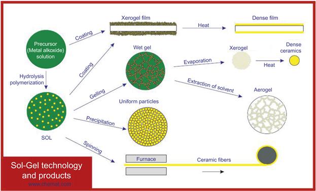
There are two generic variations of the sol–gel technique [12]. One is called the colloidal method; the other is called the polymeric (or alkoxide) route. The differences between the two stem from the types of starting materials (precursors) that are used. Both routes involve suspending or dissolving the precursor(s) in a suitable liquid, usually water for the colloidal route and alcohol for the polymeric route. The precursor is then activated by the addition of an acid (such as hydrochloric acid) or a base (such as potassium hydroxide). The activated precursors then react together to form a network by condensation. The network grows and ages with time and temperature until it is the size of the container. At this point, the viscosity of the liquid increases at an exponential rate until gelation occurs, i.e., no more flow is observed. Figure 3.2 shows the basic reaction schemes for the sol–gel process.
In the 1990s Chemat Technology (www.Chemat.com) developed a sol–gel treatment technology under a grant from United States Environmental Technology [13]. The objective of the project was to demonstrate the feasibility of formation of environmentally benign nonsurface pretreatment water-based primers for adhesive bonding. Nonchromate corrosion inhibitors were identified for the water-based primers. A family of water-based, nonsurface pretreatment solutions were formulated. The developed primers are useful for treating aluminum alloys, titanium alloys, and steels.
3.7 Surface Treatment of Plastics
An important and relevant difference between metals and plastics is their surface energy. Polymers have inherently lower surface energy than metals (assuming they are contaminant-free) and tend to form intrinsically poor adhesion bonds without some type of treatment. Adhesion is the mechanical resistance to separation of a bonded system and involves the outer surface of a material. Treatment only impacts the region near the surface and does not alter the bulk properties of the plastic parts.
In the dawn of plastic technology, chemical priming was the only method of surface preparation. Soon after, the first rudimentary machines were developed to treat polymer surfaces, increasing their polarity and surface energy, and making them acceptable for the various laminating, coating, and decorating processes. The flame and corona treatment methods gradually evolved through the 1960s and 1970s. With solvent-based systems predominant, major breakthroughs came slowly. The advent of waterborne, and then energy-cured, systems changed the pace of development. Suddenly, marginal treatment levels (34–38 dynes/cm) caused serious adhesion bond quality problems. Films that had been readily printable exhibited pinholes, fisheyes, ink liftoff, and other defect types. The remedy was to increase the treatment level to a part surface energy of 40 dynes/cm or higher.
There are chemical, physical, and bulk treatment methods available for adhesion enhancement. Chemical modification techniques include those usually requiring wet or chemical reactions as the primary means of altering the surface such as wet etching, grafting, acid-induced oxidation, and plasma polymerization. Physical surface treatment methods include corona discharge, ion or electron beam, photon beams (laser, ultraviolet light, and X-ray), plasma discharge, and flame oxidation. Bulk methods involve additives, blending, or recrystallization, all of which affect the bulk properties of plastics.
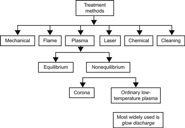
This section describes the significant techniques available for the treatment of plastic surfaces to enhance adhesion (Figure 3.3). Not all methods have wide commercial application. Some of the techniques are limited in the scope of their use. For example, chemical treatment (acid-induced oxidation) is the most frequently used method to impart adherability to plastic surfaces. Plasma treatment is limited to smaller components and parts. Flame and corona treatments are effective for continuous films (often called webs) and thin sheets of plastic, usually operated at high speeds.
3.7.1 Effect of Treatment on Plastic Surfaces
The changes that occur in the surface of plastics by applying the treatment methods are the result of the four processes of cleaning, ablation, cross-linking, and surface chemical modification (most commonly oxidation). Common treatment methods include corona, flame and plasma treatment, and chemical etching, all of which serve to increase the surface energy of plastics. The polar component of surface energy should be increased by 15–20 dynes/cm to achieve proper adhesive bonding in polymers such as polyolefin, polyphenylene sulfide, polyaramide, and others [14]. The other changes in the plastic surfaces include removal of weak materials, strengthening of the surface (by cross-linking), and increased surface roughness.
The increase in surface energy of plastic occurs through the surface oxidation of the polymer chains. For halogenated polymers, such as chlorinated and fluorinated polymers, surface modification involves significant dehalogenation, the removal of chlorine and fluorine atoms from the surface molecules. In general, surface treatments can be viewed as a transfer of energy to the surface of plastics. In almost every case, the dissipation of treatment energy on the plastic surface results in more than one change to the surface; these changes are described below.
The cleaning, or removal of contamination, including process oils, dirt, waxes, mold release agents, and exuded plasticizers, is an important result of surface treatment. Methods involving chemicals such as solvent cleaning and etching, if not properly used, can leave behind a residue that may interfere with adhesive bond formation. Clean surfaces must be protected due to rapid reacquisition of contamination from the ambient atmosphere.
Plastic surfaces often contain a low molecular polymer such as an oligomer, or loosely bonded matter, creating a weak boundary layer. There is some debate about production of low molecular weight polymers as a result of surface treatment [15]. Loosely bonded materials may originate from the plastic part itself and from additives incorporated such as pigments, processing aids, and mold release agents. They may also have been acquired externally as a result of contact with contaminated surfaces or exposure to a contaminated environment. The treatment methods remove loose material from the part surface. One mechanism for removal of material from the part’s surface material is ablation, which is the degradation and conversion of organic matter into volatile species.
The electrical discharge at the plastic surface during corona treatment reacts with the polymer molecules, generating free radicals. The presence of free radicals allows cross-linking and functionalization on the plastic surface with and without chain scission. The radicals rapidly react with ambient oxygen and produce peroxide groups that can decompose and give rise to a variety of polar groups. These groups include hydroxyl (OH), carbonyl (C![]() O), and carboxylic acid (O
O), and carboxylic acid (O![]() C
C![]() OH). The presence of these groups has been confirmed by ESCA (see Chapter 4 for a description of this technique).
OH). The presence of these groups has been confirmed by ESCA (see Chapter 4 for a description of this technique).
Corona treatment is believed to roughen the plastics by the degradation of amorphous regions of the polymer surface [16]. The belief is that corona treatment does not impact the crystalline region of the surface, preferentially attacking the relatively weak amorphous regions. Degradation and subsequent removal of the amorphous material leads to the increased roughening of the surface of plastics such as polyethylene [17–19]. A rough surface provides a much larger adhesive contact area than a smooth surface.
Plasma treatment oxidizes the surface of the polymer in the presence of oxygen. It can thus remove organic contaminants from the surface. Early studies have concluded that the cross-linking of low molecular weight surface species is the mechanism for eliminating a weak boundary layer [20]. More recent research has attributed the effectiveness of plasma treatment to surface cleaning, ablation of surface polymer chains, surface cross-linking of polymer chains, and introduction of polar functional groups that result in increased surface energy [21].
The mechanism of flame treatment is the thermal oxidation of the polymer surface. The flame temperature may exceed 2000°C. It can clean the surface and remove the weak boundary layer by vaporizing surface contamination and low molecular weight polymers.
Chemical treatment or etching oxidizes the plastic surface similarly to corona treatment. For instance, chromic acid is used to etch the surface of polyethylene and polypropylene. An increase in etching time and temperature intensifies the surface treatment by increasing the degree and depth of oxidation.
3.7.2 Surface Cleaning
Nonmetallic material, namely plastics, should be degreased, if necessary, with an aqueous detergent solution, followed by a thorough rinse with clean water, and dried. The detergent can be substituted by a solvent. Either solvent or detergent solutions can remove mold release agents or waxes from the plastic part surface. Effective solvents include methyl ethyl ketone, acetone, and methanol, depending on the plastic type. Resistance of the plastic to the solvent should be considered during solvent selection to prevent dissolving or degrading the plastic during cleaning. The chemical surface cleaning step is unnecessary if a treatment technique, such as plasma treatment, adequately cleans the surface along with surface modification.
3.7.3 Mechanical Treatment (Surface Roughening)
Surface roughening and sanding of plastics accomplishes the same purposes as with metals. Essentially, loose and unstable polymers are removed from the surface, thus increasing contact surface area. This step is not pertinent if there are decorative and esthetic considerations that require an even, smooth surface. For instance, if a plastic part is painted or laminated to a thin film, the application of surface roughening and sanding may be impossible or limited. When applicable, plastic surfaces are usually hand-sanded or sand-blasted to impart roughness (increased contact surface area) to the part surface.
3.7.4 Corona Treatment
Corona discharge usually takes place at atmospheric pressure in contrast to low temperature (or cold) plasma, which requires a vacuum. Corona is a stream of charged particles such as electrons and ions that are accelerated by an electric field. A corona is generated when a space gap filled with air or other gases is subjected to a sufficiently high voltage to set up a chain reaction of high-velocity particle collisions with neutral molecules, resulting in the generation of more ions. One important such species is atomic oxygen (O) generated by the UV light in the corona stream:
The atomic oxygen (O) reacts with hydrogen and carbon on the film surface generating ![]() OH and C
OH and C![]() O groups which form hydrogen bonds with adhesives.
O groups which form hydrogen bonds with adhesives.
Corona discharge is applied to treat the surface of plastics, rendering them adherable (Figure 3.4). In this method, the plastic article is exposed to a corona discharge produced by high-frequency, high-voltage alternating current. The corona dosage is calculated from the following equation:
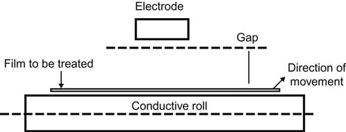
There are three types of treating configurations, all consisting of the same parts including an electrode, an electrical insulator (or dielectric), and a return path (or ground). The differences among the three configurations are in the location of the electrode. In a conventional system, the web passes over a roll that is covered with insulating material such as a silicone rubber. A metal electrode is suspended above the roll so that an air gap of 1.5–2.5 mm exists between the electrode and the insulated roll. High voltage operates across the air gap, ionizing it, and forming a corona discharge curtain between the electrode and the material (e.g., film) that is being treated. The conventional configuration can be used only with nonconductive material. The second configuration is called bare roll (in which the electrode is covered with a dielectric (usually ceramic) and the roll is made of anodized aluminum. In the third configuration, called double dielectric, the roll and the electrodes are covered with dielectric material.
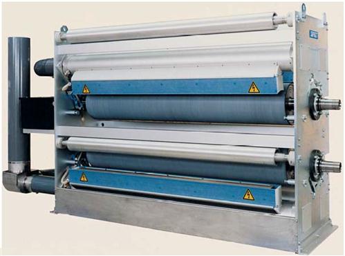
The main parameters for the control of the treatment process include the voltage, width of the air gap between electrodes, film/web speed, and the width of the electrodes. Most machines allow treatment of one side of the web (Figure 3.5) and require two passes for two-sided treatment. There are also machines that are equipped with two sets of electrodes for one pass, two-sided treatment.
Effectiveness of corona treatment depends on the type of polymer. The duration of corona discharge treatment in air has a strong influence on the surface energy of the plastic. Surface energy increases more slowly as the crystallinity of the polymer being treated increases (from lower to higher, PE<PEP<PP). Longer exposure time is required to achieve the same level of surface energy.
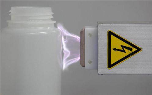
3.7.4.1 Three-Dimensional Corona Treatment
Three-dimensional (3D) corona treatment, as the name indicates, is aimed at surface modification of objects with a third dimension, compared to a web (2D). Plastic objects are treated by 3D corona discharge to promote adhesion for printing, painting, coating bonding, and labeling [22–24].
A 3D corona discharge head has a dielectric enclosure with two small electrodes made of medium thickness, bare aluminum or stainless steel wire, and connected to a high-voltage power supply and fan [25]. When a high voltage exceeds the air breakdown value (30 kV/cm), an electrical arc forms. This high-current arc is blown out from the enclosure by the airstream and is usually several centimeters long and one millimeter in diameter.
When the arc strikes a solid object (Figure 3.6), it travels across the surface and returns back into the enclosure [25]. The treatment is achieved by moving the object under the discharge head or by moving the head over the object. The arc is essentially a 1D object (like a wire), and a treatment of 3D surfaces requires at least two heads. It is difficult to treat objects with complicated geometry, especially with internal cavities or channel structures, including tubing. The average power required for one head operation is about 500 W. The effective power dissipated in the arc could be as low as 50 W. Most of the ions and electrons travel between the two electrodes along the arc trajectory where the main transfer of energy occurs.
The plasma effect on the material strongly depends on the exposure time because each material requires a minimum exposure time to activate its surface. The required level of surface modification depends on the application (e.g., printing, bonding, and coating) as well as on the applied ink, adhesives, coatings, and curing process.
Occasionally, there is not a sufficient window for the necessary exposure time and thermally safe material handling for 3D corona treaters. This is especially true of tough-to-treat materials (plasmaphobic) in which the surface gets burned rather than modified. This is also the case for heat-sensitive materials, thin wall plastic objects, wires with thin insulation, fiber optics, thin coating layers, etc. This problem is partly solved by installation of several discharge heads along the process line. If the problem is not solved, other techniques are used to avoid burning.
3D corona treaters also generate ozone. To reduce high ozone concentration, special filters are required to comply with clean room environment regulations for the medical and semiconductor industries. A high-voltage signal applied to the electrodes usually has an audible frequency (60 Hz and upwards). Electrical breakdown takes place during each half-period of the cycle and produces a small shock wave with a distinctive sound. This may generate significant amounts of noise in multiple head discharge systems, requiring noise abatement and hearing protection.
3.7.4.2 Corona Treatment Under Chemical Atmosphere
One of the most important commercial polyolefin films is biaxially oriented polypropylene (BOPP) film. Because of its use in a variety of applications such as food packaging, multipurpose packaging, and adhesive-tape packing [2–4], BOPP films have low hydrophilicity and do not allow printing ink or adhesives well. Its surface is thus modified to improve wettability and adhesion. The most common method for surface modification of BOPP and other polyolefin films is corona treatment which offers the benefits of continuous and inline operation and cost effectiveness.
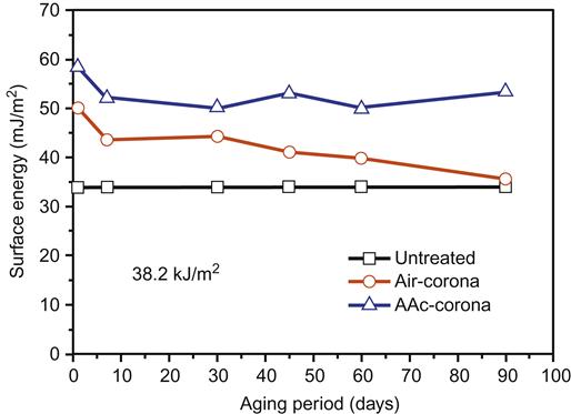
Corona treatment introduces [26] polar functional groups such as hydroxyl, carbonyl, and carboxylic groups onto the film surfaces. The presence of these functional groups on the film surface raises the film surface-free energy. Thermodynamic driving forces and the small sizes of these groups, however, result in the overturning or “inversion” of the polar group which migrates below the film surface [27,28]. This phenomenon is called hydrophobic recovery. In just 30 days after treatment, surface-free energy of a film like polypropylene can lose the effect of modification significantly, thus rendering it practically useless for most applications [29].
The mobility of polymer chains at the surface of the film is the reason polar groups invert inward. To eliminate the time dependence of corona treatment, the mobility of polymer chains at the surface may be constrained by grafting bulky functional groups [30]. The key issue is, however, that postcorona treatment surface grafting involves additional steps, which significantly lengthen the process and increase the cost of the film. Technology has been developed to introduce organic grafting compounds into the atmosphere of the corona process, which is usually air.
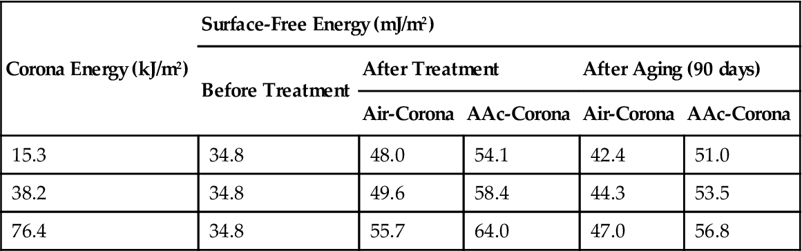
Introduction of vapor of acrylic acid (AAc) monomer into the corona region has proved successful. Surface wettability of BOPP films were improved (surface energy increased) by comparison with the standard air corona treatment (Table 3.4). The hydrophilicity lasted for more than 90 days of aging (Figure 3.7).
Table 3.4
Surface-Free Energy of Aged BOPP Films at Ambient Temperature [26]
| Corona Energy (kJ/m2) | Surface-Free Energy (mJ/m2) | ||||
| Before Treatment | After Treatment | After Aging (90 days) | |||
| Air-Corona | AAc-Corona | Air-Corona | AAc-Corona | ||
| 15.3 | 34.8 | 48.0 | 54.1 | 42.4 | 51.0 |
| 38.2 | 34.8 | 49.6 | 58.4 | 44.3 | 53.5 |
| 76.4 | 34.8 | 55.7 | 64.0 | 47.0 | 56.8 |
3.7.5 Flame Treatment
Flame treatment is a commercial process to render polyolefins and polyethylene terephthalate adherable. The polymer article (e.g., film) is passed over an oxidizing flame formed by an oxygen-rich (relative to stoichiometry) mixture of hydrocarbon gas. Variables affecting the extent of oxidation include the flame characteristics (e.g., excess oxygen) as well as the speed of the article movement. Gas flame contains excited fragments and species such as atomic oxygen (O), NO, OH, and others that can abstract hydrogen from the surface of the polymer that is replaced by oxygenated functional groups (mostly ![]() C
C![]() O and
O and ![]() OH). Figure 3.8 depicts the flow diagram of flame treatment system.
OH). Figure 3.8 depicts the flow diagram of flame treatment system.
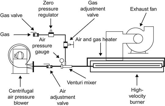
Polyethylene and polypropylene have a surface tension of 30 dynes/cm that must be raised to a minimum of 38 dynes/cm (preferably to 42 dynes/cm) to render their surfaces adherable. Flame treatment is the most widely used method of pretreatment. It is flexible and reliable if carefully controlled. It enables the treatment of uneven and curved surfaces. It uses a mixture of air at 138–345 kPa and a fuel gas at a (low) pressure of 1.7 kPa. The gas can be butane, propane, natural gas (methane), and coal gas.
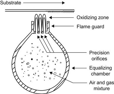
For the flame to be effective, it must be oxidizing (represented by a blue flame). Correct flame control is very important. A basic flamer will complete simple work; specially designed flame control systems are recommended for routine operations and long production runs. These systems are fitted with gas and air control valves to compensate for pressure fluctuations, ensuring that the mixture is always at its optimum. Safety devices, such as flame failure shutdown, are fitted as standard. Automatic ignition is also standard. Flame nozzle design is important for these normally single or double row ribbon burners because they give a more stable flame shape and characteristic. “Flame throwers” are inefficient and unreliable. Flame control and position of the item in the flame are critical. Setting up the flamer is also very important (Figure 3.9). Over-flaming will damage the surface of the product, while under-flaming can cause failure with the ink adhesion [34].
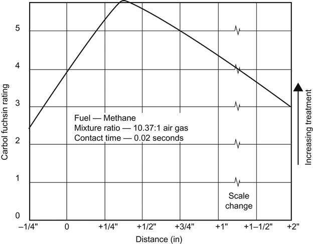
It is imperative to find the correct flame treatment suitable to the component in question. Key factors include the gas type, gas to air ratio, burner type, gas flow rate, flame distance, and flame passage speed (treatment time). Excessive treatment of the surface results in degradation of the polypropylene and, therefore, poor adhesion. Insufficient treatment, however, fails to modify the surface adequately, leading to poor adhesion. It is often a rather delicate procedure to find the proper conditions and great care must be taken in the experimentation (Figure 3.10).
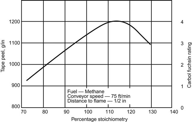
During flame treatment, all hydrocarbon gases combine with oxygen to produce heat, as shown here for methane:
The above equation indicates complete combustion of the fuel gas methane. The volume of air required for complete theoretical combustion of gas (such as methane) is called the stoichiometric volume (100%). A flame containing an excess (>100% stoichiometry) of air is referred to as an oxidizing flame; a flame that does not have sufficient air (<100% stoichiometry) to complete combustion is a reducing flame. Figure 3.11 [34] shows the effect of using more or less air than the stoichiometric volume on the tape peel strength of polyethylene or polypropylene. A maximum value develops at about 115% stoichiometry or 15% excess air.
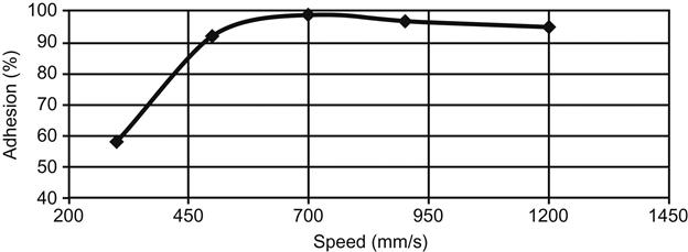
In Figure 3.12 [26], the influence of the flame passage speed over the plastic on the adhesion (shown as percentage of maximum adhesive bond strength) between the adhesive and glass matte-reinforced thermoplastic (GMT) is presented. The machine supplier often provides assistance with the optimization of the system.
The speed of the conveyer greatly effects the flaming. As a rule, the higher the speed of passage of the item through the flame, the less likelihood there is of damage to the surface. High gloss surfaces are susceptible to blooming, which reduces the gloss. Higher speeds help reduce blooming. Conveyers are constructed from metal mesh, which must be of sufficient length to allow the mesh to cool. Hot meshes will mark plastic components.
Flame treatment is not effective in the adhesion treatment of perfluoroplastics. The data in Table 3.5 reveal a large increase in the bond strength of polyvinyl fluoride (PVF) and ethylene chlorotrifluoroethylene (ECTFE) after flame treatment. The fluorine-to-carbon (F/V) ratio of PVF remained unchanged but the O/C ratio increased significantly. In the case of PTFE, the F/C ratio actually increased, which could explain the drop in the bond strength as a result of flame treatment. The flame most likely removed contamination that had previously masked some of the F atoms on the surface.
Table 3.5
Effect of Flame Treatment on the Surface Composition and Adhesion Bond Strength of Fluoropolymers
| Polymer/Treatment | Surface Chemical Analysis (%) by ESCAa | Bond Strength, Nb | ||||||
| F/C Ratio | Cl/C Ratio | O/C Ratio | Cl | C | F | O | ||
| PVF | ||||||||
| No | 0.41 | – | 0.011 | – | 70.4 | 28.8 | 0.8 | 360 |
| Yes | 0.41 | – | 0.065 | – | 67.6 | 28.0 | 4.4 | 3240 |
| ECTFE | ||||||||
| No | 0.61 | 0.27 | – | 14.3 | 53.2 | 32.5 | – | 240 |
| Yes | 0.25 | 0.12 | 0.087 | 8.0 | 68.8 | 17.2 | 6.0 | 2980 |
| PTFE | ||||||||
| No | 1.60 | – | – | – | 38.4 | 61.6 | – | 420 |
| Yes | 1.94 | – | – | – | 34.0 | 66.0 | – | 80 |
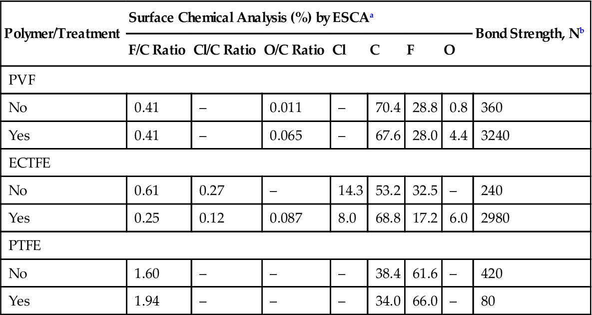
aElectron spectroscopy for chemical analysis.
bBond strength in newtons (N) using lap shear test and an epoxide adhesive.
3.8 Methods for Evaluating Effectiveness of Surface Preparation
Before actual bonding, the subjective “water-break” test, or the quantitative and objective contact-angle test, may be carried out. After bonding, the effectiveness of surface preparation may be determined by measuring the bond strength and determining the mode of the failure of the adhesive joint.
3.8.1 Dyne Liquids
This method is common for estimating the treatment level of plastic surfaces in manufacturing/production environments. It involves using solutions made from a mixture of two chemicals that produce liquids (dyne) with surface tension in the range of 30–70 dynes/cm. The test consists of placing droplets of the various dyne liquids on the treated surface and observing the spreading of the drops in 2 s. Successive liquids with different surface tensions allow narrowing of the surface tension range of the plastic surface. This method is subjective, but it provides a rapid means of assessment of the treatment level, particularly useful in a production environment. There are also pens that operate similarly to dyne liquids. A more quantitative approach is the measurement of contact angle, which decreases with an increase in treatment level. A perfect wetting liquid forms a contact angle of zero on the solid surface.
3.8.2 Water-Break Test
This test depends on the observation that a clean surface (one that is chemically active, or polar) will hold a continuous film of water, rather than a series of isolated droplets. This is known as a water-break-free condition. A break in the water film indicates a soiled or contaminated area. Distilled water should be used in the test, and a drainage time of about 30 s should be allowed. Any trace of residual cleaning solution should be removed to avoid a false conclusion. If a water-break-free condition is not observed on the treated surface, it should not be used for bonding. The surface should be recleaned until the test is passed. If failures continue to occur, the treating process itself should be analyzed to determine the cause of the problem [3].
3.8.3 Contact-Angle Test
Wettability may also be determined by measuring the contact angle between the polymer surface and the drop of a reference liquid such as distilled water. A small contact angle indicates that the liquid is wetting the polymer effectively, while large contact angles show that the wetting is poor. Every surface has a critical surface tension, γc, of wetting. Liquids with surface-free energies below γc will have zero contact angles and will wet the surface completely. In contrast, liquids with surface-free energies above γc will have finite contact angles. The critical surface tension is in units of dynes/cm at 20°C. Contact angles for untreated materials vary from 37° to 48° for relatively polar materials such as nylon to respective highs of 100° and 97° for the nonpolar, unbondable silicone and polyethylene resins. After exposure to activated argon plasma, contact angles are reduced to 40° for polymethyl methacrylate (PMMA) and to 19° or less for nylon, polystyrene, polyethylene, and room temperature vulcanization (RTV) silicone [7]. Zissman and others [36,37] have written comprehensively on surface tension phenomena relating to adhesion.
Table 3.6 gives the treatment values recommended for a number of plastics as a function of the adhesive coating system and the manufacturing processes. Note that, as discussed earlier in this section, waterborne adhesives universally require higher surface energy levels than solvent-based systems.
Table 3.6
Suggested Surface Energy (Treatment Level) for Various Plastics Adhesion Substrates
| Process | Printing Processes | Other Processes | |||||||||||||||||
| Flexo and Gravure | Litho | Offset, Letterpress | Screen and Pad | Laminating(6) | Coating | ||||||||||||||
| CoatingType | Water | Solvent | UV | Water | Solvent | UV | Water | Solvent | UV | Water | Solvent | UV | Water | Solvent | UV | Water | Solvent | UV | |
| Substrate | SPE(2) | 38 | 36 | 38 | 40 | 37 | 40 | 40 | 37 | 42 | 42 | 38 | 44 | 42 | 38 | 42 | 42 | 38 | 44 |
| 44 | 40 | 50 | 46 | 42 | 50 | 46 | 42 | 54 | 48 | 44 | 60 | 50 | 44 | 54 | 48 | 45 | 54 | ||
| PP(3) | 38 | 36 | 40 | 40 | 38 | 40 | 40 | 37 | 40 | 42 | 38 | 44 | 42 | 38 | 42 | 42 | 38 | 44 | |
| 44 | 40 | 50 | 46 | 42 | 50 | 46 | 42 | 54 | 48 | 44 | 60 | 50 | 44 | 54 | 48 | 45 | 54 | ||
| PVC(4) | 38 | 36 | 36 | 40 | 37 | 36 | 40 | 38 | 40 | 42 | 38 | 42 | 42 | 38 | 42 | 40 | 38 | 42 | |
| 44 | 40 | 50 | 45 | 42 | 52 | 45 | 42 | 52 | 48 | 44 | 60 | 50 | 44 | 54 | 48 | 45 | 54 | ||
| PET(5) | 44 | 40 | 42 | 46 | 42 | 44 | 46 | 42 | 46 | 48 | 42 | 44 | 46 | 42 | 44 | 42 | 42 | 46 | |
| 52 | 46 | 54 | 56 | 46 | 56 | 56 | 46 | 60 | 60 | 48 | 62 | 60 | 48 | 62 | 52 | 48 | 60 | ||
| PS | 38 | 35 | 42 | 40 | 37 | 42 | 40 | 38 | 42 | 42 | 38 | 42 | 42 | 37 | 42 | 42 | 38 | 44 | |
| 44 | 40 | 48 | 45 | 42 | 50 | 46 | 44 | 58 | 48 | 44 | 56 | 52 | 44 | 54 | 50 | 46 | 54 | ||
| PVDC | 40 | 38 | 42 | 42 | 40 | 42 | 42 | 38 | 42 | 42 | 40 | 42 | 42 | 38 | 44 | 42 | 40 | 44 | |
| 46 | 42 | 52 | 46 | 42 | 52 | 48 | 44 | 54 | 50 | 45 | 58 | 50 | 44 | 52 | 48 | 46 | 54 | ||
| PU | 40 | 38 | 38 | 40 | 38 | 38 | 40 | 38 | 42 | 42 | 38 | 42 | 42 | 38 | 42 | 42 | 38 | 44 | |
| 46 | 42 | 50 | 46 | 42 | 52 | 45 | 44 | 56 | 50 | 44 | 58 | 50 | 44 | 56 | 48 | 46 | 54 | ||
| ABS | 42 | 40 | 40 | 42 | 40 | 42 | 42 | 38 | 45 | 42 | 40 | 46 | 42 | 40 | 42 | 42 | 38 | 44 | |
| 46 | 44 | 52 | 46 | 45 | 52 | 48 | 46 | 52 | 48 | 45 | 56 | 52 | 45 | 56 | 48 | 46 | 54 | ||
| PTFE | 40 | 34 | 36 | 40 | 35 | 38 | 40 | 38 | 42 | 42 | 38 | 42 | 42 | 38 | 42 | 42 | 40 | 42 | |
| 44 | 39 | 52 | 45 | 40 | 52 | 48 | 44 | 60 | 52 | 46 | 60 | 56 | 46 | 56 | 50 | 48 | 54 | ||
| Silicone | 40 | 35 | 40 | 40 | 38 | 38 | 40 | 38 | 40 | 42 | 38 | 42 | 42 | 38 | 42 | 42 | 40 | 42 | |
| 44 | 40 | 50 | 45 | 42 | 52 | 48 | 44 | 56 | 50 | 46 | 60 | 56 | 46 | 56 | 50 | 48 | 54 | ||
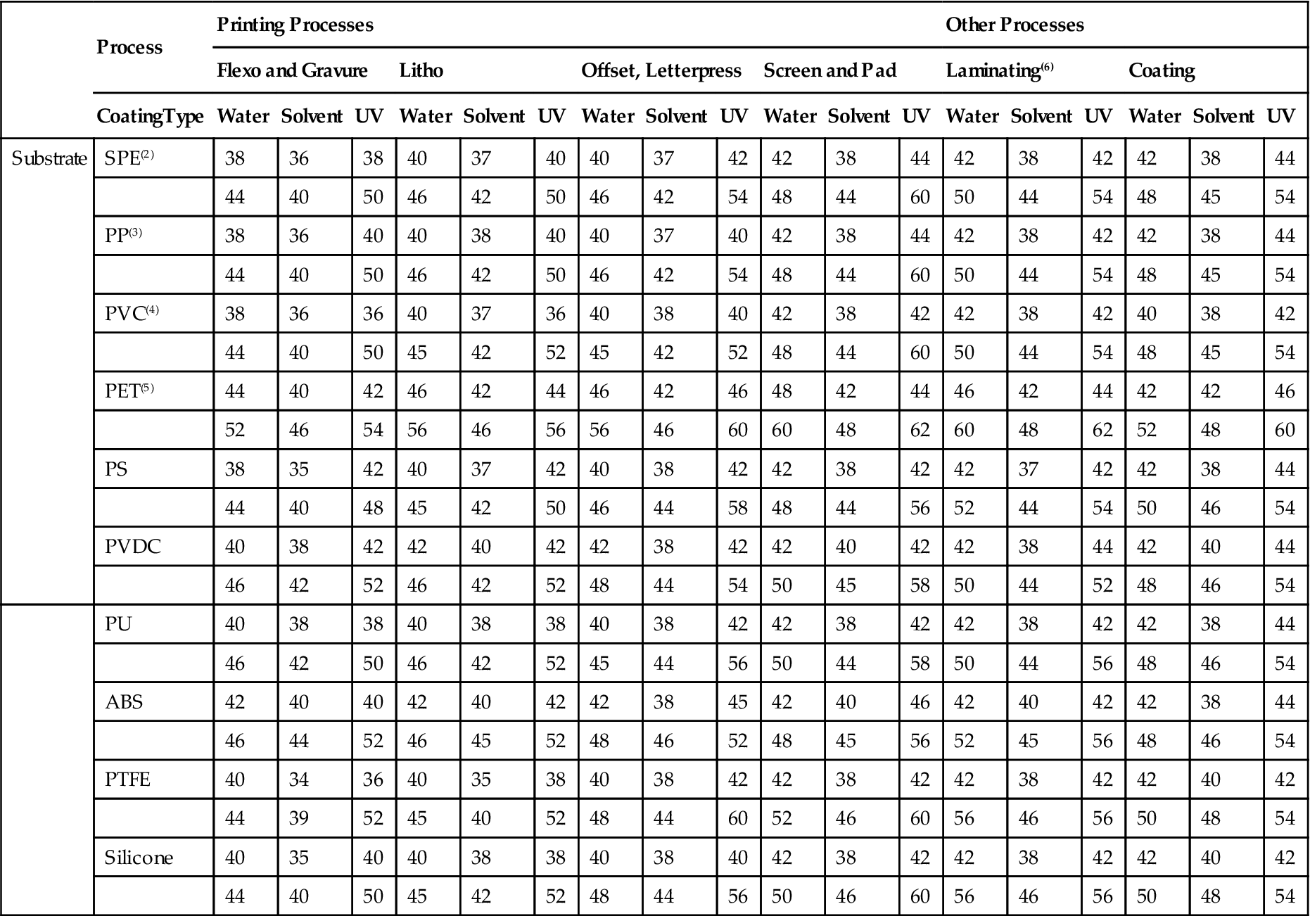
Polymer name abbreviations: PE=polyethylene, PP=polypropylene, PVC=polyvinyl chloride, PET=polyethylene terephthalate, PS=polystyrene, PVDC=polyvinylidene chloride, PU=polyurethane, ABS=acrylo butyl styrene, and PTFE=polytetrafluoroethylene.
In most cases, if the substrate is somewhere between the low and high dyne levels cited, a satisfactory bond can be obtained. For demanding production conditions (e.g., high web speeds and/or critical quality process work), it is safest to aim for the top of the range. Use Table 3.6 as a general guideline only; each operation has slightly different requirements. These data are for flame or corona treatment in an oxygen-containing atmosphere. (1) Some values theoretical. (2) Any density, any type, including films, coated board, and molded products. (3) All types, cast or molded. (4) More plasticizer generally requires levels at the high end of these ranges. (5) Unquoted. (6) For heat sealing, the surface energies of the mating PE surfaces should match closely; if both faces are treated, heat sealing can usually be accomplished over a broader and lower temperature range.
3.9 Surface Exposure Time
Surface exposure time (SET) is the time elapsed between the surface preparation and the actual bonding. After parts have been subjected to surface preparation, they must be protected from contamination during transportation and storage. The clean surface should never be touched with bare hands or soiled gloves. If more than a few hours are required between cleaning and priming, the parts should be covered, or, for still longer periods, wrapped in clean kraft paper until the priming can be carried out. After priming, the dried primer surfaces, if not to be bonded immediately, should again be protected by wrapping in kraft paper. Whether or not a primer is used prior to adhesion, these steps should be carried out. The period of time for which the parts can be safely stored in this way will vary depending on the nature of the adherends, the adhesive, the surface preparation method, and the ultimate bond strength required [38,39].
Peel tests, particularly the roller peel test, have been found to be more sensitive to variation in surface preparation than shear tests. Peel tests show that, in general, increasing SET tends to reduce the critical joint strength. If the faying surfaces are protected and the relative humidity is kept at about 50%, up to 30 days may elapse between surface preparation and actual bonding without serious loss in joining strength. Temperatures and relative humidity above normal will cause deterioration, in shorter periods of time [39,40].