
7. Natural and Character Animation
Lesson Overview
In this lesson, you’ll learn how to do the following:
• Use the Bone tool to build armatures (skeletons) of movie clips
• Use the Bone tool to build armatures of shapes
• Animate natural motion of armatures using inverse kinematics
• Constrain and pin the armature joints
• Edit the position of armature bones and joints
• Refine shape deformations with the Bind tool
• Simulate physics with the Spring feature
• Adjust the speed setting to add a sense of weight to armatures
This lesson will take approximately two and a half hours to complete. Download the project files for this lesson from the Registered Products tab on your Account page at www.peachpit.com (click the Access Bonus Content link) and store them on your computer in a convenient location, as described in the Getting Started section of this book. Your Account page is also where you’ll find any updates to the lessons or to the lesson files.

You can easily create complex and natural motion with articulations—joints between linked objects and within shapes—using the Bone tool for animation called inverse kinematics.
Getting Started
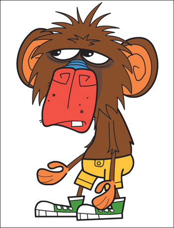
You’ll start the lesson by viewing the animated walking monkey that you’ll create as you learn about natural motion in Adobe Animate CC.
1. Double-click the 07End.html file in the Lesson07/07End folder to play the animation.

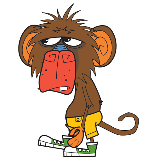
The animation depicts a cartoon monkey walking in an endless cycle with a scrolling motion in the background. His arms and legs swing naturally, and his tail curls and unfurls naturally and smoothly. In this lesson, you’ll build the armature (a skeleton) that controls the monkey and all his limbs, and then animate his walk cycle.
2. Double-click the 07Start.fla file in the Lesson07/07Start folder to open the initial project file in Animate.
3. Choose File > Save As. Name the file 07_workingcopy.fla, and save it in the 07Start folder. Saving a working copy ensures that the original start file will be available if you want to start over.
Natural Motion and Character Animation with Inverse Kinematics
When you want to animate natural motion of an articulated object (one that has multiple joints), such as a walking person, or as in this example, a walking monkey, Animate CC makes it easy to do so with inverse kinematics. Inverse kinematics is a mathematical way of calculating the different angles of a jointed object to achieve a certain configuration. You can pose your object in a beginning keyframe, and then set a different pose at a later keyframe. Animate will use inverse kinematics to figure out the different angles for all the joints to smoothly get from the first pose to the next.
Inverse kinematics makes animating easy because you don’t have to worry about animating each segment of an object or limb of a character. You just focus on the overall poses, and Animate will take care of the rest.
Building your first armature to animate a character
When animating a clearly articulated object (a character with limbs and joints), first determine which pieces of the character need to move. At the same time, examine how those pieces connect together and move. This will almost always be a hierarchical structure, like a tree, starting from a root and branching out in various ways. This structure is called the armature, and, like a real skeleton, each rigid piece that makes up the armature is called a bone. The armature defines where your object can bend and how the different bones are connected.
You use the Bone tool (![]() ) to create your armature. The Bone tool tells Animate how a series of movie clip instances are connected, or provides the jointed structure within a shape. A connection between two or more bones is called a joint.
) to create your armature. The Bone tool tells Animate how a series of movie clip instances are connected, or provides the jointed structure within a shape. A connection between two or more bones is called a joint.
1. In your 07working_copy.fla file, open the Library panel and view the graphics for the monkey character that have already been created and imported for you.

2. Drag all the pieces of the monkey from the Library panel onto the Stage, and drag two instances each of the foot, hand, leg, lower leg, arm 1, and arm 2. Arrange them so you have the different segments in roughly the arrangement you need to form the whole body (with head, body, pelvis, two arms, and two legs). For the back arm, use the Free Transform tool to rotate all three of the pieces (arm 1, arm 2, and hand) 180 degrees.

Keeping some space between the pieces will make connecting the bones for your armature easier. Don’t worry about getting the pieces looking exactly right because you’ll move them together in a later step.
3. Select the Bone tool.
4. Click the middle of the monkey’s chest and drag with the Bone tool to the top of his left upper arm. Release the mouse button.

Your first bone is defined. Animate shows the bone as a straight line with a square at its base joint and a circle at its tip joint. Each bone is defined from one joint to the next.
The following shows the bones and their relationship to each other without the full rendering of the movie clips (with Show All Layers As Outlines enabled).
5. Now click the end of your first bone (at the monkey’s shoulder) and drag it to the top of his lower arm (his elbow). Release the mouse button.

Your second bone is defined.
6. Click the end of your second bone and drag it to the base of the monkey’s hand. Release the mouse button.
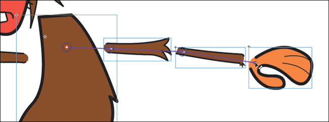
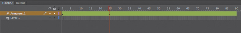
Your third bone is defined. Note that the four movie clip instances, which are now connected with bones, have been moved to a new layer with a new icon and the default name Armature_#. This special type of layer keeps your armatures separate from other objects on the Timeline such as graphics or motion tweens.
![]() Note
Note
The first Armature layer created in a pristine file will be called “Armature_1” and each time you add a new Armature layers its name will be incremented by one. Don’t worry if the name of your Armature layer doesn’t match the one in these screenshots.

7. Select the Selection tool and experiment with grabbing the last bone in the chain (the monkey’s hand) and moving it up and down the Stage.
Because the bones connect the whole arm, moving the hand causes the forearm and the upper arm to move as well.
Extending your armature
You’ll continue to build out the armature of the monkey by connecting his other arm, head and pelvis, and legs.
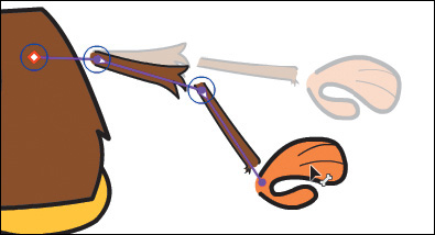
1. Click the base of your very first bone (in the monkey’s chest) and drag the Bone tool to the top of his other upper arm. The first bone is considered your “root bone.” Release the mouse button.
2. Continue creating more bones to the base of the other hand.
Your armature now extends out in two directions: one for the monkey’s left arm and one for his right.

3. Click the base of your very first bone (in the monkey’s chest) and drag the Bone tool to middle of the pelvis.
4. Extend the armature from the pelvis down to both of the monkey’s lower legs. The pelvis will branch off to the right and left thighs, lower legs, and feet.
5. Lastly, connect the torso to the monkey’s head.
Your armature now connects all the pieces of the monkey, defining how each piece can rotate and move in relation to the other pieces in the armature.

Armature hierarchy

Moving the bones of the armature
Now that you’ve connected each of the movie clips with your bones in a complete armature, you can edit each bone’s relative position. You initially placed them with gaps between the bones to make connecting them easier. Holding down the Alt/Option key allows you to move the position of any bone in your armature.
1. Select the Selection tool.
2. Hold down the Alt/Option key and move the monkey’s left upper arm closer to his body. You can also use the Free Transform tool.
The upper arm is repositioned, but the armature remains intact.
3. Hold down the Alt/Option key and move all the parts of the monkey’s body closer together to eliminate the gaps in his joints.
The monkey and its armature should look similar to the following figure.

Modifying the position of the joint
If you want to change the point where one bone connects to another—the joint—use the Free Transform tool to move its transformation point. This also moves the rotation point of the bone.
1. If, for example, you made a mistake and attached the end point of your bone to the middle of the monkey’s hand rather than at the base, his hand would rotate unnaturally.

2. To modify the position of the joint, select the Free Transform tool and click the hand to select it. Move the transformation point to the base of the hand.

3. The bone now connects to the new transformation point of the movie clip, and as a result, the hand rotates around the wrist.

Rearranging the stacking order
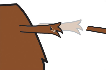
When you build an armature, the most recent bone will move to the top of stack in your graphics. Depending on the order in which you connected your bones, the individual movie clips may not overlap correctly. For example, in the previous task, the monkey’s feet and legs may not overlap in a way that makes sense. One leg should be behind his pelvis, and one leg should be in front. Use the Modify > Arrange command to change the stacking order of the movie clips in your armature so they overlap each other correctly.
1. Select the Selection tool and Shift-select the three movie clips that make up the monkey’s back leg.
2. Choose Modify > Arrange > Send To Back, or right-click and select Arrange > Send To Back (Shift+Ctrl+Down/Shift+Command+Down).

The selected bones of the armature move to the bottom of the stacking order, so his right leg is now behind all the other pieces of his body.

3. Select the three clips that comprise the monkey’s right arm and use the Modify > Arrange command to move his right arm behind the body.
4. Select the three pieces of the monkey’s left arm and choose Modify > Arrange > Bring To Front, or right-click and choose Arrange > Bring To Front (Shift+Ctrl+Up/Shift+Command+Up).
The selected bones of the armature move to the top of the stacking order, so his left arm is now above all the other pieces of his body.
5. You may need to move individual bones forward or backward so they overlap correctly. For example, in the monkey’s leg, his pants and his shoes should overlap his lower leg.
6. Select the Selection tool and move the armature around to see how the right and left arms and legs of the monkey move behind or in front of his body, and make any corrections, if needed.
![]() Note
Note
Use Modify > Arrange > Send To Back to move selected graphics all the way to the bottom of the stacking order, or use Modify > Arrange > Send Backward to move the selected graphics just one level back. Similarly, use Bring To Front to move graphics to the top of the stacking order or use Bring Forward to move graphics just one level up.
Creating a Walk Cycle
A walk cycle is a basic looping animation showing a character walking. Not only are the swinging arms and legs coordinated, but for the most convincing walk cycles, the body and head are also animated for the subtle bobbing motion that provides the sense of weight. Walk cycles can be enormously complicated (deceptively so), but can imbue a character with a lot of personality.
Armatures help make creating a walk cycle easier because you can move the character’s limbs in place to define the key poses in the cycle. Think of poses as keyframes for the animation. In the next task, you’ll create a simple walk cycle defined with four poses.
Posing your armature
You have an initial pose for your monkey in frame 1. You will insert three additional poses for the monkey to create a basic walk cycle. The fifth pose will be a duplicate of the very first pose, so when the animation loops, the cycle will be seamless. The four basic poses can be summarized in the following diagram:

Graphic by Ajaykarat at English Wikipedia CC BY 3.0
In the first pose, the foreground leg is forward and the background leg is back. In the second pose, the legs pass each other. In the third pose, the background leg is forward and the foreground leg is back. In the fourth pose, the legs pass each other again. The arms swing in the opposite direction from the legs.
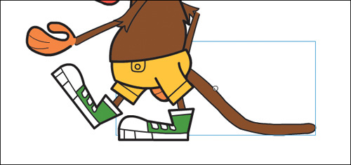
1. Using the Selection tool, drag the monkey’s left foot and move it behind him. Try to keep his foot flat on the ground, which will help him look like he’s pushing the ground rather than bicycling in the air.
As you drag his foot, the bones that are connected to it also move. You may also have to drag his thigh or his lower leg to get the position of the armature just right. If you have trouble controlling the armature, don’t worry! It takes practice, and in the following sections, you’ll learn more tips and tricks to constrain or isolate certain joints to make precision positioning.
2. Move the monkey’s right foot so it is stepping forward.
3. Move the monkey’s left arm forward and his right arm behind him.
Your first pose is completed in frame 1 of your armature layer.

Isolating the rotation of individual bones
As you pull and push on the armature to create your pose, you may find it difficult to control the rotation of individual bones because of their linkages. Holding down the Shift key as you move individual bones will isolate their rotation.
1. Select the monkey’s left hand.
2. With the Selection tool, drag the hand.
The whole arm moves to follow the motion of the hand.
3. Now, holding down the Shift key, drag the monkey’s hand.

The hand rotates around the wrist, but the rest of the arm doesn’t move. The Shift key isolates the rotation of the selected bone.
Holding down the Shift key helps you isolate the rotations of individual bones so that you can position your poses exactly as you want them. Return to the monkey’s legs and arms to make any necessary adjustments using the Shift key.
Pinning individual bones
Another way you can more precisely control the rotation or position of your armature is to fix individual bones in place, leaving the child bones free to move in a different pose. You do this by using the Pin option in the Properties panel.
1. Select the Selection tool.
2. Select the bone in the monkey’s right thigh.
The bone becomes highlighted, indicating that it is selected.

3. In the Properties panel, select the Pin option.
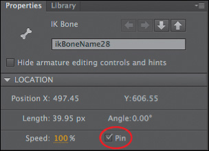
The tail, or end that connects to the child bone, is fixed to the Stage in the current position. A white circle with a black dot appears on the joint to indicate that it is pinned.

4. Drag the last bone (the foot) in the monkey’s leg.

Only the last two bones move. Note how the armature motion is different when using the Pin option versus using the Shift key. The Shift key isolates an individual bone and all the rest of the bones connected to it. When you pin a bone, the pinned bone remains fixed, but you’re free to move all the child bones.
![]() Tip
Tip
You can also select a bone and click its tail when your cursor changes to the icon of a pushpin. That selected bone will be pinned. Click again to unpin the bone.

Disabling and Constraining Joints
Before you insert the rest of the poses, you can add refinements to your armature that will make it easier to position the monkey’s limbs. The various joints of the monkey can freely rotate, which isn’t particularly realistic, particularly in his pelvis. Many armatures in real life are constrained to certain angles of rotation. For example, your forearm can rotate up toward your bicep, but it can’t rotate in the other direction beyond your bicep. Your hips can wiggle around your torso, but not by very much. These are constraints that you can also impose on your own armature. When working with armatures in Animate CC, you can choose to constrain the rotation for various joints or even constrain the translation (movement) of the various joints.
Disabling the rotation of joints
If you drag the monkey’s pelvis, you’ll see that the bone that connects the torso with the pelvis can rotate freely, which allows wildly unrealistic positions.

1. Select the bone that connects the monkey’s torso with his pelvis.
The bone is highlighted.

2. In the Properties panel, deselect the Enable option in the Joint: Rotation section.

The circle around the joint at the head of the selected bone disappears, which means that the joint no longer is able to rotate.

3. Now drag the pelvis.
The pelvis no longer can rotate around the joint in the torso.

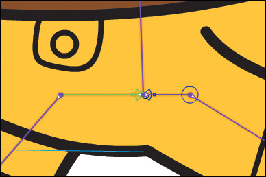
Constraining the range of rotation
There’s still some work to do with the monkey’s pelvis. Although it can’t freely rotate around the joint in the monkey’s torso, it can still rotate around the child joint 360 degrees. You can constrain that range of rotation.
1. Click one of the bones that connects the monkey’s pelvis with one of his legs to select it.
The bone becomes highlighted.

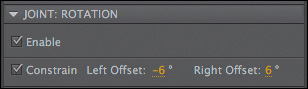
2. In the Properties panel, select the Constrain option in the Joint: Rotation section.

The angle indicator changes from a full circle to a partial circle on the joint, showing the minimum and maximum allowable angles and the current position of the bone.
3. In the Properties panel, set the Left Offset rotation angle to –6 degrees and the Right Offset rotation angle to 6 degrees.
4. Drag the pelvis.

You can move the pelvis, but its rotation is constrained to only a few degrees clockwise and a few degrees counterclockwise, preventing your armature from being in unrealistic positions and making it much easier to control and position your poses.
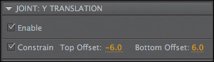
Constraining the translation of joints
In real life, joints only allow rotation of bones. However, in Animate CC, you can allow joints to actually slide in either the x (horizontal) or the y (vertical) direction, and set the limits on how far those joints can travel.
In this example, you’ll allow the joint in the pelvis to move up and down. This will give the armature some degree of motion so you can create a slight bobbing action.
1. If it’s not already selected, click the same bone that you selected to constrain rotation in the previous task.
2. In the Properties panel, select Enable in the Joint: Y Translation section.

Arrows appear from the joint, indicating that the joint can travel in the up and down directions.

3. Select the Constrain option in the Joint: Y Translation section of the Properties panel.
The arrowheads on the joint turn into T-shapes (straight lines), indicating that the translation is limited.
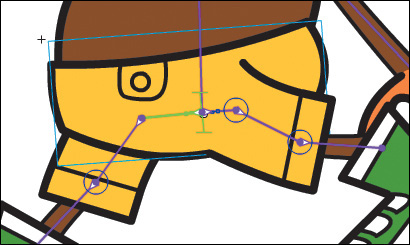
4. Set Top Offset to –6 and Bottom Offset to 6.
The bars on the joint shorten to indicate how much translation in the y direction the pelvis can do.
5. Grab the pelvis of the monkey and try to move it around.
The constraints on joint rotation and joint translation impose limits on the poses that help you create more realistic animations. The pelvis can now move slightly up and down as well as rock back and forth in a limited fashion.
Using on-Stage controls for joint constraints


Adding Poses
Your armature is now ready. You’ve connected your bones and made the appropriate constraints to make it easier to pose. In the Timeline, you insert poses just as you would insert keyframes for a motion tween.
Inserting poses
Recall that your goal is to define four unique poses that will allow a natural walk cycle.
1. On the Timeline, select frame 10 and choose Insert > Timeline > Keyframe, or right-click and choose Insert Pose.
![]() Note
Note
When dealing with armature layers, “poses” and “keyframes” are essentially the same thing.
A new pose/keyframe is inserted at frame 10. The pose in the first keyframe is copied and pasted into the second keyframe.

2. Move the arms and legs of your monkey armature so they are passing each other. The leg that is moving forward should have his knee rising and feet off the ground.

3. On the Timeline, select frame 20 and insert a third keyframe.
4. Move the arms and legs of your monkey armature so now the left leg and right arm are forward and the right leg and left arm are back, the opposite of the pose in frame 1.

5. Add a fourth keyframe/pose in frame 30 with the legs and arms passing each other.
6. Select frame 40 and insert additional frames to extend the Timeline.
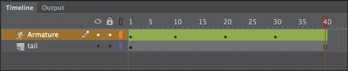
7. Hold down the Alt/Option key and drag the first keyframe (in frame 1) to frame 40.
The keyframe containing the pose in frame 1 is duplicated in keyframe 40. Now that first and last keyframes are identical, the animation can loop seamlessly.

8. The first four keyframes should look similar to this figure, but feel free to experiment and give your monkey a personality of its own! Getting his feet, arms, and body coordinated may take a lot of little adjustments and refinements.

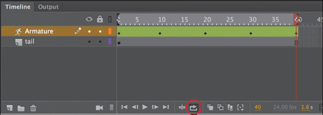
9. Select Loop Playback at the bottom of the Timeline (Shift+Alt+L/Shift+Option+L) and extend the markers to cover the entire animation span from frame 1 to frame 40.
![]() Tip
Tip
You can edit poses on the Timeline just as you can with keyframes of a motion tween. Right-click along the Timeline and choose Insert Pose to insert a new pose. Right-click any pose and select Clear Pose to remove the pose from the layer. Ctrl-click/Command-click a pose to select it. Drag the pose to move it to a different position along the Timeline.
10. Click the Play button at the bottom of the Timeline (Enter/Return key) to view your animation loop.
The animation won’t be perfect, but you can see, once your armature is complete, how easy and fun it is to create different poses and natural, complex motions.
![]() Tip
Tip
You can add eases to your inverse kinematics animations by selecting the animation on the Timeline and choosing an Ease Type and Strength in the Properties panel. Eases can change the animation by starting slowly (ease-in) or by ending gradually (ease-out).
![]() Tip
Tip
Add more nuance to your walk cycle to create even more realism! Tilt the monkey’s head just slightly in some of the poses and see how a little head bob can make his walk a little more natural.
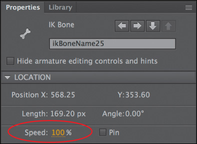
Changing joint speed
Inverse Kinematics with Shapes
The monkey is an armature made with various movie clip symbols. You can also create armatures with shapes, which are useful for animating objects without obvious joints and segments but can still have an articulated motion. For example, the arms of an octopus have no actual joints, but you can add bones to a smooth tentacle to animate its undulating motion. You can also animate other organic objects such as a snake, a waving flag, leaves of grass bending in the wind, or in the next task, a monkey’s tail.
Defining bones inside a shape
You’ll create a tail, add a series of bones to it, animate it curling and unfurling, and add it to your monkey walk cycle.
1. Choose Insert > New Symbol (Ctrl+F8/Command+F8). In the Create New Symbol dialog box, choose Movie Clip for the symbol and enter monkey_tail for the symbol name.
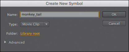
2. Click OK.
Animate creates a new symbol and puts you into symbol-editing mode for that symbol.
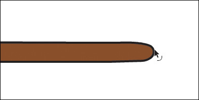
3. Select the Rectangle tool.
4. Select a light brown fill color (#8B4B0E) and a 2 point black stroke, and create a long, thin rectangle about 350 pixels wide and 20 pixels tall.

5. Select the Selection tool and reshape the right end of the rectangle to create a smooth, rounded end for the monkey’s tail.
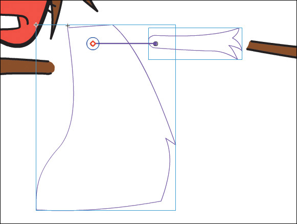
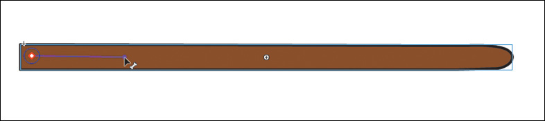
6. Select the Bone tool.
7. Click inside the rectangular shape starting from the left side, and drag a bone inside the tail just a fraction of the way.
Animate creates an armature of your rectangular shape and moves it to its own Armature layer.
8. Click the end of the first bone and drag out the next bone a little farther down toward the tip of the tail.

The second bone is defined.
9. Continue building the tail armature with a total of six or seven bones.
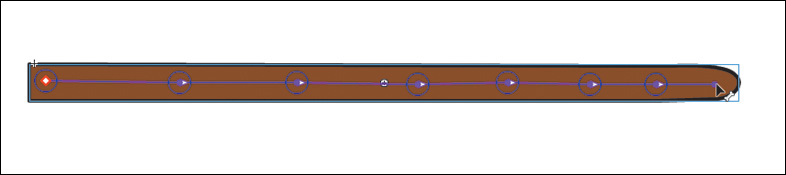
10. When the armature is complete, use the Selection tool to drag the last bone to see how the deformation of the tail follows the bones of the armature.
Animating the tail
Animating an armature within a shape follows the same process as animating an armature build with movie clips. You establish different poses for your armature with keyframes along the Timeline.
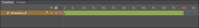
1. Select frame 60 on the Timeline in the monkey_tail movie clip symbol and choose Insert > Timeline > Frames (F5).
Animate adds frames up to frame 60 on the Timeline.
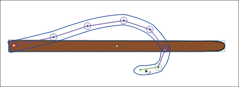
2. In the first frame, move your monkey tail armature so the tip of the tail lies flat on the ground.

3. Select frame 20.
4. Choose Insert > Timeline > Keyframe (F6).
Animate inserts a new keyframe at frame 20 with the same pose that is in frame 1.

5. Select frame 30.
6. Move the armature so the monkey’s tail curls upward.

Animate automatically inserts a keyframe at frame 30 with the new pose. The monkey’s tail remains flat from frames 1 through 20. After frame 20, the tail will begin to curl until it reaches the pose at frame 30.
7. Select frame 50 and insert a new keyframe (F6).
8. Click to select the keyframe in frame 1. Hold down the Alt/Option key and drag the keyframe in frame 1 to frame 60.
Animate duplicates the first keyframe to frame 60. Your Timeline should now have five keyframes. The first, second, and fifth keyframes should have the tail flat. The third and fourth keyframes should have the tail curled.

9. Play the animation as a loop.
The monkey’s tail curls and unfurls repeatedly across 60 frames.
Combining the tail and the walk cycle
Since the tail animation plays longer than the monkey walk cycle (which is 40 frames), when you combine the animations, the movements won’t be in synchrony, providing a less regular, and more organic, cycle.
1. Return to the main Stage.
2. Rename the empty layer tail and make sure it’s under the Armature layer. Add enough frames in the tail layer to match the walk cycle (40 frames).
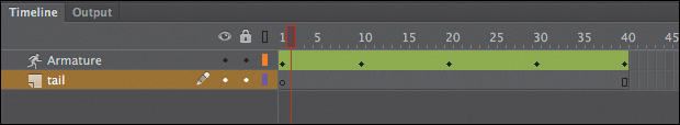
3. Drag an instance of the monkey_tail movie clip symbol from the library to the Stage, placing the base of the tail behind the monkey’s body.
4. Test your animation (Control > Test Movie > In Browser).
Animate exports the necessary files to play the animation with HTML and JavaScript in a browser. The monkey walks continuously while the movie clip animation of his tail curls.
Editing the shape
You don’t need any special tools to edit a shape that contains bones. Many of the same drawing and editing tools in the Tools panel, such as the Paint Bucket, the Ink Bottle, and the Subselection tools, are available to you to edit the fill, the stroke, or the contours.
1. Use the Paint Bucket tool to change the fill color of an armature shape.
2. Use the Ink Bottle tool to change the stroke color or style of an armature shape.
3. Select the Subselection tool and click the outline of the armature shape. The anchor points and the control handles appear around the contour of the shape, allowing you to drag the anchor points to new locations or drag the handles to change the curvatures.

4. Select the Add Anchor Point tool and click the outline of the armature shape to add new anchor points.
5. Select the Delete Anchor Point tool and click the outline of the armature shape to remove anchor points.
![]() Note
Note
The organic control of a shape by its armature is a result of a mapping between the anchor points along the shapes and its bones. You can edit the connections between the bones and their control points and refine the behavior with the Bind tool. The Bind tool is grouped under the Bone tool. Consult the Animate Help documentation for more information on how to use this advanced tool.
Adding the background
Your monkey stays in one spot on the Stage, so to make the illusion complete, add a scrolling background to make it seem like he’s really taking a stroll.
1. Insert a new layer on the main Timeline and name it background.
2. Move the new background layer to the bottom of the other layers.

3. A scrolling background movie clip is already provided in the library. The movie clip is called background, and it depicts a sidewalk moving from left to right by using shape tweens of line segments.

4. Drag an instance of the background movie clip on the Stage into the bottom layer. Place the instance approximately at x=-170 and y=620.

5. Choose Test > Movie > In Browser.
Animate opens your browser to display your movie. Your monkey animation is complete!

Simulating Physics with Springiness
So far, you’ve seen how armatures can help you easily pose your characters and objects in different keyframes to create smooth, natural motion. But you can also add a bit of physics to your armatures so they react to how they move from pose to pose. The Spring feature helps you do this easily.
Spring simulates physics in any animated armature, whether you’re using movie clips or a shape. A flexible object normally would have some “springiness” that would cause it to jiggle on its own as it moves, and continue to jiggle even after motion of the entire body stops. The amount of springiness depends on the object—for example, a dangling rope would have a lot of jiggle, but a diving board would be much stiffer and have less jiggle. You can set the strength of the spring depending on your object, and you can even set different springiness amounts for each bone in an armature to help you get the exact amount of rigidity or flexibility in your animation. In a tree, for example, the larger branches will be less springy than the smaller, end branches.
Define bones for your armature
In the following steps, you’ll animate a leaf being blown by the wind. The first step for any inverse kinematics animation is to build the armature with the Bone tool.
1. Open the file 07_IK_spring_start.fla.
2. On the Stage you will see a simple shape of a leaf and its stem.

3. Select the Bone tool.
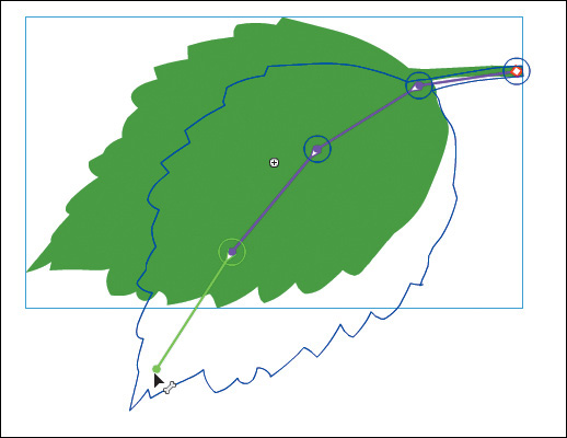
4. Click inside the leaf shape starting in the base of the stem and drag the first bone to the base of the leaf.

The first bone is defined. The contents of the current layer are separated to a new Armature layer.
5. Click the end of the first bone and drag out the next bone a little farther down the leaf.
6. Continue creating more bones to extend the armature to the tip of the leaf. Your completed armature should have about four bones.

Setting the spring strength for each bone
Next, you’ll set the strength value for the spring for each bone. The strength value can range from 0 (no spring) to 100 (maximum spring).
1. Select the last bone (at the tip of the leaf) of the armature.

2. In the Properties panel, in the Spring section, enter 100 for the Strength.
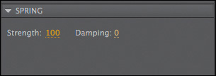
The last bone has the maximum spring strength since the tip is the most flexible part of the whole armature and would have the most independent motion.
3. Select the next bone in the armature. You can simply click it on the Stage or you can navigate up the armature hierarchy with the arrows in the Properties panel.

4. In the Properties panel, in the Spring section, enter 80 for the Strength.

The middle of the leaf is a little less flexible than the tip, so it has a smaller strength value.
5. Select the next adjacent bone, and in the Properties panel, in the Spring section, enter 60 for the Strength.
The base of the leaf is even less flexible than the middle, so it has an even smaller strength value.
Insert the next pose
Next, you’ll create a new pose of the leaf in a downward position and Animate will use the spring values to add wiggling, fluttering, and other internal motions.
1. Select frame 90 on the Timeline and choose Insert > Timeline > Frame (F5) to add frames to the Timeline.
2. Select frame 20 of the Armature layer, which contains your leaf.
3. Grab the bone at the tip of the leaf and pull it downward as if the wind blew on the leaf.
A new pose is created in frame 20.
4. Return the playhead to frame one and play the animation (Enter/Return key).
The leaf moves downward from the first pose to the second, but even past the second keyframe, the leaf continues to bend and sway slightly. The back and forth rotation of the leaf armature, combined with the addition of springiness to the bones, simulates the responses to physical forces within an actual leaf stem and makes the animation more realistic. Features like Spring and Damping (which you’ll learn about next) make it much simpler to animate complicated natural motions in Animate.
![]() Note
Note
The effects of the Spring feature are more apparent when there are additional frames on the Timeline after the armature’s final pose, as in this lesson. The additional frames allow you to see the residual bouncing effect after the last pose.
Adding damping effects
Damping refers to how much the spring effect decreases with time. It wouldn’t be realistic if the swaying of the leaf continues indefinitely. Over time, the swaying should lessen and eventually stop. You can set a Damping value for each bone from 0 (no damping) to 100 (maximum damping) to control how rapidly these effects diminish.
1. Select the last bone of the leaf (at the tip), and in the Properties panel, in the Spring section, enter 50 for the Damping value.

The Damping value will decrease the rocking of the leaf over time.
2. Select the next bone in the armature (in the middle of the leaf) and in the Properties panel, enter the maximum value (100) for Damping.
3. Select the next bone in the armature (at the base of the leaf) and in the Properties panel, enter the maximum value (100) for Damping.
4. Choose Control > Test Movie > In Animate to see the effects that the Damping values have on the motion of your leaf.
The leaf still sways, but the motion quickly subsides. The Damping values help add a sense of weight to the armature. Experiment with both the Strength and Damping values in the Spring section of your armature to get the most realistic motion.
Review Questions
1. What are the two ways of using the Bone tool?
2. Define and differentiate these terms: a bone, a joint, and an armature.
3. What is the hierarchy of the armature?
4. How do you constrain or disable the rotation of joints?
5. What do strength and damping refer to in the Spring feature?
Review Answers
1. The Bone tool can connect movie clip instances together to form an articulated object that can be posed and animated with inverse kinematics. The Bone tool can also create an armature within a shape, which can be posed and animated with inverse kinematics as well.
2. Bones are the objects that connect individual movie clips together or that make up the internal structure of a shape for motion with inverse kinematics. Joints are the articulations between bones. Joints can rotate as well as translate (slide in both the x and y directions). Armatures refer to the complete articulated object. Armatures are separated on their own special Armature layers on the Timeline where poses can be inserted for animation.
3. An armature is made up of bones that are ordered in a hierarchy. When a bone is connected to another, one is the parent and the other is the child. When a parent bone has many child bones, each child bone can be described as a sibling to each other.
4. Hold down the Shift key to temporarily disable the motion of the armature and isolate a single bone’s rotation. Use the Properties panel to pin a bone to prevent it from rotating, or deselect the Enable option in the Rotation section of the Properties panel to disable a particular joint’s rotation.
5. Strength is the amount of springiness of any individual bone in an armature. Add springiness with the Spring feature to simulate the way different parts of a flexible object jiggle when the entire object moves and continue to jiggle when the object stops. Damping refers to how quickly the springiness effect subsides over time.