
The essence of animation is change. Flash has always offered numerous ways to change an object’s size, color, position, orientation, and other characteristics. A new addition to Flash CS4 is the ability to transform objects in 3D space, which you’ll learn about in #16.
This chapter also covers techniques that make working with objects easier, such as simplifying them, grouping them, and placing them on different layers. Getting familiar with these nuts-and-bolts procedures will provide a solid foundation for the creative work you do in Flash.
You already know that the Selection tool (the black arrow) is used to select an entire path, and the Subselection tool (the white arrow) is used to select individual anchor points within a path. Now it’s time to get more specific. Here are other ways in which you might use selection tools:
• Selecting more than one path. Drag the Selection tool to outline a rectangular area on the stage. When you release the mouse button, any paths within that area are selected. If a path is partly inside and partly outside the rectangular area, only the inside portion is selected.
• Selecting more than one path on a crowded stage. You can use the Lasso tool to outline an irregularly shaped area surrounding the paths that you want to select. When you release the mouse button, any paths that are within that irregular area are selected (Figure 14a). If a path is partly inside and partly outside the area, only the inside portion will be selected.

• Selecting more than one anchor point. Drag the Subselection tool to outline a rectangular area on the stage. When you release the mouse button, any anchor points within that area are selected, regardless of whether they belong to one path or several.
Tip
To select only one anchor point, draw a rectangle around it with the Subselection tool. Doing so is often easier than trying to click directly on the point.
• Adding to an existing selection. If one or more paths or anchor points are already selected, hold down the Shift key while clicking additional paths (with the Selection tool) or anchor points (with the Subselection tool). Those paths or anchor points will be added to the selection.
• Subtracting from an existing selection. If multiple paths are already selected, hold down the Shift key while you use the Selection tool to click each path that you want to subtract.
• Selecting everything. Use the Selection tool to draw a rectangle around the entire stage, or choose Edit > Select All.
• Deselecting everything. Use any of the selection tools to click an empty area of the stage, or choose Edit > Deselect All.
Transforming an object means changing its position, orientation, or proportions. Paths, groups (see #17), and symbol instances (see #23) can be transformed using the Free Transform tool.
You can use any of the methods described in #14 to select the objects that you want to transform. Alternatively, you can select objects directly with the Free Transform tool, either by clicking them or stretching a rectangle around them.
When you click the Free Transform tool in the Tools panel, any currently selected objects become framed by a black rectangle. The rectangle has eight black squares (or handles) around its perimeter—four at the corners, and four midway between them—that you can use to perform the transformations (Figure 15a).
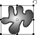
You can transform the selected object or objects in several ways:
• Scaling. Position your pointer directly on any of the eight handles. The pointer becomes a vertical, horizontal, or diagonal double-headed arrow. Depending on the orientation of the arrow, you can drag a particular handle vertically, horizontally, or both. (The top and bottom center handles adjust height, while the left and right center handles adjust width; the corner handles can adjust both dimensions at once.) To scale the object without changing its ratio of width to height, hold down the Shift key while dragging a corner handle.
• Rotation. The white circle in the center of the rectangle is called the transformation point; it’s the point around which the rotation will occur. (Think of it as a pushpin in the middle of a sheet of paper.) If you want to rotate the object around some point other than the center, move the transformation point to the desired spot. Then place your pointer a few pixels outward from any of the corner handles. The pointer becomes a curved, double-headed arrow, indicating that you can now rotate the object by dragging clockwise or counterclockwise.
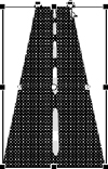
• Skewing. Skewing an object means changing the angles at the corners of the selection rectangle, making one pair of angles narrower and one pair wider, while keeping the sides of the rectangle parallel to each other. (The same transformation is called shearing in Adobe Illustrator.) Place your pointer on the perimeter of the selection rectangle, midway between any two handles. The pointer turns into two overlapping half-arrows, indicating that you can now skew the object by dragging along the axis indicated by the arrows.
• Distortion. Distorting an object means moving each of its corner handles independently of the others. You can do this by holding down the Control key (Windows) or Command key (Mac) while dragging each corner handle individually. For a perspective distortion effect, do the same thing while holding down the Shift and Control keys (Windows) or Shift and Command keys (Mac) (Figure 15b).
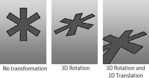
3D effects are being used with increasing frequency in illustration and animation. In recent years, Adobe has added 3D capabilities to Photoshop and Illustrator; now it’s begun to add them to Flash as well.
There are two 3D tools: the 3D Rotation tool, which is initially visible on the Tools panel, and the 3D Translation tool, which is hidden beneath it. These tools can be used only on Movie Clip symbols (see #28), and only in FLA files that were created using the ActionScript 3.0 option (see #1).
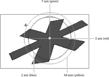
3D transformations take place in relation to three axes labeled X, Y, and Z. The X and Y axes are the familiar ones; they correspond to the horizontal and vertical dimensions. For the Z axis, imagine a line that’s oriented with one end toward you and the other end away from you (Figure 16a). This is the axis that adds depth.
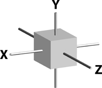
When you select a suitable object and choose a 3D tool, Flash places the center of the object at the intersection of the three axes. The 3D Rotation tool allows you to turn the object around one or more of the axes, changing its orientation. The 3D Translation tool allows you to relocate the object in 3D space, moving it closer or farther away in any direction (Figure 16b).
You use both 3D tools the same way: Select the object you want to transform and choose the desired tool. Lines appear on the stage representing the three axes: red for X, green for Y, and blue for Z. Drag along any of the axes to turn or move the selected object in the corresponding direction.
The Z axis is the most challenging, since it can’t be represented accurately as a straight line. The 3D Rotation tool displays it as a blue circle; dragging around the circle changes the angle of rotation (Figure 16c). The 3D Translation tool displays it as a blue dot; dragging the dot causes the object to move forward or backward.
One important difference between the 3D Translation tool and the 3D Rotation tool is that the former calculates positions relative to the stage, while the latter calculates positions relative to an arbitrary location in space called the 3D center point. By default, the 3D center point is in the middle of the stage, but you can drag it anywhere you like.
Whenever a 3D object is selected, you have access to 3D Position and View controls in the Properties panel. Unlike the 3D Translation and 3D Rotation tools, which move the 3D object in space, these controls allow you to change the perspective from which you’re looking at the object—the equivalent of relocating the stage in 3D space. As with most numerical controls in Flash, the easiest way to use these is to drag left or right across the numbers to make them decrease or increase.
In #7 you found out how two identically colored fills can merge if they’re allowed to overlap. Combining multiple objects into a single object is often desirable, but the problem with that method of merging paths is that it isn’t reversible. When two or more paths are turned into one, they permanently lose their identities as separate objects.
There are many occasions when you want to treat several objects as a single unit—for convenience in selecting them, for example—but want to retain the option to separate them again. In these situations, grouping is the answer.
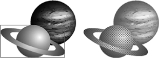
To combine any number of objects into a single group, select them all and choose Modify > Group. Grouping the objects doesn’t change their appearance, but it does allow them to be selected with a single click (Figure 17a).

A group doesn’t behave like a path. Selecting a group and trying to change its fill color or stroke weight doesn’t work. But if keeping the objects grouped becomes inconvenient, you can easily reverse the process by choosing Modify > Ungroup. All of the formerly grouped objects regain their independent identities, and they can once again be edited or transformed individually.
Often, you’ll want to modify an object within a group, but you won’t want to go through the trouble of ungrouping, making the modifications, and then grouping again. In such cases, you can edit objects within a group without ungrouping them.
To do this, choose the Selection tool and double-click the group on the stage. Some odd things occur: The paths within the group now sport dot screens to indicate that they’re selected and editable, and everything else on the stage becomes dim (Figure 17b). What’s happened is that Flash has entered group-editing mode. Think of it as an alternate universe where the group is the only thing that exists.
To confirm that Flash is in group-editing mode, look at the narrow divider between the timeline and the stage. You’ll see the phrase Scene 1 on the left, and the word Group just to the right (Figure 17c). These words represent a type of navigation known as a breadcrumb trail. Each time you move from a wider environment to a narrower environment—for example, from the main stage, to the interior of a group, to a symbol inside the group—your progress is charted from left to right on the breadcrumb trail.
While you’re in group-editing mode, you can make whatever changes you want to the objects in the group. Then, to find your way back to where you came from, you follow the trail in reverse—that is, from right to left. In this case, if you want to exit group-editing mode, you can click the phrase Scene 1 (which represents the movie as a whole). The word Group disappears from the end of the breadcrumb trail, the group once again acts like a group, and all of the other objects on the stage become accessible again.
Knowing how to follow the breadcrumb trail will become even more important when we get to #24, “Editing Symbols.”
Keeping the size of a Flash file as small as possible is crucial, because the effectiveness of a SWF file depends partly on how quickly it can be downloaded from the Web.
“The fewer the anchor points, the smaller the file” is a good rule of thumb in working with vector graphics. If you can get rid of unnecessary anchor points, your animation will look better and play more snappily.
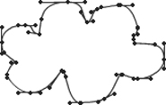
When you work with the shape tools and shape primitives, extraneous anchor points are not a problem. But when you use tools such as the Pencil or Brush, you’re likely to have many more anchor points than you need (Figure 18a). Every time your hand-drawn path jiggles or changes direction slightly, Flash creates another anchor point. Even if you use the Pen tool, you’re often tempted to put in extra anchor points because it’s easier than making smooth curves.
There are several ways to reduce the number of anchor points in a path:
• Delete the anchor points manually. If you’re comfortable working with Smooth Curve points, Corner points, and direction lines, you can look for unnecessary anchor points in your path and use the Delete Anchor Point tool to remove them. Doing so is time-consuming, but it gives you full control over the appearance of your paths.
• Smooth your path. You saw in #9 and #11 that the Smoothing control in Properties can make hand-drawn paths look much cleaner. In most cases, Flash removes unnecessary anchor points as part of the smoothing process. A smoothed path not only looks better; it also yields a smaller file size.
If you didn’t use the Smoothing option when you first created your path, you still have an opportunity. Select the path with the Selection tool, and then click the Smooth icon in the options area of the Tools panel (Figure 18b). You can click this icon repeatedly, and each time you do, the path gets a little smoother. (Another way to do the same thing is to select Modify > Shape > Smooth; you can do that repeatedly as well.)

• Optimize your path. The automated way to simplify a path is to select the path and then choose Modify > Shape > Optimize. The resulting dialog box allows you to choose a degree of smoothing from 0 to 100. As you change the amount of smoothing, you can preview the result on the stage. When you click OK, Flash does the optimization and reports how many curves—which essentially means anchor points—were eliminated.
Most of your Flash movies will contain text of one kind or another. If you’ve ever used a word processor, you should be comfortable with the way Flash handles text.
To add text to the stage, select the Text tool from the Tools panel. The Properties panel fills up with options, the most important of which is the Text Type menu at the top. Make sure the menu says Static Text. (The other options—Dynamic Text and Input Text—are only for specialized ActionScript applications.)
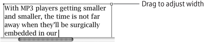
Use the Text tool to drag a rectangle across the stage. Make the rectangle as wide as you want your text block to be, but remember that you can adjust the width at any time by dragging the white square on the upper right of the rectangle (Figure 19a). A blinking cursor appears inside the rectangle, indicating that Flash is ready to accept your text entry.
When you include text in a Flash movie, it’s important to understand how Flash handles fonts. You can use a particular font in your movie only if that font is installed on the computer you’re using. When you test or publish your movie, a subset of the font is automatically embedded in the SWF file, so anyone who watches the movie will see the text in the correct font and size. However, no font information is embedded in a FLA file. If you give your FLA file to colleagues or clients, be sure their computers have the necessary fonts installed. Otherwise, they’ll be prompted to choose replacement fonts when they open the FLA file.
Anti-aliasing is the process used by Flash and other programs to make text and images look smoother on the screen. The Properties panel includes a Font Rendering Method menu that lets you set anti-aliasing options for each text field you create. If the text you’re creating is intended to be put into motion, you’ll generally want to choose Anti-Alias for Animation. If the text is intended to be static, you’ll get better results with Anti-Alias for Readability. If you use extremely small text, it will probably be most readable with no smoothing at all. In that case, you’d choose Bitmap Text (No Anti-Alias).
A block of text in Flash is known as a text object. As the name implies, it’s a self-contained unit. If you move, resize, or delete a text object, all of its text is affected.
Sometimes, however, you may not want your text to behave as a single object. For example, you may want to animate an explosion, scattering all the text randomly. To do this, you have to convert your text from a single object to many; in fact, every character needs to be a separate object.
The Break Apart command on the Modify menu is ideal for situations like this. As you’ll see in the next few chapters, Break Apart does different things in different situations. In this case, when applied to a text object that contains two or more characters, the Break Apart command automatically breaks each character into a separately selectable object (Figure 20a).

You can apply the Break Apart command a second time to the same text. Applying it once breaks the text object into individual characters; applying it a second time converts each character into an editable vector path. Using Break Apart in this way has advantages and drawbacks.
• Advantages. When text characters have been converted to standard vector shapes, the computer no longer needs to have a specific font installed in order to display the text. You can save your FLA file and pass it on to anyone else with assurance that your text will display correctly. Also, these converted text characters can now be edited like any other vector paths, allowing you to experiment with interesting typographical effects (Figure 20b).

• Drawbacks. Breaking text apart is irreversible; individual characters can’t be turned back into an editable text block. If you need to change the content, the spelling, the typeface, the anti-aliasing, or any other characteristic of the text, you’ll have to input it all over again. Also, converting each individual character to a freestanding vector path may add an excessive number of anchor points, bloating the file size.
Every new FLA file begins with a single layer. You can see it in the left column of the timeline, labeled Layer 1.
Practically speaking, you need only one layer to create a vector drawing. That’s because every time you create a new object, Flash stacks it on top of the previous objects in the same layer. The position of an object in relation to the others in the stack is known as its depth level.
To change the depth level of a particular object, use the commands under Modify > Arrange. For example, let’s say a cloud is behind a building, and you want it to be in front. You could accomplish this by selecting the cloud and choosing Modify > Arrange > Bring to Front (Figure 21a).
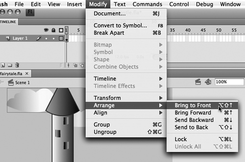
The other commands on the Arrange submenu are Bring Forward, which moves a selected item up one depth level at a time; Send Backward, which moves the item down one depth level at a time, and Send to Back, which moves the item to the lowest possible depth level.
Using the Modify > Arrange commands can be tedious, especially if you have many objects with many different depth levels on one layer. So you may choose to distribute your objects among different layers.
Unlike Photoshop and Illustrator, each of which has a dedicated Layers panel, Flash displays all of its layers in the timeline. To create a new layer in the timeline, click the Insert Layer icon (Figure 21b). Each new layer is numbered by default, but you can change a layer’s name by double-clicking the layer name and typing a new one.
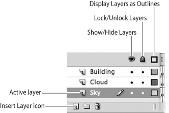
Once you have multiple layers in the timeline, you have to keep track of which layer is active at any given time. The active layer is highlighted in blue. Any object that you create is automatically placed on the active layer. If you want a new object to be on a different layer, you should first select your preferred layer in the timeline to make it active.
If an object is on one layer and you want to move it to another, you can select the object and choose Edit > Cut. Then select the layer to which you want the object to be moved and choose Edit > Paste in Place (if you want the object to have the same position on the stage as it did before) or Edit > Paste in Center (if you want the object to appear in the middle of the stage).
Layers that are higher up in the timeline appear in front of layers that are lower down. You can drag any layer up or down.
To the right of the layer names in the timeline are three columns that affect the way the objects in each layer are displayed. Each column has an On and an Off setting; you can toggle between the settings by clicking in the appropriate column and row.
The first column, with the eye icon at the top, controls the visibility of each layer. A dot in that column means that the corresponding layer is visible; a red X means that the corresponding layer is hidden.
The second column, with the padlock icon at the top, controls the security of each layer. A dot in that column means that the corresponding layer is unlocked; a padlock symbol means that the corresponding layer is locked. No objects can be copied from, pasted to, or edited on a locked layer.
The third column, with the empty square at the top, controls the display mode of each layer. A filled square in that column means that the layer is set to display strokes and fills; an empty square means that the layer is set to display only unadorned paths. If you have a slow computer, turning off the display of strokes and fills may make the screen refresh faster and thus speed up your work.
Clicking the icon at the top of each column turns the corresponding setting on or off for all the layers.