Before the introduction of Flash, most popular graphics programs were designed to create and edit bitmap graphics. A bitmap graphic (also known as a raster graphic or simply a bitmap) is made up of small squares called pixels.
Flash was one of the first popular programs to rely primarily on vector graphics instead of bitmaps. Vector graphics are essentially mathematical formulas that tell the computer what to draw. One of the innovations in Flash was a new set of tools that made creating vector graphics as simple and intuitive as creating bitmap graphics.
Since then, other programs such as Adobe Illustrator have further simplified the process of making vector graphics, but their tools often work differently from those in Flash. You need to become familiar with the unique ways in which Flash handles vector graphics.
The most basic element of a vector drawing is a path. A path can be defined as a series of anchor points connected by either straight lines or curves. Think of the anchor points as a skeleton that gives the path its structure; and think of the connecting lines or curves as skin stretched over the skeleton.
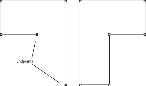
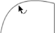
Paths can be open or closed. An open path has a beginning and end, marked by anchor points known as endpoints. A closed path completely encloses an area; it has no beginning and no end (Figure 6a). You create paths by using drawing tools such as the Pen tool, the Pencil tool, and the Brush tool, all of which you’ll learn about later in this chapter.
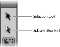
To do anything to an existing path—such as edit, move, or delete it—you must tell Flash which path you want to work with by selecting it with a tool. The two most important such tools are the Selection tool, represented by a black arrow, and the Subselection tool, represented by a white arrow (Figure 6b).
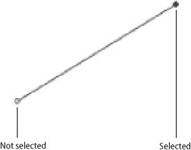
To use these tools, click the item you wish to select. The fundamental difference between them is that the Selection tool is used to select an entire path, while the Subselection tool is used for individual anchor points within a path. A selected anchor point is represented by a filled-in circle; an unselected anchor point is represented by a hollow circle (Figure 6c).
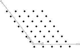
One of the innovations in Flash was allowing a user to work with vector paths without always having to pay attention to anchor points. For example, if you wanted to change a straight line into a curve in a traditional vector drawing program, you’d have to select the anchor points at each end of the curve and manipulate them. (You can still do this in Flash if you want to; you’ll see how when we look at the Pen tool in #12.) In Flash, however, you can turn a line into a curve simply by dragging a portion of the line outward with the Selection tool.
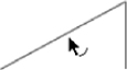
To do this, position the pointer anywhere between two anchor points. A small curve appears next to the pointer, alerting you that dragging from this point will reshape the line or curve (Figure 6d).
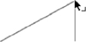
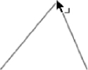
If you position the Selection tool over an anchor point, a small right angle appears next to the pointer (Figure 6e). This alerts you that dragging from this location will change the position of the anchor point itself, rather than reshaping the line or curve that connects two anchor points.
To use either of these techniques, you have to make sure the path that you want to edit isn’t currently selected. (To deselect a selected path, click somewhere outside it with the Selection tool.)
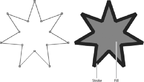
Strictly speaking, a path is a mathematical abstraction: Anchor points have no size, and the lines or curves that connect them have no thickness. To make a path visible, we have to give it either a stroke, a fill, or both.
A stroke is an outline, such as you might find in a paint-by-number set. A fill is what occupies the space enclosed by the stroke; it’s equivalent to the paint that you’d apply within the outlined areas. A stroke has both weight (thickness) and color; a fill has only color (Figure 7a).
Drawing tools handle strokes and fills in different ways; for example, the Pencil tool and the Line tool create only strokes, and the Brush tool creates only fills. Most other drawing tools are designed to create a stroke and a fill simultaneously.
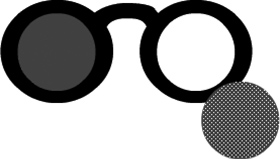
Even when a stroke and a fill are created at the same time with the same tool, Flash considers the stroke and the fill to be separate objects that can be selected and edited individually. To indicate that a stroke or fill has been selected, Flash covers it with a dot screen (Figure 7b).


Using the Selection tool to select strokes and fills requires that you remember various combinations of mouse clicks, most of which are unique to Flash:
• To select the portion of a stroke between the two nearest anchor points, single-click the portion of the stroke you want to select.
• To select an entire stroke, double-click anywhere on the stroke.
• To select a fill, single-click the fill.
• To select a path’s entire stroke and fill, double-click the fill.
• If a path has only a stroke and you want to add a fill, click the Paint Bucket tool on the Tools panel, and then click anywhere in the area enclosed by the stroke.
• If a path has only a fill and you want to add a stroke, click the Ink Bottle tool (hidden beneath the Paint Bucket on the Tools panel), and then click the fill.
Another interface feature that’s unique to Flash is the way strokes and fills interact with each other. When you select a path, move it so that it overlaps another path, and then deselect it, the following things happen:
• If two stroked paths overlap each other, a new anchor point forms at each place where the strokes intersect.
• If two filled paths overlap each other, the fills are exactly the same color, and the top path has no stroke, the two paths merge into a single path.
• If two filled paths overlap each other and the top fill has a stroke, the top path deletes the portion of the bottom path that’s directly beneath it. This occurs regardless of the color of the fills.
• If two filled paths overlap each other and the fills are different colors, the top path will delete the portion of the bottom path that’s directly beneath it. This occurs regardless whether the top fill has a stroke.
Once you get used to them, these interactions can be useful. For example, the ability of one fill to erase a differently colored fill beneath it makes it easy to cut a hole in a filled path, something that’s more difficult in a traditional vector drawing program such as Illustrator (Figure 7c).
There may be times, however, when you don’t want strokes or fills to interact in these ways. You can prevent these interactions by doing one of the following:
• Group each stroke or fill path individually before placing it on top of the other. (Grouping, which is a way of making several objects selectable as a single item, is covered in #17.) Although a group is designed to contain multiple objects, it’s perfectly okay for it to contain just one.
• Place each stroke or fill path on a separate layer. (Layers are covered in #21.)
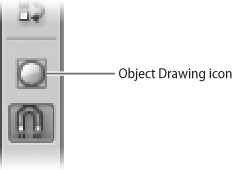
• Before creating each path, click the Object Drawing icon in the options area of the Tools panel (Figure 7d). Doing so causes the drawing tool to create a special type of path called a Drawing Object. Like the paths found in traditional vector programs, a Drawing Object has a stroke and fill that are inseparable.
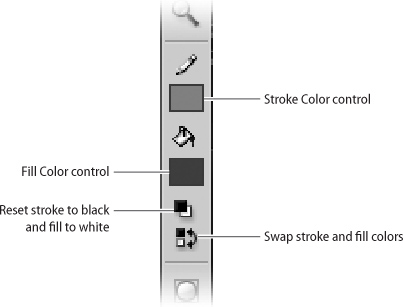
A stroke or fill, by definition, must have a color. To choose the color for a stroke, click the Stroke Color control on the Tools panel. To choose the color for a fill, click the Fill Color control (Figure 8a).
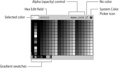
When you click the small rectangle on either color control, a pop-up window appears (Figure 8b). Within it, you can choose a color in any of the following ways:
• Click one of the color swatches.
• Delete the contents of the Hex Edit box and type in a hexadecimal color number.
• Click the System Color Picker icon, which produces a window displaying an assortment of color-selection controls. (These controls vary according to your computer’s operating system.)
Once you’ve selected a stroke or fill color, it will be applied to all subsequent paths you create, until you choose another color. (If any paths are selected when you choose a stroke or fill color, the new color is applied to them as well.)
Another way to choose stroke and fill colors is to use the Color panel (Figure 8c). (If it’s not part of your current workspace, choose Window > Color.) The upper left of the Color panel has color controls similar to those on the Tools panel, but the rest of the panel offers two color-selection tools not found elsewhere in Flash.
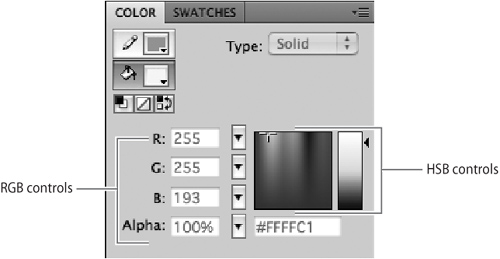
The first tool is a set of RGB sliders for mixing varying amounts of red, green, and blue to get the color you want. (Red, green, and blue are known as the additive primary colors. They can be combined to form any color your computer is capable of displaying.)
The second tool is a set of controls for specifying colors by hue, saturation, and brightness (HSB). To use them, choose a hue and saturation by clicking anywhere in the multicolored square. (Moving horizontally across the square changes the hue; moving up and down increases and decreases the saturation.) Then choose a brightness for the selected color by clicking anywhere in the vertical rectangle to the right of the square.
A final way to choose colors is to use the Eyedropper tool in the Tools panel. When you select the Eyedropper in the Tools panel and click a stroke, the Stroke Color controls in the Tools panel and Color panel display the color of the stroke you clicked. When you click a fill, the Fill Color controls change similarly.
A gradient is a series of colors that blend smoothly into one another. They’re often used to give flat objects the illusion of depth (Figure 8d). To create a gradient, you need at least two colors: a starting color and a destination color. (If you wish, you can add one or more intermediate colors.)
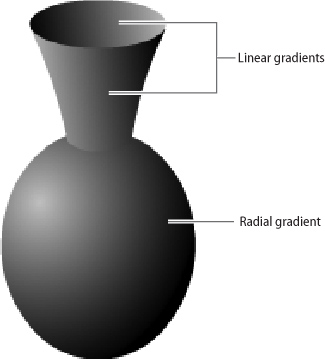
Flash supports two kinds of gradients: linear and radial. A linear gradient proceeds in a straight line from the starting color to the destination color; a radial gradient proceeds outward in a circular pattern, with the starting color at the center of the circle and the destination color at the edge.
The simplest way to create a gradient stroke or a gradient fill is to choose one of the gradient swatches from a pop-up window in the Stroke Color or Fill Color control. (See Figure 8b.)
In most cases, the simple black-and-white or primary-colored gradient that you choose from the window won’t suit your needs. You’ll want to modify the colors, or perhaps add some intermediate colors. You use the Color panel (Figure 8c) to do either.
If a gradient fill or stroke is currently selected, or either the Fill Color or Stroke Color control is currently set to a gradient, the Color panel displays that gradient. Otherwise, you can create a new gradient in the Color panel by choosing Linear or Radial from the Type menu (Figure 8e).
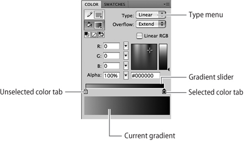
Initially, the gradient slider has two color tabs, one at each end, representing the starting and destination colors. (By default, the starting color is black and the destination color is white.) To change either of those colors, click the square part of the appropriate color tab and use any of the controls on the Color panel to choose a color for that tab. Alternatively, you can double-click the color tab and choose a color swatch from the pop-up menu.
To add a new color to a gradient, click the point in the gradient slider at which you want the new color to appear; an additional color tab will appear at that position. To delete a color from a gradient, drag its color tab away from the gradient slider. To change the position of any color, drag its color tab to the appropriate point along the gradient slider.
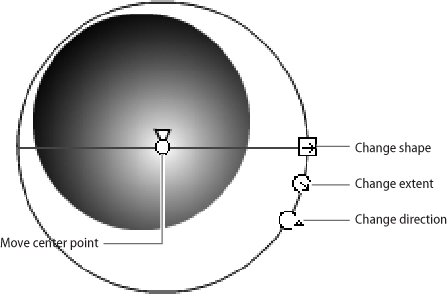
In many cases, you’ll not only want to customize your gradient; you’ll also want to change how the gradient is applied to a selected path. If so, choose the Gradient Transform tool from the Tools panel and click the stroke or fill that you want to change. (If the Gradient Transform tool isn’t visible in the Tools panel, hold down your mouse button over the Free Transform tool and choose Gradient Transform Tool from the menu that appears.)
When you click a stroke or path with the Gradient Transform tool, a set of controls appears around the gradient. For linear gradients, the controls allow you to change the extent and direction of the gradient; for radial gradients, the controls also allow you to change the shape and the center point of the gradient (Figure 8f).
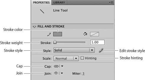
Option controls appear in the options area of the Tools panel and in the Properties panel (Figure 9a). If a tool is selected in the Tools panel, these controls affect how the tool operates; if an existing path is selected, these controls change the characteristics of that path.
Aside from the Stroke Color and Fill Color controls, these are the option controls you’re most likely to use regularly:
• Stroke weight. To adjust the weight (the heaviness or thickness) of a stroke, use the Stroke Weight controls in the Properties panel. You can type a number directly into the field, or you can choose a weight interactively by using the slider. Note that Flash isn’t consistent in its terminology; stroke weight is also called height or thickness in other parts of the program.
• Stroke style. A stroke can appear solid, dotted, or dashed; it can have a hand-drawn or painted look; it can be straight or wavy. To make basic adjustments to the style of a stroke, use the Stroke Style menu in Properties. To make more elaborate changes, click the Edit Stroke Style icon to the right of the menu. A dialog box appears in which you can separately adjust the type, pattern, wave height, and wave length of a stroke. (You can adjust the stroke weight—here called thickness—in the same dialog box.)
• Stroke caps and joins. The Cap and Join menus in Properties let you decide whether the ends of a stroke will be rounded, squared off, or unmodified. The Join menu applies to the points where two segments of a stroke meet: You can decide whether the corners will be mitered, rounded, or beveled (Figure 9b).


• Stroke hinting. Although the objects that you create with the drawing tools are vector objects, they are displayed on a computer screen as bitmaps. In some cases, a stroke may fall into gaps between pixels, making it appear faint or blurry on the screen. Selecting the Stroke Hinting check box on the Properties panel prevents this from happening.
• Smoothing. This control appears only for the tools that require free-hand drawing—that is, the Pencil and the Brush. Drawing smooth lines and curves is difficult even with a graphics tablet, but it’s almost impossible with more common input devices such as a mouse or trackball. Smoothing automatically makes a rough hand-drawn path more regular and gentle. The degree of smoothing can be set anywhere from 0 (no smoothing) to 100. Note that with the Brush tool, a high smoothing setting may distort the shape of the brushstroke, making it appear uneven.
• Snap to objects. This option is represented by a horseshoe-magnet icon in the options area of the Tools panel. If the icon is selected, it makes a path “magnetic,” meaning that the path will automatically try to line up with other objects when you drag and drop it. Other kinds of snapping (to a grid, for example) can be selected from the menu at View > Snapping.
Like all vector drawing programs, Flash offers a variety of shape tools such as ellipses and polygons. In most other programs, these simple shapes are called primitives, but Adobe reserves the term primitive objects for a particular type of shape whose characteristics can be changed dynamically by controls in the Properties panel.
Both the standard and primitive shape tools are listed in a single menu in the Tools panel. (You can see this menu by holding down your mouse button when the pointer is hovering over the Rectangle tool.) The standard shape tools available in that location are the Rectangle tool, the Oval tool, and the Polystar tool, the last of which can be used to create either polygons or stars. The primitive shape tools are Rectangle Primitive and the Oval Primitive; as of yet there is no Polystar Primitive tool.
To see the difference between these two types of tools, let’s look at the procedure for drawing a rectangle with rounded corners:
1. Select either the Rectangle or the Rectangle Primitive tool in the Tools panel. A set of option controls appears in Properties (Figure 10a).
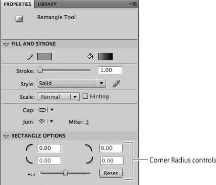
2. Set a Corner Radius value, either by typing it into the appropriate field in Properties or by using the slider. The higher the number, the more round the rectangle’s corners will be. (The default is for all the corners to be equally round, in which case you only have to enter one value. If you want the corners to have different degrees of roundness, click the lock icon and then enter a value in each of the four fields.)
3. Click and drag the mouse on the stage to draw the rectangle. The corners are automatically rounded to the degree you specified.
These steps are the same, regardless of whether you use the Rectangle or the Rectangle Primitive tool; but the resulting rectangles have several significant differences:
• Editability. Let’s say you don’t like the setting you used for the corners—you want them to be more rounded. If you drew the rectangle with the Rectangle tool, you can’t change the roundness of the corners; you have to delete the rectangle and draw it again with a new Corner Radius value. If you drew the rectangle with the Rectangle Primitive tool, you can simply enter a new value in Properties and see the corners change instantly.
• Flexibility. Let’s say you want to reshape the rectangle in some way, such as turning the straight sides into curves or cutting a hole in the middle of the fill. If you drew the rectangle with the Rectangle tool, you can do these kinds of things easily. If you drew the rectangle with the Rectangle Primitive tool, you can’t. The only characteristics of a primitive object that can be changed are those that are controlled from the Properties inspector, such as the object’s width, height, and location on the stage.
• Convertability. You can convert a primitive object to a drawing object by double-clicking it with the Selection tool and then choosing OK. The reverse is not true: You can’t convert any type of object into a primitive object.
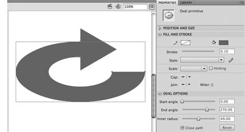
The Oval Primitive tool works like the Rectangle Primitive tool, except that it allows different characteristics to be set: The Start Angle and End Angle values allow you to create pie-shaped wedges (or pies with wedges cut out of them); and the Inner Radius setting allows you to create donut-shaped objects (Figure 10b).
Tip
To create a perfect square, hold down the Shift key while drawing a rectangle with the Rectangle tool or the Rectangle Primitive tool. Similarly, to create a perfect circle, hold down the Shift key while drawing an ellipse with the Oval tool or the Oval Primitive tool.
The shape tools, whether standard or primitive, can be handy for making things other than geometric shapes. In many cases, you’ll find that the easiest way to draw something is to start with a simple shape and modify it. For example, the vase in Figure 8d (see #8) is constructed entirely from two ellipses and a modified rectangle.
If you’re accustomed to drawing with pen or pencil on paper, you’ll find the Pencil tool to be intuitive. Simply select it in the Tools panel and draw with your mouse (or other input device). Depressing the mouse button creates a new path; releasing the mouse button ends the path.
The pencil line you’ve created is a standard vector path with a stroke applied. You can modify it in the same ways you’d modify any other path—for example, by changing the stroke’s weight or color, or by dragging anchor points with the Subselection tool.
When you select the Pencil tool in the Tools panel, a Pencil Mode menu appears in the options area (Figure 11a). The menu gives you three choices:
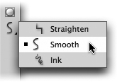
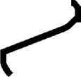
• Straighten. Select this option to convert a curved line into a series of straight-line segments. It also activates a shape-recognition feature that allows you to hand-draw smooth geometric shapes. For example, if you use the Pencil tool to draw a path that’s approximately oval-shaped, Flash will convert the path automatically to a perfect oval.
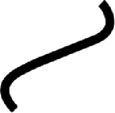
• Smooth. This setting leaves your path fundamentally as you drew it, but makes it smoother and more elegant. This is the option most people prefer: Instead of displaying the path you actually drew, it gives you the path you wanted to draw. The Smoothness control in the Properties panel (see #9) is available only when this option is selected.
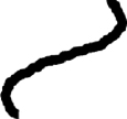
• Ink. If you want your path to appear exactly the way you drew it, use this option. Since most input devices (with the possible exception of a stylus and pressure-sensitive tablet) are ill-suited for drawing, you’re not likely to use this setting very often (Figure 11b).
The Pencil tool creates only strokes, without fills. (The Fill Color control is unavailable when the Pencil tool is selected.) If you create a closed path with the Pencil tool and then want to fill it, you can select the Paint Bucket tool and click in the enclosed area of the path.
The Pen may be the most unintuitive tool you’ll ever encounter. And if you’re willing to master it, you’ll also come to appreciate the degree of control that it provides. No other drawing tool can create lines and curves as precisely.
To draw with the Pen tool, there’s one basic rule you must remember: You can’t draw with the Pen tool. More specifically, you can’t use it in the way you’d expect, by dragging your mouse around the stage.
The Pen tool lets you create anchor points. As you create each new anchor point, Flash automatically connects it to the previous one with a line or curve. You can create three different kinds of anchor points with this tool (Figure 12a):
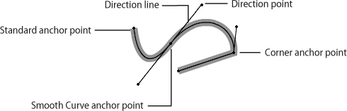
• Standard. To create a standard anchor point with the Pen tool, place the mouse pointer where you want the anchor point to be, and click—that is, press and immediately release the mouse button. If you then create another anchor point (by moving the pointer and clicking again), Flash connects it to the previous one with a straight line. By making several anchor points sequentially, you can create a path consisting of a series of line segments.
Tip
To end a path, click the Pen tool icon in the Tools panel after creating the last anchor point. When you make a new anchor point, Flash won’t connect it to the previous one.
• Smooth Curve. To create this kind of anchor point, press the mouse button, but don’t release it—instead, drag it outward. As you do so, you’ll see a pair of thin lines, called direction lines, extend outward from the anchor point. These direction lines distinguish a Smooth Curve anchor point from a standard anchor point. Each direction line is capped with a diamond-shaped handle called a direction point. When you create a second Smooth Curve anchor point, Flash automatically connects it to the previous one with a curve. You’ll find out later how to use direction points to control the shape and size of the curve.
• Corner. A Corner anchor point is the place where two curves—or a line and a curve—meet. It’s essentially two anchor points in one; that is, it presents one face to the anchor point before it and another face to the anchor point after it. A Corner point may be half standard anchor point and half Smooth Curve anchor point, or it may be a hybrid of two Smooth Curve anchor points. You can recognize a Corner point easily because it has only one direction line, or because it has two direction lines that point in different directions.
You can make a Corner point by modifying a Smooth Curve anchor point. To do so, choose the Subselection tool from the Tools panel. Then, while holding down the Alt key (Windows) or Option key (Mac), drag either of the two direction points that are attached to an existing Smooth Curve point. In doing so, you convert the Smooth Curve point (with two direction lines moving in tandem) to a Corner anchor point (with direction lines moving independently of one another). If you want one “face” of the Corner point to be a standard (non-curve) anchor point, use the Subselection tool to drag its direction point into the Corner point.
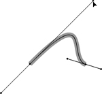
To change the size or shape of a curve—regardless of whether it passes through a Smooth Curve point or ends at a Corner point—simply drag its direction points. (Make sure to do this with the Subselection tool, not the Pen tool.) Each direction point acts like a magnet: When you move it away from the curve, the curve bends to follow it; when you move it toward the curve, the curve moves away from it (Figure 12b).
If you hold down the mouse button as the pointer is hovering over the Pen tool icon in the Tools panel, you’ll see a menu showing several related tools:
• Add Anchor Point. This tool allows you to add a new anchor point between any pair of existing anchor points.
• Delete Anchor Point. This tool allows you to delete any anchor point from an existing path.
• Convert Anchor Point. This tool allows you to convert a Smooth Curve point into a standard anchor point by clicking it. You can also convert a standard anchor point into a Smooth Curve point by dragging outward from the point.
Flash CS4 includes two new drawing tools: the Spray Brush and the Deco tool. They allow you to add effects to your animation that were not possible before.
The Spray Brush is hidden beneath the Brush tool. With its default settings, it works like a can of spray paint, scattering tiny dots in a random cloud. The Brush controls in the Properties panel let you change the size and angle of the cloud.
The standard stroke and fill colors have no effect on the Spray Brush. To change the color of the dots it sprays, use the pop-up color menu in Properties.
The Spray Brush isn’t limited to spraying dots; it can spray multiple copies of nearly anything you can create in Flash (Figure 13a). To make an object suitable for spraying, you have to convert it to a symbol (see #22). With the Spray Brush selected in the Tools panel, deselect the Default Shape check box in Properties. A dialog box appears, allowing you select the symbol that you want to spray.

The Deco tool allows you to fill large areas with decorative patterns. Its three effects—Vine Fill, Grid Fill, and Symmetry Brush—can be chosen from the Drawing Effects menu in Properties (Figure 13b).
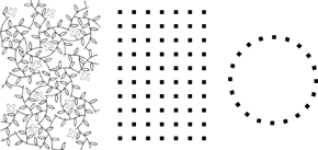
Vine Fill. This is the default effect. It causes a winding vine to grow outward from the pointer when you click the mouse. Press the Esc key to stop the growth; otherwise, the growth will stop automatically when the stage is filled. Controls in the Properties panel allow you to change the colors of the leaves and flowers, or to replace them with other symbols.
Grid Fill. This effect causes the Deco tool to fill the stage with an array of squares. You can change the color, size, and spacing of the squares, or substitute a symbol of your own.
Symmetry Brush. With this effect selected, you can use the Deco tool to make a variety of symmetrical patterns out of default squares or your own symbols. An Advanced Options menu allows you to choose what kind of symmetry you want—for example, Rotate Around (the default) creates a circular design, and Grid Translation creates a perspective effect.
Using the Symmetry Brush effect is tricky: Move the pointer to the stage and press—but don’t release—the mouse button. A light-green axis, or pair of axes, appears along with a preview of your pattern. Dragging the mouse pointer around the stage causes the pattern to change its size, angle, and frequency (Figure 13c). When it looks the way you want it to, release the mouse button.