


Customizing Virtual Application Patterns
This chapter describes the various interfaces that are available for customizing the virtual application patterns. There are two ways to create virtual application patterns: extend the available default patterns (Web Application Patterns) or create a plug-in and associate it with one or more pattern types, which are described in this chapter.
This chapter also describes different polices that can be attached to patterns to change the behavior of a deployed application.
The following topics are covered in this chapter:
6.1 Prerequisites
This section describes the requirements that are needed before virtual patterns are created or customized. For more information, see this website:
6.1.1 Hardware requirements
To use virtual application patterns, you must have the IBM PureApplication System W1500 hardware with the following software requirements:
•IBM PureApplication System W1500 V1.0.
•Configured NTP Server: Virtual machines that are provisioned as a part of a virtual pattern need an NTP server to set the system time.
6.1.2 Software requirements
The following requirements are necessary to start building new or customize existing patterns:
•IBM Foundation Pattern V2.0.0.3 or later (includes shared services). This pattern type is included with the product.
•Depending on the patterns you are using, there could be other requirements. For more information, see the Pure Application Information Center at this website:
http://pic.dhe.ibm.com/infocenter/psappsys/v1r0m0/topic/com.ibm.ipas.doc/iwd/apt_managepatterntypes.html
•To deploy a virtual application to the cloud environment, you must have one of the following roles or permissions:
– Workload resources administration role with permission to manage workload resources (full permission)
– Workload resources administration role with permission to view all workload resources (Read-only)
– Create patterns
– Create catalog content
– Create environment profiles
– IBM License Metric Tool user
6.2 Virtual Application Pattern elements
A virtual application pattern consists of plug-ins that define components, links, policies, and configuration files. By using virtual application patterns, components can be connected to show dependencies and policies that are attached during deployment to configure specific behavior.
6.2.1 Components
Components represent middleware services and are used as part of your pattern creation. Policies can be applied to these components to change the behavior of your pattern. You can create your own component as a part of creating virtual application pattern or use components that are provided by PureApplication System.
The following components are available in PureApplication System:
•Application:
– Other archive file (web application)
– Other archive file (Java application)
– Enterprise application component
– Existing Web Service Provider Endpoint
– Java application (IBM Java Runtime Version 7)
– Policy Set
– Web application component
•Database:
– Database Studio web console
– Database (DB2), such as IBM DB2
– Existing database (DB2)
– Existing database (Informix)
– Existing database (Oracle)
– Existing IMS database
•Messaging:
– Existing Messaging Service (WebSphere MQ)
– Topic
– Queue
•OSGi:
– Existing OSGi Bundle Repository (WebSphere Application Server)
– OSGi Application (WebSphere Application Server)
•Transaction processing:
– Existing CICS Transaction Gateway
– Existing IMS Transaction Manager
•User Registry:
– Existing User Registry (IBM Tivoli Directory Server)
– Existing User Registry (Microsoft Active Directory)
– User Registry (Tivoli Directory Server)
•Other Components:
– Connect Out
– Connect In
– “Connect in” (Java application)
– “Connect out” (Java application)
– Monitored file (Java application)
6.2.2 Policy types customization
Policies can be applied to virtual applications to attain specific behavior. For example, based on business criticality, some applications must be highly scalable and available. Policies can be applied to attain this goal. Figure 6-1 shows a sample web application pattern that is deployed. Figure 6-2 on page 271 and Figure 6-3 on page 272 show policy options that can be applied to this pattern.
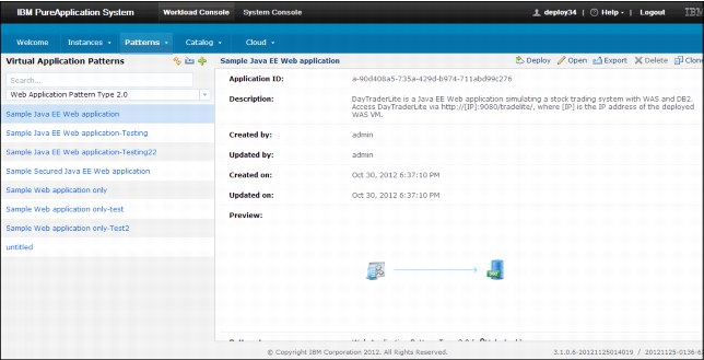
Figure 6-1 Sample Java EE web example
Scaling policy
A scaling policy is attached to a component to define the capability and conditions under which scaling activities are performed for your application.
The following attributes are available for a scaling policy:
•Session caching: Specifies whether to use session caching in your application.
•Scaling: There are several types of scaling, such as Static, CPU Based, Response Time Based, or Web to DB.
•Number of instances: Specifies the number of cluster members that are hosting the web application. The default value is 2, and an acceptable value range is 2 - 10. This attribute is required.
•Instance number, range of scaling in and out: Scaling range for instance members that host the web application. An acceptable value range is 1 - 50. This attribute is required.
•Minimum time (in seconds) to trigger an add or remove: Specifies the time duration condition to start the scaling activity. This attribute is required.
•Scaling in and out when CPU usage is out of threshold range (in percentage): Specifies the processor threshold condition that is necessary to start scaling activities. The platform is scaled after the processor usage exceeds the threshold range.
•Scaling in and out when web response time is out of the threshold range (in milliseconds): Specifies the web application response time condition necessary to start scaling activities. When the web application response time is out of this threshold range, your platform is scaled in or out. The acceptable values range 0 - 1,000 milliseconds.
•JDBC connections wait time is out of the threshold range (in milliseconds): Specifies the JDBC connection wait state that is necessary to start scaling activities. When the JDBC connections wait time is out of this threshold range, your platform is scaled in or out. The acceptable values range 0 - 10,000 milliseconds.
•JDBC connection pool usage is out of the threshold range (in percentage): Specifies JDBC connection pool usage necessary to start scaling activities. The platform is scaled after the threshold is exceeded.
Figure 6-2 shows the available scaling policy options.

Figure 6-2 Scaling policy options
Figure 6-3 shows the options to enable session cache.
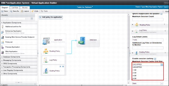
Figure 6-3 Options to enable session cache
Java virtual machine policy
A Java virtual machine policy controls the characteristics of the Java virtual machine.
A Java virtual machine policy features the following attributes:
•Minimum heap size: Specifies the minimum heap size of the Java virtual machine-specified size in megabytes (MB).
•Maximum heap size: Specifies the maximum heap size of the Java virtual machine-specified size in megabytes (MB).
•Enable debug: Specifies whether the Java virtual machine is in debug mode.
•Debug port: Specifies the port where the Java virtual machine listens for remote connections.
•Client (IP or IP/netmask): The IP address of the host that is used to debug.
•Client: Specifies an optional address of the debug client. This setting is used to restrict source access to the debug port. The value is an IP address, for example 1.2.3.4, or IP/netmask 1.2.0.0/255.255.0.0, which matches anything in the 1.2. network.
•Enable verbose garbage collection: Specifies whether the Java virtual machine has garbage collection enabled.
•Generic JVM arguments: More Java virtual machine arguments can be added to customize how Java virtual machine runs.
•Bit level: Specifies bit level as 32 bit or 64 bit, as shown in Figure 6-4.

Figure 6-4 Java virtual machine options: Bit level customization
Routing policy
The routing policy can be applied to the application component parts of your virtual application pattern. By using the routing policy, you can customize the context root for your component. You also can specify the protocol for your component.
A routing policy includes the following attributes:
•Virtual host name: Name of the virtual host for the routing policy. This attribute is required.
•HTTP: Specifies support for HTTP schema with a routing policy.
•HTTPS: Specifies support for HTTPS schema with a routing policy.
•Customize prefix for context root: Used to specify custom context root.
|
Important: The routing policy is automatically applied to a web application when there is a proxy shared service that is running in the same cloud group into which it is deployed. Otherwise, the routing policy is not automatically added to the virtual application.
When elastic load balancing is enabled, the combination of the context root, context root prefix, and virtual host name must be unique to successfully deploy multiple virtual application instances from a virtual application pattern. If you do not manually add a routing policy to a virtual application pattern, the autowiring capability of the elastic load balancing service automatically generates a unique prefix for each deployment.
When you manually add a routing policy to a virtual application pattern, the context prefix is optional. If you do not specify a context root ID, the virtual host name and context root are reserved by the elastic load balancing service. Therefore, if you try to deploy another virtual application instance with the same values, an error message is displayed to indicate that there is a reservation conflict. Stopping the virtual application instance that originally used these values does not release the reservation. You must delete the original virtual application instance to enable another deployment to use the same virtual host name and context root or specify a different context root before a new virtual application instance is deployed.
|
Figure 6-5 shows the available routing options to customize for routing your component.

Figure 6-5 Routing options
Logging
A log policy can be added to your application component part to specify configurations for logging.
A log policy features the following attributes:
•Log detail levels: Specifies the usage of log levels to control which events are processed by Java logging.
•Additional Log Files or Directories to Monitor: Specifies a semicolon-delimited list of directories or files to monitor. To specify that an entry is a directory, add a suffix to the entry with a slash, for example, /var/log/myApplication/, or add a prefix to it with a string, such as, dir:/var/log/myApplication. You can use an asterisk wildcard in the file-specification only, for example, /var/log/myApplication/*.log. By using the wildcard in the following manner, /var/log/*/my.log, is invalid. Any directory that is specified is visible in the Log Viewer.
Figure 6-6 shows different levels of logging that can be applied to your component.

Figure 6-6 Logging options
Figure 6-7 shows the deployment overview for the web application pattern.
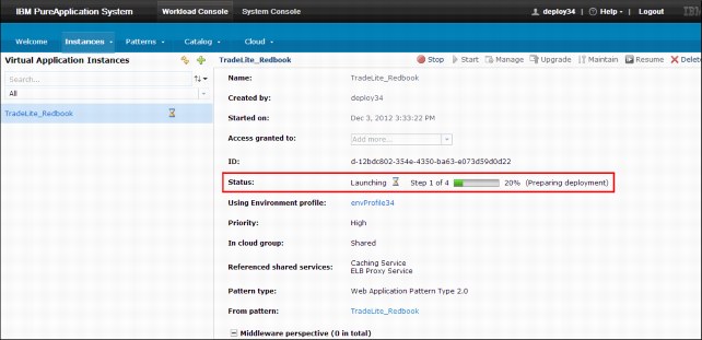
Figure 6-7 Deployment overview
Figure 6-8 shows the deployment process and virtual machine provisioning.

Figure 6-8 Virtual machine deployment
6.3 Creating virtual application patterns with the virtual application builder interface
Virtual application builder is the core to create a virtual application pattern. You can extend the functionality of default patterns that are provided by PureApplication System by using the following method:
•Editing virtual application pattern: By using the virtual application builder interface, you can edit existing preinstalled patterns to create your pattern and then deploy it. The following section shows how you can customize an existing pattern. Figure 6-9 shows the virtual application builder interface that is provided by PureApplication System.
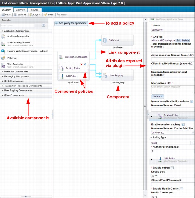
Figure 6-9 Virtual application builder
•Figure 6-10 shows an enterprise application component that is connected to a DB2 database component. It also shows a web application pattern, which has an application server and a database component that uses DB2.
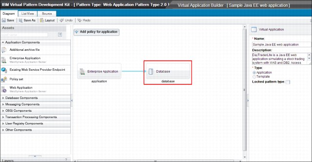
Figure 6-10 Generic Web Application pattern
By using the virtual application builder console, you can delete the DB2 component and add the Informix database component. This process is a simple drag with a link component connection. Figure 6-11 shows how the database is now changed to Informix and that the configuration of data sources is provided on the right side of the panel. You can select from the components that are listed to add into the palette by using the virtual application builder interface.

Figure 6-11 Database component replaced
6.4 Lifecycle management of virtual applications
A virtual application pattern is used to define and manage virtual applications. By using virtual applications, you define your application and non-functional requirements. The middleware that runs this application is addressed by the PureApplication System. Within your application, you define what policies are attached and the complete lifecycle of your application from inception through termination.
6.4.1 Virtual pattern development kit
The Virtual pattern development kit provides a development type virtual image of workload deployer and tooling that can be used to create custom virtual application patterns and deploy and test in this environment. The kit also includes web application and database pattern types, the IBM Image Construction and Composition Tool, the Plug-in Development Kit, and the Command Line tool. You can use this kit as a development or test platform to validate patterns and images before they are deployed.
When you are preparing to install the virtual pattern development kit, review the following link for a video demonstration that provides detailed information of how to install the kit:
A virtual application pattern consists of plug-ins that form the basis for creating virtual applications. Plug-ins are the core for virtual application patterns and are described next.
6.4.2 Plug-in overview
Plug-ins are used to define components, policies, and links. These plug-ins are used by virtual applications to create virtual application patterns. The IBM Workload Plugin Development Kit (PDK) allows developers to build their own plug-ins that are then deployed to the IBM PureApplication System.
Plug-ins consist of a package that includes the following configuration files and scripts.
•Contents of a Plug-in: Plug-ins consist of a configuration file, such as config.json. The following configuration and implementation extensions perform lifecycle management:
– config.json: Required configuration file.
– appmodel/metadata.json: Used to specify the components, links, and policies in the plug-in that are shown to users in the virtual application builder to build a model of a virtual application.
– appmodel/tweak.json and appmodel/operation.json: Used to change deployed virtual application instances from the deployment inlet in the system console.
– bundles/{name}.jar: The main file that contains the scanners, transformers, and provisioners of the plug-in.
– nodeparts/{name}.tgz: Artifacts that are installed by the activation script.
– parts/{name}.tgz: Extensions that are used to communicate with the system console about the lifecycle of a virtual application.
•Node parts, parts, and packages:
– Node parts are installed by the activation scripts. Node parts contain the setup.py and can install start.py or start.sh scripts before the workload agent is started.
– Parts contain scripts that manage the lifecycle of components by using roles. Roles are scripts that can be used by other scripts.
– Packages are a collection of both node parts and parts. Packages should have a unique name.
•Roles: Roles provide the lifecycle scripts for the management of software and applications. They offer event notifications between components. Each role is described in a topology document by a JSON object, which is contained within a corresponding VM template. Roles include the following states:
– INITIAL: Roles start in the initial state. The install.py script for each role is started and, based on the result, it is moved to the INSTALLED or the ERROR state.
– INSTALLED: The configure.py script runs during this state, if it exists.
– CONFIGURING: The start.py script runs during this state, if it exists.
– STARTING: The automatic state setting stops. A lifecycle script must explicitly set the role state to RUNNING.
– RUNNING: States the role the virtual machine is in.
– Topology document: The topology document is a JSON object and VM templates element. In the topology document, is a JSON array of VM template elements. Each element in the array represents a virtual machine to deploy. Components correspond to VM templates, and links correspond to links or dependencies between components.
6.4.3 Virtual application lifecycle
Plug-ins are the core for creation, deployment, and management of virtual applications. This section describes the lifecycle of a virtual application from its creation to final provision and deployment.
•Creating an application model
Virtual application builder is used to create or update virtual applications. You design a virtual application that is based on a virtual application pattern. This pattern is a collection of components, links, and policies. Virtual application builder scans for the artifacts to guide the modeling between components, links, and policies.
Figure 6-12 shows the application modeling process

Figure 6-12 Application process
•Deploying the application
Kernel services store the application model that is created by using the virtual application builder. When the virtual application is deployed to the target cloud, component transformation is started with link transformations. The kernel services convert the application model. The model is converted from logical description into a topology document or a physical description by using TopologyProvider and TopologyProcessor transformer implementation. TopologyProvider implementations are plug-in specific implementations that transform the application model into an unresolved topology. PureApplication System W1500 embeds Apache Velocity™ 1.6.2 as a template engine. Example 6-1 shows the sample transformer component and the corresponding TopologyProvider implementation it uses.
Example 6-1 Example for sample transformer component
<?xml version="1.0" encoding="UTF-8"?>
<scr:component xmlns:scr="http://www.osgi.org/xmlns/scr/v1.1.0" immediate="false" name="SingleServer">
<!-- implementation element determines whether trnasform is Java or Velocity template. -->
<implementation class="com.ibm.maestro.model.transform.template.TemplateTransformer"/>
<service>
<provide interface="com.ibm.maestro.model.transform.TopologyProvider"/>
</service>
<property name="component.template" type="String" value="templates/hello.vm"/>
</scr:component>
Figure 6-13 shows the deployment of an application.

Figure 6-13 Virtual application process deployment
After the plug-in is built and packaged into yourpluginame.tgz, you extract this file and the contents should resemble the contents that is shown in Figure 6-14.

Figure 6-14 Plug-in contents
The packaged plug-in file includes the following contents:
– The transformers and provisioners are in the bundles/{name}.jar file.
– The plug-in nodeparts/{name}.tgz file, which contains the node parts that are downloaded and installed with the activation script on the virtual machine.
– The parts/{name}.tgz file contains the parts that are downloaded and installed with the workload agent on the virtual machine.
•End to End Deployment Process of virtual application
Plug-ins use implementations of TopologyProvider that are provided by PureApplication System to convert instances of their components, links, and policies from the application model into an unresolved topology. The unresolved topology is generic. The transformers specify abstract package names rather than specific node parts or parts. The images and instance types are not yet specified.
After the unresolved topology document is complete, the next step resolves the specific node parts and parts, and images and instance types, according to cloud details and plug-in configuration, as specified in the config.json file. The resolved topology is passed to a provisioning phase where resources are provisioned from shared services. The final plug-in developer exit point is the post provisioner, which is started after all services are provisioned and after the topology document is finalized and written to the storehouse.
The topology document is written only once to the storehouse, and is never updated. A separate deployment document is written to the storehouse to represent the deployed virtual application. This deployment document is written and updated many times, and reflects the current state and status of the deployed virtual application. Example 6-2 on page 283 shows sample config.json, which includes parts and other information that are part of the package.
Example 6-2 Example description for config.json
{
"name" : "mywasplugin",
"version" : "1.0.0.1",
"files":[
"/PureApp_Examples/mytomcat-helloworld.war",
"/PureApp_Examples/apache-tomcat-7.0.34.tar.gz",
"/PureApp_Examples/ibm-java-sdk-6.0-12.0-linux-x86_64.bin"
],
"patterntypes" : {
"primary" : {
"ptype.firstEx" : "1.0"
}
},
"packages": {
"pkg1": [
{
"requires" : {
"arch" : "x86_64",
"memory": 128
},
"parts": [
{
"part": "parts/package_sample.tgz"
}
]
}
]
}
}
Deployment culminates in virtual machines that are deployed in the target cloud. The process of virtual application deployments includes the following tasks:
– As a part of the activation process, a script on each virtual machine is downloaded and parses the topology document. The required node parts that are specified in the topology also are downloaded and installed.
– The workload agent is a node part. The workload agent parses the topology document and downloads and installs the required parts. Finally, the workload agent initiates the lifecycle scripts for the specified roles and dependencies. The natural progress of the lifecycle scripts start and maintain the application through failure recovery.
Figure 6-15 shows the deployment steps of the virtual application.
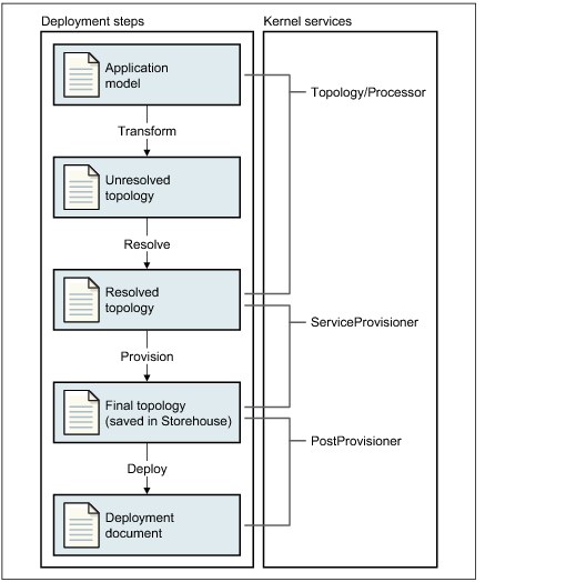
Figure 6-15 End-to-end deployment process
•Managing your deployed application
When your virtual application is deployed, it becomes a virtual application instance. You can use the PureApplication System console to see the virtual machine to which your application is deployed. Figure 6-16 shows the process of viewing the deployed virtual application instance.

Figure 6-16 Managing applications
6.5 Plug-in environment setup and creation of custom patterns
This section provides information about setting the plug-in environment and development of custom patterns, including the deployment of the pattern into PureApplication System.
The PDK contains a build environment, samples, and tools to create plug-in projects. The PDK can be downloaded from the welcome window of the PureApplication center.
To download the PDK, use the available download link for PDK in the PureApplication console (as shown in Figure 6-17) or from this website:

Figure 6-17 PDK download link
Complete the following steps to set up the plug-in development environment and create a sample plug-in:
1. Install and set up the environment.
After you download the PDK and extract the file, you can view the directory structure of the extracted content, as shown in Figure 6-18.

Figure 6-18 PDK extracted file
2. Set up the plug-in environment:
– You can use Eclipse as a development environment (Eclipse V3.6.2, 32-bit). The Java Platform, Enterprise Edition version is recommended, but is not required. You also can use Apache Ant, which is included the Eclipse download.
– Java Standard Edition 6, 32-bit, Apache Ant, 1.7 or later.
– Set ANTHOME so that Apache Ant can be located to run the build. You can use Apache Ant, which comes with Eclipse. Example location to find Ant binary:
C:UsersIBM_ADMINDesktopEclipsepluginsorg.apache.ant_1.8.3.v20120321-1730
– Run Apache Ant
Figure 6-19 shows the successful build and sample plug-in examples are created.
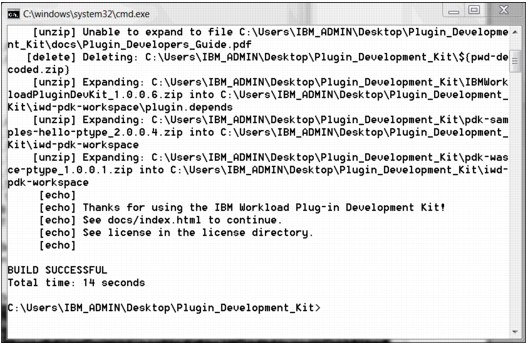
Figure 6-19 Apache Ant build
3. All of the packages, samples, and plug-ins are expanded within the workspace.
4. The workspace can be imported into Eclipse for plug-in and pattern creation.
5. You can use the sample imported examples as a starting point to create custom patterns. Complete the following steps to create your own plug-in project:
a. Copy sample hello pattern, patterntype.hello, and the plugin-depends projects from the iwd-pdk-workspace, as highlighted in the list of sample projects, which is shown in Figure 6-20.
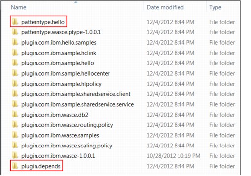
Figure 6-20 Sample example plug-in projects

Figure 6-21 Eclipse sample project structure
c. Right-click create.plugin.project.xml.

Figure 6-22 Create new plug-in project
e. Specify the plug-in project name and other configurations (such as -Dproject.name=plugin.myFirstPlugin, -Dplugin.name=plugin.myFirstPlugin, -Djava.classname=com.ibm.redbook.sample.myFirstPlugin), as shown in Figure 6-23.
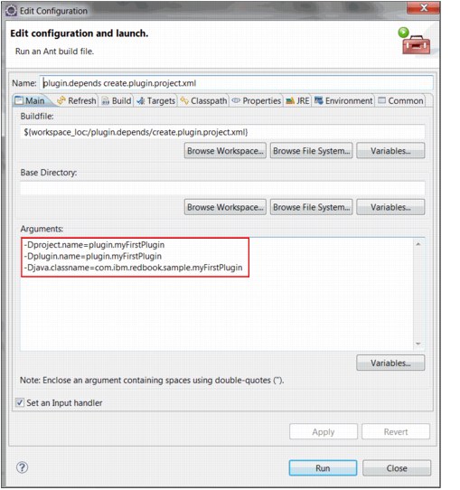
Figure 6-23 Plug-in name details
In Figure 6-24, the marked files are the files that must be edited or created for the sample plug-in.

Figure 6-24 Eclipse directory structure
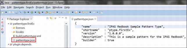
Figure 6-25 Sample patterntype.json
g. Edit the plug-in (config.json) file to have plug-in association with pattern type (ptype.firstEx), as shown in Figure 6-26.
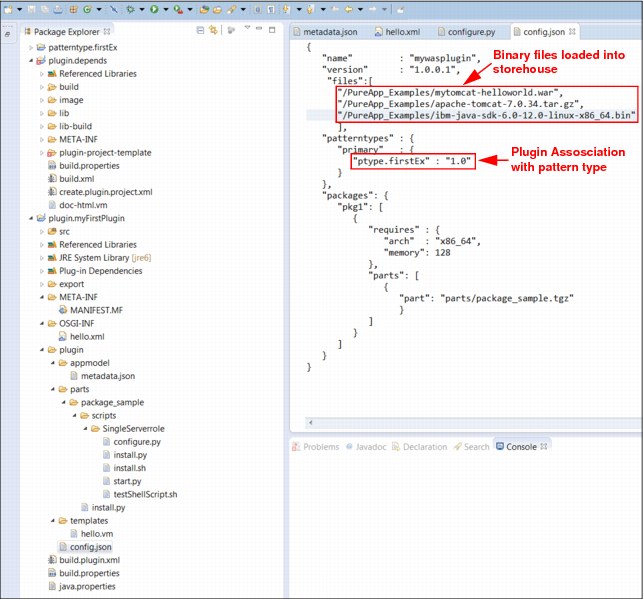
Figure 6-26 Plug-in Config.json
h. Edit the application model file (metadata.json) to include the component name (Single Server) and other attributes (attr1) that you want to make available to the user for customization, as shown in Figure 6-27.
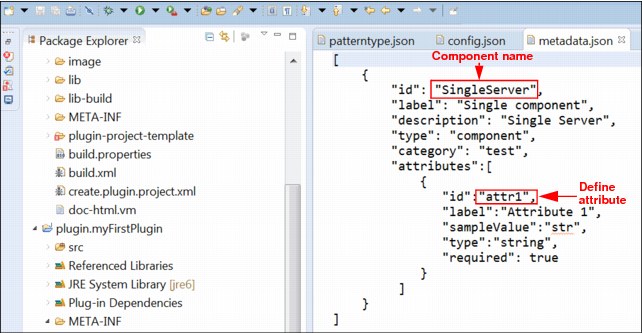
Figure 6-27 Application model metadata.json
i. Edit the transformer implementation class by using template topology. Associate the component (SingleServer) and the VM template (hello.vm), as shown in Figure 6-28. This process is how the transformation from application model to physical model is specified.
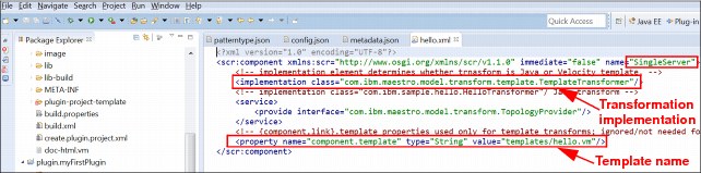
Figure 6-28 Topology hello.xml
j. Make sure that the service component includes the correct reference to the service registry in the “Manifest.MF” file, as shown in Figure 6-29.
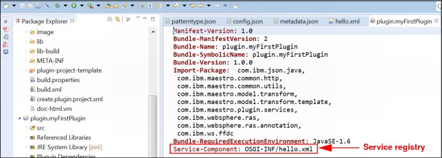
Figure 6-29 Sample Manifest file
k. Edit the template to specify the parts package for the plug-in, which you specified in config.json, as shown Figure 6-30.

Figure 6-30 Virtual template
l. Build the plug-in package:
i. Right-click build.xml in the plug-in-depends project folder.
ii. Select Run as.
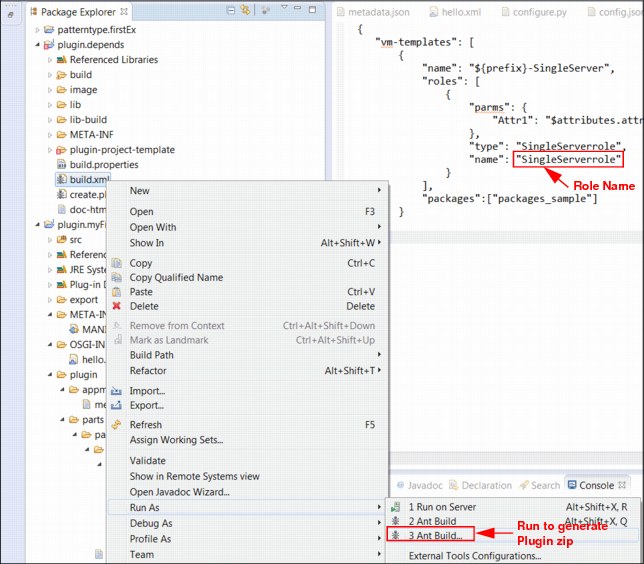
Figure 6-31 The build.xml in plugin.depends folder
m. Locate the plug-in build package in the image folder, as shown in Figure 6-32.

Figure 6-32 Plug-in exported .tgz structure in the image folder
Complete the following steps to build the pattern to include the plug-in package from the previous build:
1. Right-click build-patterntype.xml.
2. Select Ant build to generate the pattern package, as shown in Figure 6-33.

Figure 6-33 Pattern Build XML
The pattern package includes the plug-in package, as shown in Figure 6-34.
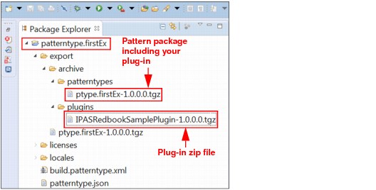
Figure 6-34 Pattern tgz file export location

Figure 6-35 Messages.json
The next step is to import your custom pattern type. After you build your pattern type, you import the .tgz file, which is located under the export directory.
Click PatternProjectName → Export → Archive to access your pattern project. For example, patterntype.firstEx → Export → Archive.
Your custom pattern type is now created. The next step is to install your new pattern. Complete the following steps to install the new pattern:
1. Log in to the IBM PureApplication System Workload Console and click Cloud → Pattern Type and then click + to install the new pattern, as shown in Figure 6-36.

Figure 6-36 Install the virtual pattern
2. Figure 6-37 shows how to upload the new pattern. Click Browse to locate the directory where you saved the custom pattern you created. For example: C:UsersIBM_ADMINDesktoppdkiwd-pdk-workspace_Redbookpatterntype.firstExexportptype.firstEx-1.0.0.0.tgz.
After you locate the file, you click OK to install the pattern.
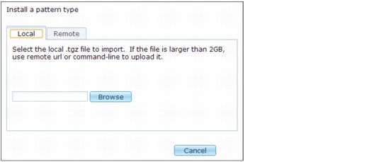
Figure 6-37 Upload .tgz file
3. After you import your pattern, the pattern is installed. You cannot create a virtual application unless you accept the license agreement, which is why you see a warning yellow sign, as shown in Example 6-38.
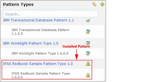
Figure 6-38 Installed pattern type after refresh
4. Click View to read and accept the license, which is required to enable the pattern, as shown in Figure 6-39.

Figure 6-39 Enable pattern
5. Now you must create the virtual application that is based on the pattern you installed. From the Workload Console, select Patterns → Virtual application to create a virtual application, as shown in Figure 6-40.
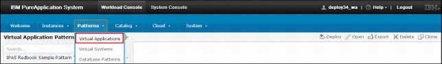
Figure 6-40 Create virtual application
6. Click Start to create a virtual application by using the pattern that you installed. The Virtual Application Builder interface of the PureApplication System opens in a separate window. In the left navigation panel, you find the example component that you created. Drag the Single Component into the editor, as shown in Figure 6-41. To the right side of the navigation panel, you enter the details about the name of virtual application.
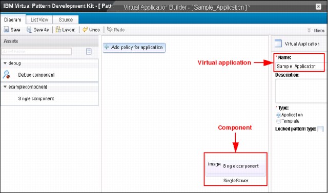
Figure 6-41 Virtual Application Builder for Single Component
7. Save the virtual application that you created by using the pattern that you imported, as shown in Figure 6-42. Click Save As and then click OK to save the application.
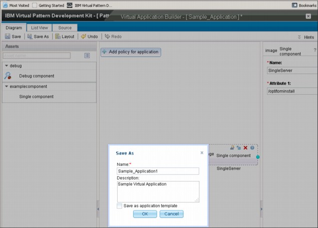
Figure 6-42 Save the virtual application
8. After the application is saved, deploy the virtual application. To deploy the application, from the workload console, select Patterns → Virtual applications. The window in Figure 6-43 on page 304 opens, which shows the name of the application. Select Deploy to deploy the application.

Figure 6-43 Deployment view of the sample virtual application
6.5.1 Troubleshooting and monitoring services
Plug-ins provide various operations that can be used to debug the deployed virtual applications. You can log in directly to the deployed virtual machine to run the scripts. The following websites provide more information about logging in to the deployed virtual machine:
To monitor virtual application patterns, plug-ins provide operations that enable troubleshooting. The following methods are available for monitoring, logging, and troubleshooting:
•Troubleshooting services for plug-ins
The troubleshooting service uses the deployment inlet operation capabilities with a recommended structure to provide consistency and reduce the work that is required by the plug-in to add troubleshooting operations. The troubleshooting python lifecycle script can start other scripts that the plug-in needs. It also can use helper methods that are provided by the troubleshooting service plug-in.
•Logging services for plug-ins
The logging service provides general service to collect multiple types (text, binary) information and transfers from the virtual machine to a store for review. This service presents a subset of the collected information in the Log Viewer page of the workload console and the Virtual Application Console deployment Log Viewer tab. Log Viewer can display only information for requested the virtual machine.
•High-level design of the log service
Plug-ins can use the generic logging service framework to specify what types of information must be collected and notify the logging implementation. You can use default log types to reduce the creation of numerous log types. Alternatively, you can create custom log files by specifying the type in the logtype-config.json file.
Example 6-3 shows a sample logtype configuration file.
Example 6-3 Configuration file logtype-config.json example
{"types":[
{
"name": "adaptorName2",
"description":"This is a new adaptor",
"format":"text"
"start": "\[\d{2}/\w{3}/\d{4}.*\d{2}:\d{2}:\d{2}:\d{3}.*\-\d{4}\].*Start:.*",
"end": "\[\d{2}/\w{3}/\d{4}.*\d{2}:\d{2}:\d{2}:\d{3}.*\-\d{4}\].*End:.*"
}
]}
•Plug-in interaction with the log service
Plug-ins must notify the logging service with a list of directories and files to collect for the log viewer and logging service implementations.
Plug-ins use the following methods inside the lifecycle scripts during the lifecycle execution:
– maestro.loggingUtil.monitor (jsonData)
– maestro.loggingUtil.unmonitor (jsonData)
– maestro.loggingUtil.registerPluginLogtype (file)
– maestro.loggingUtil.isImplementationRegistered (ImplName) [ImplName is the name of logging implementation class]
|
Important: First create a JSON file to list files and directories that must be monitored in the start.py script. Then, you can use any of the methods previously listed.
|
Example 6-4 shows example of calling logging service
Example 6-4 Calling for the logging service
listjson = '{ "role": "'+maestro.role['name']+'", "types": [ { "logtype": "SingleLine", "type": "file",
"name": "/opt/plugin/log/instance.log"}, {"logtype": "BinaryFile", "type": "dir", "name": "'/opt/plugin/log",
"pattern": "*.errlog"}, {"logtype": "File", "type": "dir", "name": "/opt/plugin/log"}] }'
maestro.loggingUtil.monitor(listjson)
•Create a log service implementation
A logging service supports the creation of custom implementations. These implementations act as the underlying process for a secure information transfer from the virtual machine and information storage for data review. Complete the following steps to implement a custom log service:
a. Create a pattern type plug-in that contains the logging service implementation that is registered with the logging service.
b. Register with logging service. Example 6-5 shows the method that is used to register and unregister logging implementation.
Example 6-5 Register and unregister by using a logging service
maestro.loggingUtil.registerImplementation(ImplName, ImplScript)
maestro.loggingUtil.unregisterImplementation(ImplName)
c. Implement methods such as monitor, unmonitor, and registerPluginLogtype in your custom code.
Each custom logging service must provide a python script with a method (monitor, unmonitor, registerPluginLogtype) implementations. These methods are started after the implementation is registered.
•Monitoring service for plug-ins
Plug-ins provide monitoring operations that collect and display deployment metrics for resource usage and performance at the virtual machine, middleware, and application levels. You can configure and register collectors for custom plug-in specific metrics at run time. Then, you can apply metadata to define the presentation of the monitoring metrics in the Virtual Application Console deployment panel.
6.5.2 Deploying and managing virtual applications
To build a virtual application, you can use a virtual application pattern or a virtual application template. You can use the virtual application template that is associated with a virtual application pattern to start building an application. After the virtual application is deployed, it becomes a virtual application instance.
You can deploy a virtual application by using a virtual application pattern or a virtual application template.
Virtual application pattern
For more information about deploying virtual application by using virtual application patterns, see 6.5, “Plug-in environment setup and creation of custom patterns” on page 286.
Virtual application template
Virtual application templates are designed for more flexibility and properties can be changed during deployment. Log in to the PureApplication System console and complete the following steps:
1. Click Catalog → Select virtual application template. Click the Deploy icon.
After the virtual application is deployed, you can see it under the virtual application instances pane. To view virtual instances, click Instances → Virtual applications, then perform any of the following tasks:
– To stop a virtual application instance: Select Virtual application → Stop.
– To start a virtual application instance: Select Virtual application → Start.
– To redeploy a virtual application: Select Virtual application → Deploy icon in virtual application builder pane.
– To remove a stopped application: Select Virtual application → Delete icon.
2. Secure the virtual application.
There are various security levels that are available to secure virtual application instances. Security can be set at the component level or at the instance level. The following security options are available:
– User permissions: You can protect the cloud environment by applying various security roles. For more information, see this website:
– Securing web applications with secure sockets layer (SSL): Virtual instances that are based on web application patterns can be secured by using SSL certificates. For more information, see this website:
– Configuring Secure Shell (SSH) key-based access: Configure SSH key-based access so that you can connect directly to virtual machines for troubleshooting and maintenance. For more information, see this website:
– Lightweight Third-Party Authentication (LTPA) keys for web applications: Manage LTPA keys for a virtual application instance that is based on the web application pattern. For more information, see this website:
..................Content has been hidden....................
You can't read the all page of ebook, please click here login for view all page.