

 High Availability and Disaster Recovery
This chapter describes high availability and disaster recovery aspects that are related to IBM PureApplication System. It includes different approaches and scenarios to demonstrate how high availability and disaster recovery can be achieved with IBM PureApplication System.
The following topics are covered in this chapter:
9.1 High Availability and Disaster Recovery overview
As IT becomes more pervasive in businesses and our daily lives, the impact of system downtime is increasingly significant. Outages affect productivity, create inconveniences, and result in loss of business. The globalization of the economy places a new demand for systems to be highly available and for the elimination of unplanned outages. If failures happen, systems should be able to recover rapidly and without losing data.
The causes of downtime might result from planned or unplanned events. The following types of downtime are possible:
•Planned downtime: Includes hardware upgrades, software updates, fix packs installations, and other maintenance work. Planned downtime often can account for a significant amount of the total downtime of a system.
•Unplanned downtime: A result of hardware failures, software bugs, infrastructure problems, human errors, site disasters, and natural calamities. Such unplanned outages are costly with significant impacts and customers want to reduce these outages.
The availability of a system is measured by the percentage in time that the application is available to a user. The application is considered highly available as it approaches the 99.999% of availability, commonly referred to as the five 9s of availability. The resulting availability is the combination of the availability of all components of a solution, such as the infrastructure layer, hardware, operating system, middleware, and applications.
High Availability (HA) is required when applications cannot undergo an unplanned outage for more than a few seconds or minutes at a time, but can tolerate short periods of not being available, or can be down for a few hours for scheduled maintenance. The system or component is equipped to handle faults in an unplanned outage gracefully to continue providing the intended functionality.
Continuous Availability (CA) refers to the ability of a system or component to be operational and accessible always, not allowing any kind of outage. Although HA compensates for unplanned outages, CA handles planned and unplanned outages. Therefore, CA extends HA with continuous operation.
Disaster Recovery (DR) is the ability to quickly reconstruct and start the applications in an alternative physical site if the primary data center has some catastrophic loss and cannot continue to run the application for an extended period. It is the process of bringing the servers and applications online in a priority order to support mission-critical applications at an alternative site. The alternative site need not to be the same physical size as the primary data center because its role is to quickly get the mission critical application up and running.
HA and DR in IBM PureApplication System is accomplished by using tools and procedures. IBM PureApplication System changes the automation aspects that make these procedures repeatable and easier for customers. In the following sections, we describe some fundamental concepts with regards to HA and DR.
9.1.1 Failover strategies
The key for implementing an HA system is to identify and eliminate single points of failure through redundancies, clustering, and other failover mechanisms. Redundancies mask system and component failures from users. The level of transparency for failure masking depends upon the following failover strategies:
•Cold standby: In this failover strategy, the primary component runs actively while the secondary or backup component stays dormant. When the primary component fails, the secondary component is activated to assume an active role. The interruption is visible to users.
•Warm standby: In this failover strategy, the primary component runs actively with the secondary or backup component that is running without active participation in workload management. When the primary component fails, the secondary component assumes an active role. Because the secondary component was running passively with partially synchronized data, the fail over is faster than a cold standby. There is still a minimal interruption to users.
•Hot standby: In this failover strategy, the primary and secondary components are actively running as a single, unified system. Active data replication happens between the primary and secondary components. When the primary component fails, the secondary component continues functioning without interruption to users.
9.1.2 Software clustering modes
Clustering is a technique that is used to create multiple copies of software components that are running actively and collaborating seamlessly to present a single, unified system. IBM WebSphere Application Server, which is included on PureApplication System, has inherent support for clustering. The following modes of clustering are available:
•Vertical clustering: In vertical clustering, multiple copies of the components are running actively on the same physical machine. The components are hot standby or in active replication. This configuration means that failure of one component presents no visible interruption to users. This clustering technique optimizes usage of the machine, although the single physical machine presents a single point of failure.
•Horizontal clustering: In horizontal clustering, components are created on multiple physical machines. This clustering mode is optimized for performance because only one instance of the software is present on each physical machine. It achieves similar software redundancy as in vertical clustering, with the other benefit of hardware redundancy.
•Vertical and horizontal clustering: Combines vertical and horizontal clustering techniques and maximizing the use of individual physical machines to achieve HA, performance throughput, and scalability.
These modes of clustering are shown in Figure 9-1.

Figure 9-1 Vertical and horizontal software clustering modes
9.1.3 HADR solution components
A complete high availability and disaster recovery solution incorporates data resiliency, infrastructure resiliency, and application state resiliency into one integrated environment that addresses one or all of the outage types. The behavior of a solution to a customer depends upon the inclusion and implementation of these three basic elements into the clustering configuration. These elements are described next.
Data resiliency
Applications require access to data or copies of the data to perform business-critical operations. Therefore, data resiliency is the base or foundational element for a high-availability and disaster recovery solution deployment. Data resiliency across multiple nodes in a cluster is the foundation for building an effective high-availability solution.
Local storage replication is the most commonly used technique for deploying cluster data resiliency. The following general topologies are used for storage-based resiliency:
•Active storage sharing (Active-Active): In this arrangement, the nodes of the cluster have simultaneous (concurrent) read/write access to the shared data. The cluster management technology performs locking operations to ensure that only one node can perform an update or write operation at a time. The benefit of this approach is that no switching operation is associated with storage resiliency because all the nodes simultaneously own the shared resource. If a node outage occurs, another node in the cluster resumes production through a reassignment process.
•Shared-disk configuration (Active-Passive): In this arrangement, only one node in the cluster performs read/write operations to the disks. Ownership of those resources can be passed to other nodes in the cluster as part of a failover (or rollover) operation. The operating system, application, and data are all switched between nodes. The recovery point is established by applying the journals that are in the shared disk resources. The recovery time is associated with the time it takes to apply the journal.
These topologies can be extended further for geographic dispersion by using host-based or storage server-based replication technology. Data in a storage pool can be replicated in a synchronous manner for zero loss implementations. It also can be replicated in an asynchronous manner for geographically dispersed sites where latency might affect operations.
Infrastructure resiliency
Infrastructure resiliency provides the overall environment that is required to resume full production at a standby node. This environment includes the entire list of resources that the application requires upon failover for the operations to resume automatically.
For an automated or semi-automated failover operation to work, all of the resources that the application requires to function on the primary node also must be present on the secondary node. These resources include the following items:
•Dependent hardware
•Middleware
•Network connectivity
•Configuration files
•Attached devices
•Security profiles
•Application-specific resources
•Application data
The cluster constantly monitors the resilient infrastructure resources for changes that indicate a failure, a pending failure, or a possible configuration change that might cause a cluster operation (such as a failover) or an operator to take corrective action. An aspect of monitoring is performing periodic verification checks. In these checks, specific or custom scans of the cluster resources are conducted to assess status against the intended configuration.
In addition to real-time monitoring, these operations are performed as an integrity check that supersedes the real-time monitoring function. A modern high-availability solution automatically identifies changes and addresses them through auto-corrective features or notifications methods. In addition to the monitoring and verification capabilities, cluster-wide management functions should be available to operators. To maintain or update the infrastructure, it is important to enable the operators to perform various operations on behalf of the application and operating system.
Application state resiliency
Application state resiliency is characterized by the application recovery point as described when the production environment resumes on a secondary node in the cluster. Ideally, the application resumes on an alternative node at the last state where the application was on the primary system when a failure occurred. Practically speaking, the characteristic of the application to resume varies by application design and customer requirements.
While application state resiliency depends on many characteristics of the environment, a high-availability solution should aid in monitoring the health of the application stack. This solution also should provide for corrective actions in the cluster to reduce failover times and to accelerate recovery times. For example, some middleware in a high-availability configuration might create a cache of application state information about another node in the cluster apart from the active node, thus enabling a quicker failover.
9.1.4 Disaster recovery models
When a disaster recovery model is chosen, organizations traditionally relied on the level of service that is required, as measured by the following recovery objectives:
•Recovery Time Objective (RTO): The amount of time between an outage and the restoration of operations.
•Recovery Point Objective (RPO): The point in time where data is restored and reflects the amount of data that is ultimately lost during the recovery process.
Traditionally, the following main disaster recovery models are available:
•Dedicated model
In a dedicated model, the infrastructure is dedicated to a single organization. This type of disaster recovery can offer a faster time to recovery compared to other traditional models because the IT infrastructure is mirrored at the disaster recovery site and is ready to be called upon in the event of a disaster. While this model can reduce RTO because the hardware and software are preconfigured, it does not eliminate all delays. This approach is also costly because the hardware sits idle when it is not used for disaster recovery. To mitigate the cost of ownership, some organizations use the backup infrastructure for development and testing, but that option introduces more risk into the equation.
•Shared model
In a shared disaster recovery model, the infrastructure is shared among multiple organizations. Shared disaster recovery is more cost effective because the off-site backup infrastructure is shared between multiple organizations. After a disaster is declared, the hardware, operating system, and application software at the disaster site must be configured from the ground up to match the IT site that declared a disaster. This process can take hours or even days.
With dedicated and shared disaster recovery models, organizations are forced to make trade-offs between cost and speed to recovery. As the pressure to achieve continuous availability and reduce costs continues to increase, organizations can no longer accept trade-offs. Disaster recovery originally was intended for critical batch and back-office processes. Now, many organizations are dependent on real-time applications and their online presence as the primary interface to their customers. Any downtime reflects directly on their brand image. An interruption of key applications such as e-commerce, online banking, and customer self service is viewed as unacceptable by customers.
9.2 Workload failover and recovery scenarios
This section describes the workload failure and recovery scenarios for the different deployment models in PureApplication System.
9.2.1 Virtual applications: WebSphere Application Server
The basic assumption for applications that are running on WebSphere Application Server in a virtual application deployment model is that the application is considered nonpersistent. This state means the application can run on any instance of WebSphere and there is no dependency that the state is locked in a specific instance. WebSphere Application Server instances can be started, stopped, created, and deleted as needed, sometimes without human intervention and with no impact on the running application.
For example, in a failure of a WebSphere instance, PureApplication System can provision another WebSphere instance in another virtual machine. If a WebSphere instance fails within a virtual machine and the VM is still running, PureApplication System monitors WebSphere process failures and restarts WebSphere once a day to prevent spinning of middleware. If scaling is enabled, PureApplication System starts another instance if the service level agreement (SLA) is not satisfied. There is no action that is needed by the deployer. At some point, the deployer can determine the cause of the failure by using the standard troubleshooting methods.
However, if the VM fails, PureApplication System detects the VM failure and respins another VM, assigning a new IP address. If scaling, routing, or caching policies are enabled, PureApplication System links the instance to the appropriate shared services. Again, there is no action that is required by the deployer. PureApplication System handles the recovery. The best practice is to have scaling enabled so that PureApplication System can manage the recovery to satisfy the SLAs that are required by the application.
9.2.2 Virtual systems: WebSphere Application Server without IMP
The failure and recovery of a WebSphere Application Server instance that is running in the virtual system deployment model without Intelligent Management Pack (IMP) is handled by the built-in capabilities of the middleware. PureApplication System does not monitor the WebSphere processes within the virtual machines in the virtual system deployment model. Normal troubleshooting and debug practices must be followed.
If a WebSphere Application Server node in Network Deployment topology fails, the Node Agent restarts the WebSphere node. This process is normal WebSphere function. If the Node Agent or the Deployment Manager fails, the deployer must follow normal WebSphere debug procedures to determine and fix the failure. The deployer can look at WebSphere log files, log in to the VM and restart WebSphere, debug from within the VM, or review the monitoring data for potential cause of failures.
If the VM that is running WebSphere fails, PureApplication System detects the VM failure, but there is no VM recovery. Deployers can try to restart the VM from the PureApplication System workload console and add more nodes by cloning the deployed instance while they debug the root cause of the failure. Table shows the different types of WebSphere failures for virtual system pattern scenario and the corresponding actions that are taken by PureApplication System and the deployer.
9.2.3 Virtual systems: WebSphere Application Server with IMP
The failure and recovery of a WebSphere Application Server instance that is running in the virtual system deployment model with IMP is handled by the built-in capabilities of the middleware. PureApplication System does not monitor the WebSphere processes within the virtual machines in the virtual system deployment model. Normal troubleshooting and debug practices must be followed.
The IMP provides dynamic clustering capability from the WebSphere Virtual Enterprise product. This capability allows WebSphere to provision more servers to satisfy SLAs, or when excess capacity is present, remove some servers and still maintain the SLAs when the load fails. For a dynamic cluster, if the SLA is not satisfied, IMP restarts WebSphere or creates more WebSphere cluster members, which are based on the settings. If a static cluster is used in WebSphere with IMP enabled, this scenario is the same as WebSphere with no IMP, as described in the previous section. For Deployment Manager failure, IMP can support backing up the Deployment Manager if the shared file system is configured, as explained in the WebSphere Virtual Enterprise information center, which can be found at this website:
If the VM that is running WebSphere fails, PureApplication System detects the VM failure but there is no VM recovery. Deployers can try to restart the VM from the PureApplication System workload console and add more nodes for static clusters by cloning the deployed instance. Adding nodes and restarting procedures can be done while they debug the root cause of the failure. Table shows the different types of WebSphere failures in the virtual system pattern scenario and the corresponding actions that are taken by PureApplication System and the deployer.
9.2.4 Virtual applications: DBaaS
The virtual machine for Database-as-a-Service (DBaaS) as part of a virtual application deployment is considered persistent. This configuration means that an individual database instance features non-replicated data and stores state. Therefore, in case of failure, PureApplication System cannot spin another database instance. Also, DBaaS as part of a virtual application is not scalable in the current release.
PureApplication System does not monitor DB2 failures. If there is a DB2 failure and the VM is still running, PureApplication System does not attempt to restart DB2. The deployer must review DB2 logs to identify the failure by accessing the VM by way of SSH and, if needed, restarting DB2.
If the VM that contains DB2 fails, PureApplication System detects the VM failure and restarts DB2 VM once at the same IP address because DB2 is considered persistent. If the VM does not come up after one retry, the deployer must create a DBaaS instance VM and then restore DB2 data from Tivoli Storage Manager backup. For use cases where data loss cannot be tolerated, periodic backups are essential. Table shows the different types of DB2 failures in the virtual application pattern scenario and the corresponding actions that are taken by PureApplication System and the deployer.
9.2.5 Virtual systems: DB2
The failover and recovery of DB2 that is running in virtual system deployment model is similar to traditional DB2 failure scenarios. It is handled like normal DB2 failures. PureApplication System does not take any special action and normal DB2 troubleshooting techniques should be applied.
If the DB2 failed but the VM is still running, PureApplication System does not monitor DB2 failures and therefore does not attempt to restart DB2. Clients must view the DB2 logs and log in to the DB2 VM to fix or restart DB2. Normal DB2 best practices and recovery processes apply to a DB2 that is running in PureApplication System. PureApplication System contains DB2 Enterprise and DB2 High Availability Disaster Recovery (HADR) images. For clients that need HADR capability, they can use the primary and secondary DB2 HADR virtual image parts.
If the VM containing DB2 instance failed, PureApplication System detects VM failure, but there is no restart of VM in virtual system. The client must review the logs, determine the failure, and restart the VM or create a VM. Standard DB2 backup and restore must be implemented. DB2 HADR can help here where the secondary DB2 can take over processing the requests. Table on page 385 shows the different types of DB2 failures in the virtual system pattern scenario and the corresponding actions that are taken by PureApplication System and the deployer.
9.2.6 Caching shared service
Caching shared service is provided through a pool of VMs for scale and redundancy. The number of VMs depends on the scaling policy of caching service, which includes auto-scaling that is based on the percentage of cache in use. Caching shared service uses WebSphere eXtreme Scale, which is robust. Internally, eXtreme Scale has its own processes that monitor the caching shared services.
If a caching shared service fails within a VM and the VM is still running, PureApplication System restarts the caching service. There is no action that is needed by the deployer. Caching VM is considered a persistent VM. Therefore, if a VM fails, PureApplication System detects the VM failure and restarts the caching service at the same IP address. There is no action that is needed by the deployer. If a primary or replica VM fails, it is restored and the cache is populated. PureApplication System handles the failures. Table shows the different types of caching shared service failures and the corresponding actions that are taken by PureApplication System and the deployer.
9.2.7 Proxy shared service
Proxy shared service supports scaling and the deployer can specify manual or auto scaling. These sets of proxy servers typically are front ended by an external load balancer. PureApplication System does not monitor proxy shared service failures. If the proxy shared service instance fails but the VM is still running, PureApplication System does not restart the proxy service.
However, if the client has multiple proxies that are defined through auto scaling, other proxy servers can be started that are based on the SLA. In the meantime, deployers can troubleshoot the problem and try to restart the VM. Because the proxy service is considered persistent, if the VM containing the proxy service fails, PureApplication System detects the VM failure and restarts the proxy service at the same IP address.
As a best practice, clients can use fixed IP address for the proxy services VM or have a separate smaller pool of IP groups for the proxy service. These sets of IP addresses then can be given to the front end load balancer to spray the requests. One way to achieve this configuration is to have a separate environment profile only for the proxy service and then use that for deployment of proxy shared services. Table shows the different types of proxy shared service failures and the corresponding actions that are taken by PureApplication System and the deployer.
9.2.8 Custom image
Custom images can be created by using the IBM Composition and Construction Tool or by using the PureApplication System extend and capture function. If the client uses one of the IBM supplied images as the base virtual image for creating a custom image, it includes the IBM Tivoli Monitoring OS agent by default to monitor the base OS.
All failover and recovery functions must be handled by the client in the image. If a custom image VM fails, PureApplication System does not monitor, respin, or restart the VM or any custom software within the VM. Clients are responsible for providing the failover and recovery mechanism for the software components that they add to the image.
9.3 Hardware high availability
Fault tolerance refers to the ability of a system to continue operation in case of failure of one or more of its components. This term often is referenced with high availability, particularly at the hardware level. Hardware redundancy (the addition of extra hardware for fault detection and toleration) is commonly employed in fault tolerant systems.
PureApplication System has built-in hardware redundancies for failover and recovery. So, if one of the following components fails, there is redundant hardware that assumes and prevents the system from interrupting the service:
•Management and virtualization nodes: Both of these nodes feature redundant backup servers that are continuously kept in sync with each other. PureApplication System has a floating IP address that is used to access the PureApplication System management functions. If one of the management nodes fails, the floating IP address is automatically assigned to the backup server and requires no change by the clients to access the management function.
•Network controllers: For the network controllers, there are redundant switches and cabling. Failure of one of the switches leads to reduced bandwidth; however, the rack continues to function.
•Storage and storage controllers: For storage, solid-state drives (SSDs) and hard disk drives (HDDs) are configured in RAID5, plus one spare. Therefore, RAID5 tolerates two concurrent drive failures without data loss. For the storage controllers, each controller has two canisters that can service all of the traffic to storage. If one of the canisters fails, the other handles the I/O.
•Compute nodes: If a compute node fails, PureApplication System attempts to move the virtual machine to another compute node that has free resources to accept the VM. The VM is moved within the compute nodes that belong to the same cloud group. This process is called rebalance or workload evacuation. If resources that are available on other nodes to handle the extra load is limited, the virtual machines are started based on their priorities. Appropriate messages and events are displayed for VMs that cannot be moved because of lack of space in other compute nodes.
9.4 High availability scenarios
IBM PureApplication System has built-in high availability features and is designed to not have a single point of hardware failure within the rack. However, to maximize these features, the software architectures and middleware topologies that are running on PureApplication System must be carefully planned and analyzed so that no aspect of the design is forgotten.
The following high availability features must be considered:
•Those features that are internal to the rack or intra-rack
•Those features that are across racks or inter-rack
In this section, we describe some of these scenarios for implementing high availability on PureApplication System.
9.4.1 Intra-rack high availability
In this scenario, a single PureApplication System rack is used to provide intra-rack high availability. A standard golden topology, including WebSphere and DB2 virtual system deployments that are running entirely inside the rack, is protected from failure by any one piece of hardware, such as a compute node, storage, or TOR switch.
As an example, when a compute node fails, the following actions occur as responses:
•The WebSphere middleware detects the failure of the Java VM and seamlessly routes the traffic to the other cluster members within the WebSphere cell.
•PureApplication System detects the compute node failure and moves the WebSphere VM to another compute node. After it is fixed, this node eventually is rejoined in the cluster by the plug-in and starts taking traffic again.
•For DB2 HADR deployments, if the primary database fails, the secondary DB2 is used to serve the requests.
The placement algorithms of PureApplication System are intelligent enough that, in most cases, two cluster members are never placed on a single compute node. This configuration is dependent on the configuration of the cloud group and the availability of compute resources within the cloud group. Figure 9-2 on page 388 shows a standard virtual system topology, including IBM HTTP Server (IHS), WebSphere Application Server, and DB2 HADR, which is enabled for intra-rack high availability.
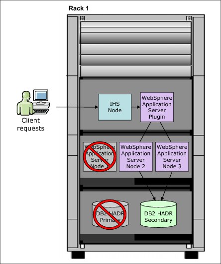
Figure 9-2 Standard virtual system topology that is enabled for intra-rack high availability
Intra-rack HA does not help if the entire rack fails because of some catastrophic conditions in the data center. That fact is where inter-rack high availability becomes important. You can again take full advantage of WebSphere, DB2, and other middleware facilities to provide this level of service.
9.4.2 Inter-rack high availability
This section describes some of the high-availability features across multiple racks. Standard middleware high-availability features are used to support high availability across racks. Many IBM middleware, such as WebSphere Application Server, DB2 Enterprise, and others include high-availability features that can be maximized in the same way as is traditionally done outside PureApplication System.
For example, to take advantage of the built-in HA features in WebSphere Application Server, you can provide one of the following failover topologies:
•Create WebSphere cluster nodes in the first rack and federate them to a Deployment manager (Dmgr) in the second rack, as shown in Figure 9-3.
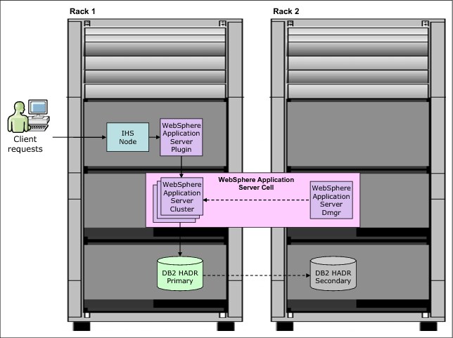
Figure 9-3 High availability topology with separate WebSphere Dmgr and cluster nodes
•Create two separate WebSphere cells (one per rack) and manage load distribution between the cells by using an on-demand router external to the two racks, as shown in Figure 9-4.
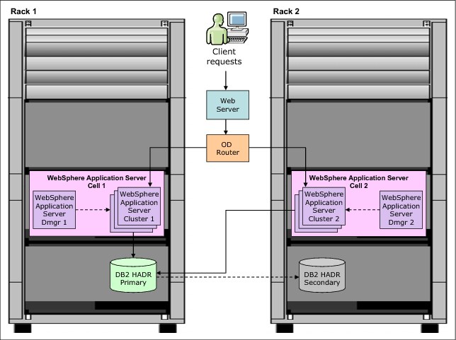
Figure 9-4 High availability topology with two separate WebSphere cells and external ODR
Both topologies must use standard DB2 HADR patterns to set up a primary database on a rack, with the backup database on the other (Active-Passive mode). For more information about these use cases, see 9.4.3, “Inter-rack high availability within the same data center” and Section 9.4.4, “Inter-rack high availability across distributed data centers” on page 392.
9.4.3 Inter-rack high availability within the same data center
In this high availability inter-rack scenario, which is referred to as the single cell model, a virtual system pattern that defines a WebSphere network deployment cell is created. It consists of one Deployment manager (Dmgr), one IBM HTTP Server (IHS) node, and WebSphere Application Server cluster nodes in the first rack, named Rack 1.
A virtual system pattern also is created on the second rack, named Rack 2. Rack 2 contains an IBM HTTP Server node and WebSphere Application Server cluster nodes that are federated to the Deployment manager that is running on Rack 1. The WebSphere Application Server HTTP plug-in for the IBM HTTP Server node is also present in the two racks. The DB2 HADR database is configured in an Active-Passive mode, with the primary (active) node on Rack 1 and the secondary (passive) node on Rack 2. This configuration defines the cell boundary as crossing both machines, as shown in Figure 9-5.
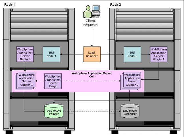
Figure 9-5 Single cell model across two racks in the same data center
It is necessary to create a virtual system pattern for the primary DB2 HADR node in Rack 1, and a second virtual system pattern for the secondary DB2 HADR node in Rack 2. For this configuration to work, it is necessary to configure an external load balancer to be aware of all of the IBM HTTP Server instances in the two racks. Deployers also must consider HTTP session management across the two racks. The simplest case in this approach is to enable database session persistence to the shared database.
In this configuration, IBM PureApplication System is now tolerant of a complete failure of either rack. The racks work in the following manner during a failover event:
•If Rack 1 fails, IBM HTTP Server instances and WebSphere Application Server cluster nodes on Rack 2 continue to take requests from the external load balancer. The DB2 HADR secondary instance takes over from the failed primary node. The only function that is lost is the ability to deploy changes to the cluster members on Rack 2 because the Deployment manager is no longer available.
•If Rack 2 fails, Rack 1 continues to function as normal and take requests from the external load balancer. Because the Deployment manager is in Rack 1, even the ability to deploy changes to the cluster members is kept.
9.4.4 Inter-rack high availability across distributed data centers
The case of two geographically separated PureApplication System racks is a bit more complicated in arrangement. The communication that is necessary between the Deployment manager and its cluster members (for management, code distribution, and so on) is inefficient over a wide area network. As a best practice, it is not recommended to federate cells across long distances. The recommendation is to create two cells, instead of joining all of the instances into a single cell, as shown in the previous scenario.
In this scenario, which is referred to as a dual-cell model, the deployer must create at least two individual cells by using a shared database, as shown in Figure 9-6 on page 393. As noted, the cell boundaries are entirely contained within each rack. In this way, the WebSphere cells are configured in an Active-Active mode, but the DB2 HADR database is configured in an Active-Passive mode (DB2 settings are same as arranged in the single cell model). The difference here is that the cells are independent from each other. Also, there is no inter-rack communication between the WebSphere Application Server cluster nodes, as shown in Figure 9-6 on page 393.

Figure 9-6 Dual cell model across two geographically distributed data centers
Complete the following steps to implement this approach:
1. Create the first cell with a virtual system in Rack 1 and export the virtual system pattern.
2. Import the virtual pattern into Rack 2 and create an instance of that pattern in Rack 2.
3. Use the deployer to create a DB2 HADR primary by using a virtual system pattern in Rack 1.
4. Create a DB2 HADR secondary with another virtual system pattern in Rack 2.
5. Set the external load balancer to feed traffic to the full set of IBM HTTP Server instances in both cells.
If either rack fails completely, the other rack continues to take traffic uninterrupted.
The use of HTTP session replication across two cells by using a shared database is possible, but it is rarely done. In most cases, session affinity is configured in the external load balancer. Requests for a session that was started in a particular cell always is outed to that cell. If you can tolerate lost session data in cases of a failover, you can set up a separate local database for session persistence.
9.5 Disaster recovery approaches
The following sections describe the different disaster recovery approaches that are available on PureApplication System for backing up and restoring virtual applications, virtual systems, and virtual appliance patterns.
9.5.1 Virtual application pattern backup and restore
Virtual application patterns can be exported and imported from the GUI console and the command-line interface (CLI), as shown in the following sections.
Back up by using the GUI console
Complete the following steps to back up a Virtual application pattern by using the GUI console:
1. Log in to the IBM PureApplication System GUI console.
2. Select Workload Console.
3. Select the virtual application pattern by clicking Patterns → Virtual Applications.
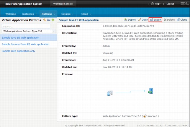
Figure 9-7 Exporting a Virtual Application Pattern by using the GUI console
5. Save the application .zip file to the local machine.
6. Extract the .zip file to get the application artifacts, such as EAR file and SQL schema.
Restore by using the GUI console
Complete the following steps to restore a virtual application pattern by using the GUI console:
1. Log in to IBM PureApplication System GUI Console.
2. Select Workload Console.
3. Select Patterns → Virtual Applications.

Figure 9-8 Importing a virtual application pattern by using the GUI console
5. The Import Application prompt window opens.
6. Enter the application name (optional).
7. Select the application .zip file to import. If the file size is larger than 2 GB, use the command-line tool to upload the file.
The .zip file is uploaded, validated, and if there is nothing wrong with the package, it is made available for use on the Virtual Application Patterns page.
Back up by using the CLI
Run the pure command (as shown in Example 9-1) to export a virtual application pattern. This process saves the application .zip file on the specified path. The .zip contains the application artifacts, such as the EAR file and database schemas.
Example 9-1 Command to export a virtual application pattern
Command:
C:pure.cliin>pure -a -h <host> -u <user> -p <password>
Welcome to the IBM PureApplication System CLI. Enter 'help' if you need help getting started.
>>> deployer.applications['<app_name>'].download('<local_file_path>')
Output: None
The following parameters are encountered:
•<host> is the IP address or host name of PureApplication System
•<user> is the user name for logging in to PureApplication System
•<password> is the user’s password
•<app_name> is the name of the virtual application pattern
•<local_file_path> is the local path to the .zip file that is downloaded
The name of all available applications can be found by running the following command on CLI:
deployer.applications
Restore by using the CLI
Run the pure command (as shown in Example 9-2) to import a virtual application pattern. This process creates an application pattern from the uploaded .zip file. The .zip file should contain all the application artifacts, such as the EAR file and database schemas.
Example 9-2 Command to import a virtual application pattern
Command:
C:pure.cliin>pure -a -h <host> -u <user> -p <password>
Welcome to the IBM PureApplication System CLI. Enter 'help' if you need help getting started.
>>> deployer.applications.create('<local_file_path>')
Output:
{
"access_rights": (nested object),
"acl": (nested object),
"app_id": "a-5a305cb1-03f2-4b31-bc69-0eaa096f8150",
"app_name": "Sample Java EE Web application Test Import",
"app_type": "application",
"artifacts": (nested object),
"content_md5": "57BD4C251935AAD00047AE6A343E0EEC",
"content_type": "application/json",
"create_time": "2012-12-21T01:03:16Z",
"creator": "user51",
"last_modified": "2012-12-21T01:03:18Z",
"last_modifier": "user51",
"patterntype": "webapp",
"version": "2.0"
}
The following parameters are encountered:
•<host> is the IP address or host name of PureApplication System
•<user> is the user name for logging in to PureApplication System
•<password> is the user’s password
•<local_file_path> is the local path to the .zip file that is uploaded
9.5.2 Virtual system pattern back up and restore
Virtual system patterns can be exported and imported only by using the CLI, as shown in the following sections.
Back up by using the CLI
A virtual system pattern can have virtual images, script packages, and add-ons. The exportPattern.py script, which is provided in the samples directory of CLI, can be used to download all the components from a virtual system pattern, as shown in Example 9-3.
Example 9-3 Command to export a virtual system pattern through CLI
Command:
pure -a -h <host> -u <user> -p <password> -f ..samplesexportPattern.py --pattern <vsp_name> --target <local_dir_path> --downloadAll
Example:
C:pure.cliin>pure -a -h 9.38.12.55 -u admin -p admin -f ..samplesexportPattern.py --pattern "vSysTest" --target ..ackup --downloadAll
Output:
Created a temporary directory "c:usersadminibm_ad~1adddatalocal empexportin7pev" for
Exporting pattern "vSysTest"...
Exporting script package "Install TradeDB App" to "script_packages/InstallTradeDBApp.zip...
Exporting script package "Install DB Drivers" to "script_packages/InstallDBDrivers.zip...
Exporting add-on "Default add user" to "add_ons/defaultadduser.zip...
Exporting virtual image "WebSphere Application Server 8.5.0.0" to "c:usersadminibm_ad~1adddatalocal empexportin7pevimages"...
Export virtual image "WebSphere Application Server 8.5.0.0" to "images/WebSphere Application Server 8.5.0.0.ova" successfully
Exporting virtual image "DB2 Enterprise 9.7.5.0" to "c:usersadminibm_ad~1adddatalocal empexportin7pevimages"...
Export virtual image "DB2 Enterprise 9.7.5.0" to "images/ DB2 Enterprise 9.7.5.0.ova" successfully
Export pattern "vSysTest" successfully.
The following parameters are encountered:
•<host> is the IP address or host name of PureApplication System
•<user> is the user name for logging in to PureApplication System
•<password> is the user’s password
•<vsp_name> is the name of the virtual system pattern
•<local_dir_path> is the path to the local directory where the files are downloaded
You also can export specific components by creating filters that use the JSON notation. For example, the filter exportAddOn.json, as shown in Example 9-4, export add-ons only from the virtual system pattern.
Example 9-4 Sample JSON filter for exporting add-ons from a virtual system pattern
{
"add_ons": [
{"name": "Default add user"},
]
}
The virtual system pattern add-ons can be downloaded by using a JSON filter, as shown in Example 9-5.
Example 9-5 Using a JSON filter for exporting add-ons from a virtual system pattern
Example:
C:pure.cliin>pure -a -h 9.38.12.55 -u admin -p admin -f ..samplesexportPattern.py --pattern "vSysTest" --target vSysTest.tgz --download exportAddOn.json
Output:
Created a temporary directory "c:usersadminibm_ad~1adddatalocal empexportin7pev" for
Exporting pattern "vSysTest"...
Exporting add-on "Default add user" to "add_ons/defaultadduser.zip...
Export pattern "vSysTest" successfully.
Restore by using the CLI
The importPatterns.py script, which is provided in the samples directory of CLI, can be used to restore all components from a virtual system pattern, as shown in Example 9-6.
Example 9-6 Command to import a virtual system pattern through CLI
Command:
pure -a -h <host> -u <user> -p <password> -f ..samplesimportPatterns.py --source <src_dir_path>
Example:
C:pure.cliin>pure -a -h 172.24.70.10 -u admin -p password -f ..samplesimportPatterns.py --source ..ackup
Output:
Importing pattern "VSPTestRestore01" ...
Import pattern "VSPTestRestore01" successfully.
The following parameters are encountered:
•<host> is the IP address or host name of PureApplication System
•<user> is the user name for logging in to PureApplication System
•<password> is the user’s password
•<src_dir_path> is the source directory from where the files are uploaded
9.5.3 Virtual appliance pattern backup and restore
Virtual appliance patterns can be exported and imported from the GUI console or the CLI. When you export a virtual appliance, an Open Virtualization Archive (OVA) file is saved to the local machine. This file can be imported later into another IBM PureApplication System.
Back up by using the GUI console
Complete the following steps to back up a virtual appliance pattern by using the GUI console:
1. Log in to IBM PureApplication System GUI Console.
2. Select Workload Console.
3. Select the virtual application pattern by clicking Cloud → Virtual Appliance.
4. Click the Export icon from the toolbar.
5. Save the OVA file to the local machine.
Backup by using the CLI
Example 9-7 Exporting a virtual appliance pattern through CLI
Command:
pure -a -h <host> -u <user> -p <password> -c "admin.virtualappliances['<vapp_name>'][0].export('<local_dir_path>')"
Example:
C:pure.cliin>pure -a -h 9.38.12.55 -u admin -p admin -c "admin.virtualappliances['testAppliance'][0].export('C:ackup')"
Output: None
The following parameters are encountered:
•<host> is the IP address or host name of PureApplication System
•<user> is the user name for logging in to PureApplication System
•<password> is the user’s password
•<vapp_name> is the name of the virtual appliance pattern
•<local_dir_path> is the path to the local directory where the files are downloaded
The name of all available appliances can be found by running the following command on CLI:
admin.virtualappliances
Restore by using the CLI
Example 9-8 Importing a virtual appliance pattern through CLI
Command:
pure -a -h <host> -u <user> -p <password> -c "admin.virtualappliances.create({'name':'<vapp_name>', 'importurl': '<import_url>'})"
Example:
C:pure.cliin>pure -a -h 9.38.12.55 -u admin -p admin -c "admin.virtualappliances.create({'name':'myName', 'importurl': 'file://C:/data/storage/templates/uploaded-template-134556812.ova'})"
Output:
{
"acl": (nested object),
"cloud": (nested object),
"created_time": "Jan 22, 2013 9:29:10 PM",
"description": None,
"id": "b732dc2f-6dbe-42f6-844f-dbbe22d9b189",
"importurl": "file:///data/storage/templates/uploaded-template-134556812.ova",
"name": "myName",
"state": "pending",
"updated_time": "Jan 22, 2013 9:29:10 PM",
"url": "/deployment/resources/images/b732dc2f-6dbe-42f6-844f-dbbe22d9b189",
"vmconfigurations": (nested object)
}
The following t parameters:
•<host> is the IP address or host name of PureApplication System
•<user> is the user name for logging in to PureApplication System
•<password> is the user’s password
•<vapp_name> is the name of the virtual appliance pattern
•<import_url> is the URL to the local file that is uploaded
This method returns a virtual appliance object for the new virtual appliance. Because of their size, importing virtual appliances can take several minutes. This method queues the operation and returns immediately. The returned object can be used to track the status of the import process.
9.5.4 Configurations backup
From IBM PureApplication System, it is possible to export other configurations such as DNS, cloud group, IP group, and user accounts. To export these configurations, run the saveAll.py command, as shown in Example 9-9.
Example 9-9 Command for exporting PureApplication System configurations
C:pure.cliin>pure -h 9.38.12.55 -u admin -p admin -a -f ..samplessaveAll.py
Generating report in 9.38.12.55 .txt...
Generating script in 9.38.12.55 .py...
Reading DNS data...
Reading NTP data...
Reading user data...
Reading user group data...
Reading IP group data...
Reading cloud group data...
Reading ipgroup data for Shared...
Reading compute nodes data for Shared...
Saved report to 172_18_24_12.txt.
Saved script to 172_18_24_12.py.
After the command is run, you have two files. One with the extension .txt and one with the extension .py. The .txt file contains information about appliance, DNS, NTP, users, user groups, IP groups, and cloud groups (IP groups and compute nodes). The .py file can be used to re-create the data that is found on the PureApplication System. The script creates users, IP groups, and cloud groups.
9.6 Current limitations
In this release of PureApplication System, there is no automatic process to set up another rack for disaster recovery. However, you can take the following steps to prevent system outages or minimize the service downtime:
•Create another rack that contains critical applications, either ready to run or already running in standby mode. This design allows a quick switch in a disaster.
•Set up an external sprayer to forward the requests. When the first rack is down, the sprayer can forward the requests to the backup system.
•At the core, continue to apply the normal disaster recovery mechanisms and standard procedures in use today.
•Back up critical databases, such as the stand-alone DBaaS or DBaas as part of Web Application patterns, by using backup solutions such as Tivoli Storage Manager. For DB2 VMs (as part of virtual system patterns), you can use the standard backup and restore mechanisms that are supported by DB2.
•Manage copies of image configurations, critical virtual applications, and virtual system patterns by exporting and importing to the secondary rack. This process can be done manually or automatically so that after the import, the scripts deploy the patterns and move them into a stable, configured state before they start taking traffic. You also can create the same users, groups, ACLs, and cloud configurations in the backup rack.
..................Content has been hidden....................
You can't read the all page of ebook, please click here login for view all page.