


Integrating PureData for Transaction
This chapter describes the integration of PureData for Transaction with PureApplication System. This integration helps you to use the databases from PureData for Transactions.
The following topics are covered in this chapter:
7.1 Advantages of integrating PureData for Transaction with PureApplication System
In this section, we describe the advantages of the use of PureData for Transaction system with PureApplication System. This integration provides you with rapid flexible data services solutions, data availability, on-demand resource allocation, and consolidation of database servers.
Integrating these systems includes the following advantages:
•Mission Critical Data
IBM PureApplication System and IBM PureData for Transaction integration enables your business to deploy optimized and continuously available mission-critical databases when you use these databases in IBM PureApplication System middleware applications.
•High availability of transactional data for IBM PureApplication Systems System
PureData for Transactions can provide built-in database clusters, which spread across multiple cluster nodes. DB2 pureScale® provides unlimited capacity, load balancing, and application transparency. This feature helps you keep your data available.
IBM PureApplication System, as the solution front end, and IBM PureData System, for the back end, work as a combined platform. IBM PureApplication System provides a high availability (HA) proxy server, application server, and caching server for applications that are deployed in this platform. IBM PureData System provides a highly available database server and storage resources for the platform.
•Speed
IBM PureApplication System is a highly efficient platform for applications deployment. When you use IBM PureApplication System and PureData system for transaction together, the user or customer can specify the requirements, such as when applications demand higher levels of scalability, availability, and performance. This solution allows the customer to easily and dynamically increase performance.
•On-demand resource allocation
IBM PureApplication System is a complete system platform of hardware and middleware. The user or customer drops applications into the system’s preconfigured middleware engine that includes IBM DB2 database and IBM WebSphere Application Server. You can dynamically adjust to demand spikes and reallocate the system resources automatically. Multiple applications and database patterns are provided (as part of the system) for optimally deploying and managing applications and resources in virtual and cloud environments.
•Consolidating the Database Server for Applications
These systems provide database server consolidation. You do not have to be concerned about managing individual database servers. A single interface makes it easier to manage the databases that are used by many applications.
•Scalability
This system integration also provides nondisruptive scalability. Administrators can add more nodes with no application changes required. The user or customer can start small and easily grow, with no need to over-purchase or over-provision.
7.2 Prerequisites for integrating the PureData for Transaction with PureApplication
In this section, we describe the prerequisites to integrate the PureData for Transaction system with the PureApplication System.
Integration requires the following prerequisites:
•Configure the connection between PureData System for Transaction and PureApplication System.
•Configure network communication between PureData System for Transaction and PureApplication System.
•Configure the trusted certificate between PureData System for Transaction and PureApplication System.
•Register the PureData System for Transaction with PureApplication System.
•Configure administrator access to the PureApplication System Workload Console.
•Configure existing user ID and password information for PureData System for Transaction. To use PureData System for Transaction, users must have the security administration role.
7.3 Registration of PureData for Transaction with PureApplication System
This section describes how to register the PureData System for Transaction with PureApplication System. Registration of PureData for Transaction with PureApplication System provides communication between PureData System for Transaction and PureApplication System.
Complete the following steps to register the PureData System for Transaction with PureApplication System:
1. Click the Workload Console tab at the top of the Welcome page to open the workload console on the PureApplication System.
2. Click System.
3. Click PureData System registration.
4. Complete the following fields, as shown in Figure 7-1:
a. Enter the IP address of PureData System for Transaction. This IP address is the same address that is used to access the PureData System for Transactions system console.
b. Enter the user name for this system; it must have the security administrator role.
c. Enter a password that is associated with the user name.
d. Click Register.
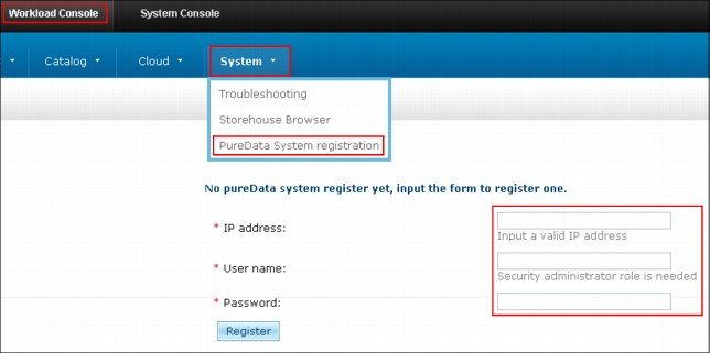
Figure 7-1 PureData system registration
|
Important: Only one PureData System for Transactions system can be registered with a PureApplication System at any time.
|
7.4 Deploying pureScale Database from PureData for Transaction
This section describes the steps to deploy the new pureScale database on PureApplication System.
You can create pureScale database patterns by using PureApplication System from PureData for Transaction. A new pureScale database is provisioned by specifying the provisioning options and deploying from PureData for Transaction.
Complete the following steps to provision a new pureScale database:
1. Click Workload Console.
2. From the Workload Console page expand the section Working with databases and click Deploy database, as shown in Figure 7-2.
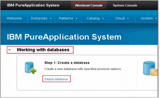
Figure 7-2 Deploy database
3. Configure and enter values into the following fields:
– Database Name: Enter the database name
The database name must be eight characters, begin with an alphabetical character, and contain an underscore (_). It does not have to include other special characters (such as ?, !, *, or @).
– Description of Database: A description of the database is helpful but not mandatory.
– Availability/Scalability: in this field, there are two options, standard and high. Select High, which is used for pureScale database from PureData for Transaction.
|
Important: You must have a DB2 pureScale instance that is deployed on the PureData System for Transactions before you create the database.
|
– Source field: You must select Apply a default database workload standard.
After you select Apply a default database workload standard, a default online transaction processing (OLTP) database is selected automatically, which is used for OLTP. The database is optimized for transactional applications.
– Default user: Enter the user name and in the Password field, enter the password for the default user.
– Database size: Enter the size of the database. In this example, 20-Gb size is used.
– Database compatibility mode: The default compatibility mode of database is DB2. You can choose the available database in list, for example DB2 (default) and Oracle.
– Database Version: You can select the version from the drop-down list. We used DB2 v10.1 for Linux. The version list is the database version and the supported operating system platform, for example, DB2 V10.1 for Linux.
– Database Level: You can select the database version and Fix Pack level with supported operating system from the drop-down list. We used DB2 V10.1FixPack Level 2 for Linux
– DB2 pureScale instance: Select the DB2 pureScale existing instance name, which is already created on PureData for Transaction system.
– Schema file: This field is optional. You can browse for your schema file if you choose to use one.
– Select Advanced Options to expand the field, and from the drop-down list you can select options for fields of Pagesize, Territory, Code set, and Collating sequence
– Pagesize: You can choose the page size for the database from the drop-down list. We used 4 as pagesize.
– Territory: Select the nation from the drop-down list, which can be used for database. We used US territory.
– Code Set: Select the standard character code set. We used UTF-8 code set.
– Collating Sequence: You can select the standard collating sequence of data source from drop-down list. We used SYSTEM.
4. Click OK after you enter the information in all of the required fields.
Figure 7-3 shows the fields and configuration page for the database.

Figure 7-3 Deploy database fields
After you click OK, the database deployment process is started. You can see the status of the deployed database request, as shown in Figure 7-4.

Figure 7-4 Deploy database status in Launching state
When the database instance status changes from Launching to Running, the following information about the database instance is shown:
•DB instance name
•DB instance IP address
•Port number
Click log to view the log.
Figure 7-5 shows the database instance display.
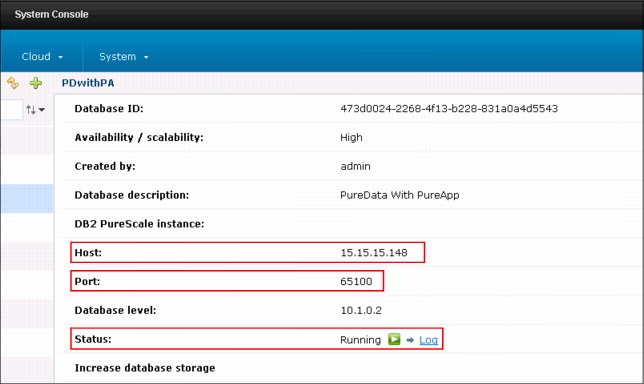
Figure 7-5 Database instance information
7.5 Deploying PureApplication System middleware
This section describes deploying an application from PureApplication System that fully employs the PureData for Transaction System. In this case, we are using existing data capabilities and we can constantly access the data. We are using the existing database instance, which was created in 7.4, “Deploying pureScale Database from PureData for Transaction” on page 313.
7.5.1 Creation of a virtual application pattern
To use the PureData for Transaction System, you must create a virtual application pattern to make the data services robust and more scalable. Complete the following steps to create the virtual application:
1. Click Workload Console.
2. On the Welcome page, click the Patterns drop-down list and select Virtual Applications.
3. Select the virtual application pattern type that you want to create, as shown in Figure 7-6. In this scenario, Web Application Pattern type 2.0 is selected and used.

Figure 7-6 Application pattern selection
5. When you click +, the Create Application window opens and you can create the customized application. Select Blank application and click Start Building, as shown in Figure 7-7.

Figure 7-7 Pane to start building your virtual application
6. When you click Start Building, the Virtual Application Builder opens in another browser window, is shown Figure 7-8 on page 320. In this scenario, the decision is made to create a virtual application for Enterprise Application for WebSphere Application Server. The scenario also associates an existing DB2 database from PureData for Transaction system to that virtual application. Complete the following steps to re-create this scenario:
a. Expand the Application components and drag the Enterprise Application component to the right side and onto the canvas, as shown in Figure 7-8 on page 320.
b. Expand the Database components and drag the Existing Database component for DB2 to the right side and onto the canvas, as shown in Figure 7-8 on page 320.

Figure 7-8 Virtual Application Builder window
c. Create the connection between the Enterprise Application component and the Existing Database component. The connection is made by dragging the blue dot (on the side of the component) from one component over to the other component, as shown in Figure 7-9.
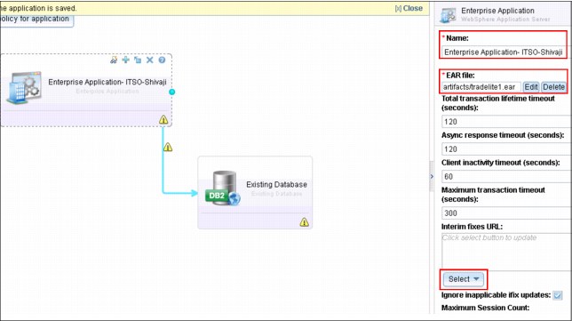
Figure 7-9 Application Components: Enterprise Application
d. Click Application components - Enterprise Application. After you click the component, the right side of the window gives you options for that component. You can then specify a name for the Enterprise Application, apply an EAR file, and select the interim fix pack from drop-down lists, as shown in Figure 7-9 on page 320.
e. Click the Database component - Existing database option. After you click this component, the right side of the window gives you options for that component. You can specify information in the following fields, as shown in Figure 7-10:
• Name: The name for the Existing database.
• Existing Database Name: The name for the database that you want to use from PureData for Transaction.
• The Server Hostname or IP Address, Server Port Number, User name, and Password fields are self-explanatory.

Figure 7-10 Database Components: Existing Database entry fields
f. Click the connection bar (which is made when you are connecting the components by using the blue dots). After you click the bar, the right side of the window gives you the options that are associated with the bar. You must specify the JNDI name of Data Source, as shown in Figure 7-11.

Figure 7-11 Field input for connection bar

Figure 7-12 Save the virtual application
8. Specify the name of the custom virtual application in the Save As window, as shown in Figure 7-13.
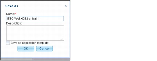
Figure 7-13 Saving your custom application
7.5.2 Deploying the virtual application
This section describes the process that is used to deploy the application that was created in section 7.5.1, “Creation of a virtual application pattern” on page 318. This scenario selects to deploy a virtual application for Web Application pattern type 2.0.
Complete the following steps to deploy the virtual application to deploy a new virtual application pattern:
1. Browse to Welcome page of the Workload Console panel.
2. Click Instances.
3. Select Virtual Applications to deploy a new virtual application pattern, as shown in Figure 7-14.
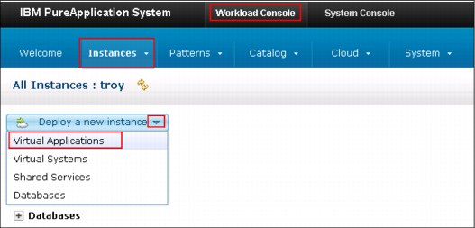
Figure 7-14 Workload Console panel
4. When you Select Virtual Applications in same pane, it opens Deploy Virtual Application pane. Select Pattern Type → Web Application pattern type 2.0, as shown in Figure 7-15.
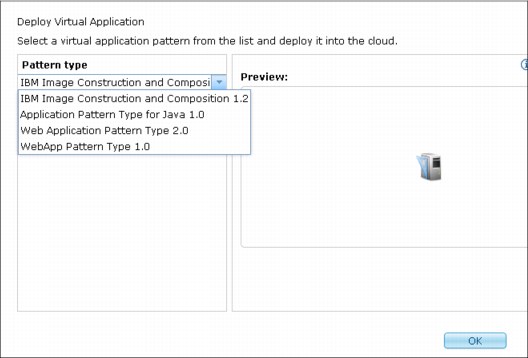
Figure 7-15 Deploy Virtual Application pane
5. Click Ok.
6. A pattern list is displayed, as shown in Figure 7-16. The pattern that was created in 7.5.1, “Creation of a virtual application pattern” on page 318 is available in the list.
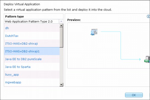
Figure 7-16 Pattern type list
7. Select the pattern that was created in the scenario or the pattern that you created when you complete the scenario, as shown in Figure 7-16.
8. Click OK.

Figure 7-17 Deploy Virtual Application pane
10. Specify the fields for Name and Filter by IP type (IPv4 or IPv6).
11. Select the profile type from the Filter by profile type drop-down list, as shown in Figure 7-18.
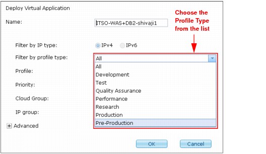
Figure 7-18 Filter by profile type list
12. Select the profile from the Profile drop-down list, as shown in Figure 7-19.
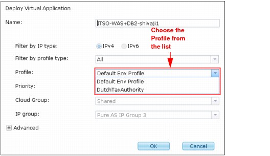
Figure 7-19 Profile list
13. Select the deployment priority from the Priority drop-down list, as shown in Figure 7-20.

Figure 7-20 Deployment priority list
14. Select the Cloud group from the drop-down list. In this scenario, there is only one cloud group (Shared), as shown in Figure 7-17 on page 326.
15. Select the IP group from drop-down list. In this scenario, there is only one IP group (Pure AS IP Group 3), as shown in Figure 7-17 on page 326.
16. Expand the Advanced option to generate or download the SSH key, as shown in Figure 7-17 on page 326.
The deployment status of the virtual application can be checked by using one of the following methods:
•In section 7.5.2, “Deploying the virtual application” on page 323 step 17, when you click OK, you see another pane in which you can click clicking here, as shown in Figure 7-21.
Figure 7-21 Check the status of deployment for the virtual application
•Click Workload Console. On the Welcome page of the Workload Console, click Welcome Page → Instances, then select the Virtual application to check its status, as shown in Figure 7-22.

Figure 7-22 Check the status of deployment for the virtual application
Click Workload Console. On the Welcome page of the Workload Console, click Welcome Page → Instances, then select the Virtual application. When the deployment of the virtual application is completed and successful, a green arrow status displays, as shown in Figure 7-23.
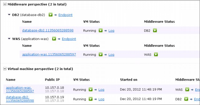
Figure 7-23 Successful deployment of a virtual application
..................Content has been hidden....................
You can't read the all page of ebook, please click here login for view all page.