


Integrating IBM PureApplication System into an existing data center
This chapter describes how to integrate the IBM PureApplication System into an existing environment. Sections include planning information and show the main connection options for the system. This chapter highlights the system-provided connection options and shows some best practices for consideration when you plan for these elements.
The following topics are covered in this chapter:
2.1 Prerequisites in the data center
PureApplication System is an integrated solution. Physically, it looks like another rack in the server room. This section describes the needs and preparation for the equipment in the new environment.
2.1.1 Physical requirements
Every component of the PureApplication System is in a standard 42-unit height enterprise rack. The necessary space for this equipment is the first physical requirement.
Electrical power consumption of the whole system is between 14.173 kVA and 32.770 kVA, depending of the configuration. Consider calculating and building for power consumption at maximum because this preparation supports future growth and development.
For more information about planning, see this website:
2.1.2 Software infrastructure requirements
A central time server is necessary for workloads to function seamlessly. Hypervisors and the VMs synchronize their time to this server. The basic way to synchronize the time between the servers is by using a network time protocol (NTP). This protocol provides a common interface to keep synchronized systems in the network. If the NTP server is inaccessible, all hypervisors use their own hardware clock and sometimes can get out of sync. Being out of sync leaves the system vulnerable and can create many problems during deployments.
Domain Name System (DNS) is a hierarchical distributed naming system for all resources that are connected to the network (intranet and internet). This domain name server also is an important part of the whole infrastructure. IBM PureApplication System uses DNS lookup services for communication. A DNS server is one of the required parameters for system initialization.
2.2 The Genesis process
To ensure the integrity of the IBM PureApplication System, IBM has a standardized process that runs when a customer orders a new system.
That process is the Genesis process. As a part of this process, some steps are run at the IBM location. The final step is run at client location with the audience of the customer who operates the system. The following steps are completed at the IBM location:
•Collect all the necessary information about each part.
•Check the assembly of the parts.
•Check the integrity of cabling.
•Run standardized tests on the new system.
•Update firmware and other software components.
•Verify, check, and complete the initial setup of the IBM PureApplication System for the client environment by using the worksheet that is completed by the customer.
The product is then shipped to the customer and at the client location. With the supervision of the client, an IBM Customer Engineer makes the final system configuration. Finalizing the new system settings includes steps such as setting up the management VLANs, switch port setup, and management of IP addresses. After this process is finished, a full reinitialization is done to change some system parameters.
During the initialization process, you must specify the following parameters:
•VLAN ranges for what you want to use: This configuration can be modified later from the management interface. For quicker integration and the first deployment test, initial parameters are required.
•Internal VLANs: These VLANs are reserved for internal communication and cannot conflict with any other VLANs. These values cannot be changed later.
•Virtual Link Aggregation Group Tier ID (VLAG Tier ID): This unique ID is used to connect other VLAG switches.
•Port setup: Configure rack switches.
•Link aggregations and configurations: Every switch port must be aggregated for best performance and stability. Configuration parameters help build these links.
•Management IP address and host name: This IP address or host name can be used for system management.
•DNS server address.
•NTP server address.
•IP group for the first test deployment.
•Administrative user and password.
2.3 Interfaces for using and administering IBM PureApplication System
A suitable interface must be chosen to best use the system. Usually, the best interface is a web-based GUI. However, when many similar commands are processed, Command-line interface (CLI) can be the best. IBM PureApplication System provides several interface options for system management.
2.3.1 Web GUI
Web GUI interfaces are the most mainstream way to administer the whole system. These interfaces do not need any extra installation on the client machine; only a web browser is required. Based on configured permissions, the interface shows all available options to use the system.
GUI structure
At the top of the initial IBM PureApplication system web page, you find the common options such as user name, help, logout, and the console selector links. There are two consoles available, the workload console and the system console. Both of these consoles include a welcome page that shows the main console with specific tasks.
Workload console
The workload console provides system management and administration for the cloud environment resources. Figure 2-1 shows the Welcome page of workload console.
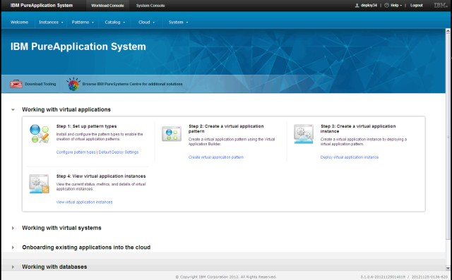
Figure 2-1 IBM PureApplication System: Workload console welcome page
System console
The system console covers system management and administration tasks for the hardware and software that are integrated in the system. Figure 2-2 shows the Welcome page of system console.
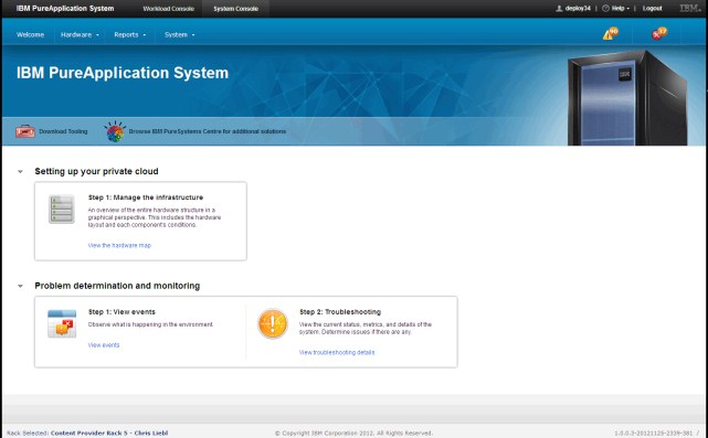
Figure 2-2 IBM PureApplication System and system console
2.3.2 Command-line interface
The IBM PureApplication System CLI provides a Jython-based scripting environment. The CLI is available for download from the GUI Welcome page. Figure 2-3 shows the download link on the welcome page.
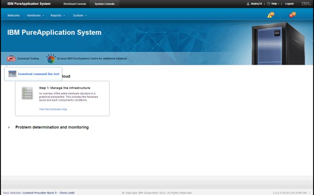
Figure 2-3 CLI download link on the welcome page
The CLI requires an installed Java V6+ runtime environment. Currently, this interface is supported on Linux and Windows OS.
The CLI contains all the same options that are available in the GUI and provides an interface to run complex automation scripts. The CLI package contains some other scripts for easy maintenance of the system.
For more information about CLI, see this website:
The following options and examples show how to connect to the system by using the CLI:
•Connect to PureApplication System interactive shell:
pure -h hostname -u username - p password
|
Tip: Specify only the host name or IP address; never use the full URL.
|
•Run a single command on system:
pure -h -hostname -u username -p password -c command
•Run a script file on system:
pure -h hostname -u username -p password -f file_name [args]
•CLI commands:
– Access the built-in content help:
help(..)
help(deployer)
help(admin)
– Query virtualsystems:
deployer.virtualsystems
Example 2-1, Example 2-2 on page 28, and Example 2-3 on page 28 give more specific information about the use of CLI commands.
Example 2-1 Example session to query virtual system from a command line
D:WorkPureSystempure.cliin>pure -h 172.18.64.32 -u demouser -p
demopassword -c deployer.virtualsystems
[
{
"acl": (nested object),
"created": 2012.11.29. 19:20:46,
"currentmessage": "RM07045",
"currentmessage_text": "The virtual system has been deployed",
"currentstatus": "RM01006",
"currentstatus_text": "Started",
"desiredstatus": "",
"desiredstatus_text": "",
"environmentprofile": (nested object),
"id": 240,
"maintenances": (nested object),
"name": "RHEL-GYG",
"owner": (nested object),
"pattern": (nested object),
"priority": 16,
"snapshots": (nested object),
"updated": 2012.11.29. 19:28:26,
"virtualmachines": (nested object)
},
{
"acl": (nested object),
"created": 2012.11.30. 14:25:15,
"currentmessage": "RM07045",
"currentmessage_text": "The virtual system has been deployed",
"currentstatus": "RM01006",
"currentstatus_text": "Started",
"desiredstatus": "",
"desiredstatus_text": "",
"environmentprofile": (nested object),
"id": 248,
"maintenances": (nested object),
"name": "VS RB-SA-W214-R01 - Test 1",
"owner": (nested object),
"pattern": (nested object),
"priority": 4,
"snapshots": (nested object),
"updated": 2012.11.30. 14:54:29,
"virtualmachines": (nested object)
}
]
D:WorkPureSystempure.cliin>
Example 2-2 Deploy virtual system from command line
dep=deployer.applications.get("a-90d408a5-735a-429d-b974-711abd99c276").deploy("CLI_Redbooks Test", {"environment_profile":deployer.environmentprofiles['envProfile34'], "cloud_group":deployer.environmentprofiles['envProfile34'][0].clouds.keys()[0], "ip_group":deployer.ipgroups['ipgroup34'][0], "ip_version":'IPv4'})
print dep.id, dep.status
Example 2-3 Deploy three virtual system from same script
vms=[]
for vmname in ["CLI1","CLI2","CLI3"] : vms.append(deployer.applications.get("a-90d408a5-735a-429d-b974-711abd99c276").deploy(vmname,{"environment_profile":deployer.environmentprofiles['envProfile34'], "cloud_group":deployer.environmentprofiles['envProfile34'][0].clouds.keys()[0],"ip_group":deployer.ipgroups['ipgroup34'][0] ,"ip_version":'IPv4'}))
for vm1 in vms: print vm1.id, vm1.status
2.3.3 REST API
Functional subsets are implemented in the representational state transfer (REST) application programming interface (API). The REST API is available by using the IP address or host name of the system. For more information about REST API configuration requirements and the full REST API reference, see this website:
Example 2-4 gives a detailed display of the use a REST session.
Example 2-4 Sample REST session to query virtual systems
GET:
https://172.18.64.32/resources/virtualSystems
RESPONSE:
[
{
"desiredstatus_text": null,
"currentstatus_text": "Started",
"name": "RHEL-GYG",
"desiredstatus": "",
"pattern": "/resources/patterns/2",
"id": 240,
"currentmessage_text": "The virtual system has been deployed",
"created": 1354213246476,
"currentstatus": "RM01006",
"creator": "deploy34",
"currentmessage": "RM07045",
"owner": "/resources/users/96",
"updated": 1354213706895
},
{
"desiredstatus_text": null,
"currentstatus_text": "Started",
"name": "VS RB-SA-W214-R01 - Test 1",
"desiredstatus": "",
"pattern": "/resources/patterns/208",
"id": 248,
"currentmessage_text": "The virtual system has been deployed",
"created": 1354281915208,
"currentstatus": "RM01006",
"creator": "deploy34",
"currentmessage": "RM07045",
"owner": "/resources/users/96",
"updated": 1354283669473
}
]
2.4 Security
An internal security system controls all access to PureApplication System resources that is based on user and group permissions. The IBM PureApplication System has an internal database to store user information and privileges, but it can use external LDAP server data for user authentication. The use of an LDAP server can help the data center administrator to manage the users lifecycle from the same system. The use of internal permission control is required because the LDAP server cannot serve permission information for the PureApplication System. The system also provides audit capabilities to monitor the system changes.
For security considerations, it is appropriate to separate the duties within the system. One of the most important directives is to isolate the assignments of auditing permissions to users who do not have other administrative capabilities.
2.4.1 User roles
The PureApplication System provides comprehensive options to adjust privileges. Management privileges are divided into five major areas. Each administrative role has a read-only or a full access option. The read-only option allows viewing of current settings only. The full access option has privileges to modify the settings. Another important option is the delegation role. With the delegation role, the user can delegate their own administrative access to another user.
For control of the administrative privileges, review the following available options:
•Workload resource administration read-only permission: Users with this role can view all workload-related configuration and status.
•Workload resource administrator full permission: Users with this role can manage all workload-related resources. This role also contains all read-only functions.
•Cloud group administration read-only permission: Users with this role can view all cloud resource configurations.
•Cloud group administration full permission: This permission also contains all cloud group read-only administrator rights and the management permission for these resources.
•Hardware administration read-only permission: Users with this permission can view all hardware-related resources.
•Hardware administration full permission: Users with this permission can manage the system hardware resources.
•Auditing read-only permission: Users with this permission can view auditing settings and audit date.
•Auditing full permission: Users with this permission can change auditing settings; for example, setting the external storage server connection data to automatically archive the audit log.
•Security administration view user/groups permission: Users with this permission have read-only access to view users and groups.
•Security administrator view all security resources permission: Users with this permission have read-only access to view all security resources.
•Security administrator manages security permission: Users with this permission can manage all security resources and can grant and revoke access rights.
•Allow delegation when full permission is selected: By using this option, the owner of the administration privilege can delegate their permission to another user.
The other important part of the permission controls is the workload management roles. The system provides the following options to control the access of resources:
•Deploy patterns in cloud: Every user has this permission and can deploy existing patterns to the system.
•Create new pattern: By using this permission, the user can create virtual systems and virtual application patterns.
•Create new environment profiles: By using this permission, users create environment profiles to group related cloud topology settings for easy deployment of virtual system patterns. The environment profile creator can edit and delete their own profiles.
•Create new catalog contents: Users can add objects to the PureApplication System catalog with this permission.
•IBM License Metric Tool: Users with this permission can start tool-related REST API calls to manage product licensing.
2.4.2 Group level permissions
The security system also provides group-level permission control options. By using group-level control, you can create groups of users with the same level of access to resources. With groups, the administration of roles can be more transparent.
2.4.3 Customer engineer access
Sometimes assistance is needed from IBM after a client moved through their troubleshooting procedures but did not resolve the failure. The system provides a special access flag that enables an IBM CE access to the system for 36 hours.
This option is available by browsing to System Console → System → Troubleshooting.
2.4.4 LDAP integration
Most large data centers have their own directory system, which helps centralized users and group management. PureApplication System also provides options to integrate with an existing LDAP directory. The LDAP authentication settings are available by clicking System Console → System → Security.
Figure 2-4 shows an example for LDAP settings. The LDAP parameters depend on the directory server. This sample is connected to an OpenLDAP server. After the LDAP setup, the system uses the chose server for LDAP user authentication. The content of the LDAP directory does not synchronize automatically with the system user or group directory.
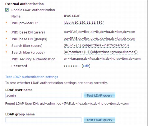
Figure 2-4 Sample external authentication settings
Automatic PureApplication System user creation that is based on LDAP
After LDAP authentication is enabled, the system can use LDAP passwords to authenticate the users. Before the user who was declared in LDAP can access the system resources, the security administrator must add the user to the PureApplication System user registry. This procedure can be a long process if many users need access to the system. In version 1.0 of PureApplication System, the GUI environment cannot automate the user creation process. If this ability is necessary, you must write a CLI script. Jython language provides elements to query LDAP user names and functions to create a user. In this case, the user creation method parameters must contain same user name as the LDAP user name.
2.5 License management
IBM PureApplication System contains some bundled software licenses and it provides some services to help the customer control the system's license usage. One of the usable license management tools is the IBM License Metric Tool. This component is available (at no cost) to monitor the IBM software license usage. Also, it can handle the virtualization environment special requirements.
2.5.1 Bundled software licenses
The following products are delivered with the system as integrated patterns. PureApplication System includes entitlement to run the following products up to the total capacity of that configuration:
•IBM WebSphere Application Server Hypervisor Edition, V7.0 and V8.0
•IBM DB2 Enterprise Server Edition, V9.7 FP5 and V10.1
•IBM Web Application Pattern, V1.0 and V2.0
•IBM Transactional Database Pattern V1.1
•IBM Data Mart Pattern V1.1
•IBM Application Pattern for Java V1.0
•IBM OS image for Red Hat Linux Systems V2.0
2.5.2 IBM License Metric Tool
The IBM License Metric Tool is used for license tracking purposes across a range of IBM software products. The IBM License Metric Tool is packaged independently and is available as a software download from IBM that is separate from the PureApplication System. The PureApplication System supports communication with the IBM License Metric Tool to produce enterprise-wide license usage reports. To use this feature, you must point to an IBM LMT server in the PureApplication System configuration. The virtual images that the PureApplication System deploys include the IBM License Metric Tool agent. This agent runs on the virtual machines (VMs) that are deployed in the cloud and collects data about the software that is running there and the licenses that are used. The agent then sends this information to the IBM License Metric Tool server.
2.5.3 License information
PureApplication System provides information about the used licenses and features capabilities to configure the license usage limits. The system also provides the option to download filtered license statistic information. The license information about the system is available by browsing to System console → System → Product licenses. Figure 2-5 shows an example license statistic.
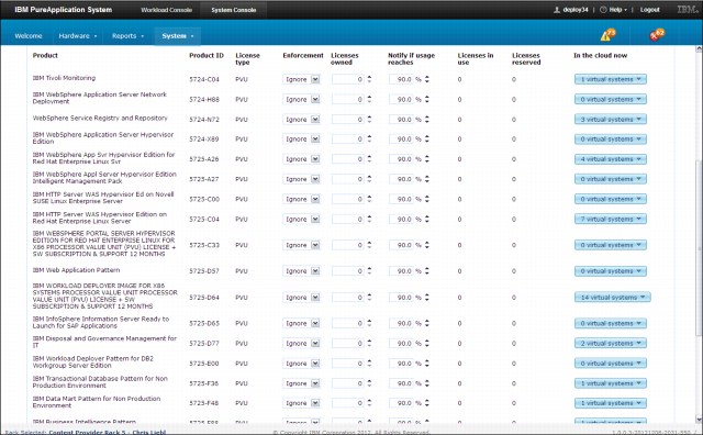
Figure 2-5 Sample license usage statistic and settings
2.6 Networking
The network is the only connection between the system and the outside world. If something is wrong in the network configuration, the whole system might be inaccessible. Therefore, care must be taken when the network environment is planned.
2.6.1 Networking hardware in IBM PureApplication System
From the hardware side, every PureApplication System contains three Flex System Enterprise chassis and two top-of-rack switches with 64x10 Gb ports. Every chassis contains two10 Gb Ethernet switches. The top-of-rack switches provide the connection to the outside network. Each compute node has two Ethernet controllers, each with 4x10 Gb Ethernet ports.
|
SAN network: The system also contains a storage area network (SAN), which is used internally and does not connect to any external SANs. In the current version, the SAN cannot be extended.
|
Details of all hardware components, including the network devices that are within the system, are available by browsing to System console → Hardware → Infrastructure map. The hardware menu also contains more options to filter the devices according to function. The details of the network part of the system are available by browsing to System console → Hardware → Network devices.
Figure 2-6 shows an example list from the network devices.
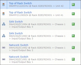
Figure 2-6 Example list from network devices
Figure 2-7 shows an example of top-of-rack switch details.
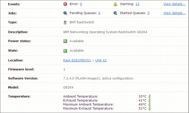
Figure 2-7 Example of top of rack switch details
Figure 2-8 shows top-of-rack for the customer port details.
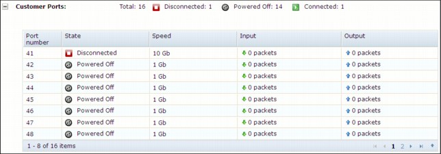
Figure 2-8 Example of top of rack switch customer ports details
2.6.2 Main networks
For secure and reliable operation, it is necessary to separate the network traffic that is based on functionality. IBM PureApplication System uses four main network segments. Each segment has its own functionality. The system uses IPV6 for internal communication and IPV4 or IPV6 for the external network.
The following list describes the four main network segments:
•External access network
The external network connects to the customer network. It can be segmented into multiple VLAN ranges. It is configurable to 1/10 Gb, depending on the customer network needs. Workloads use the external network for all in and out traffic.
•Console network
The system uses this internal network to communicate with management tools, such as the system console.
•Mobility network
When workload relocation is required, the system uses this internal network to move the virtual machines between the nodes.
•Management network
The management network is an internal network that is used for communication between the management and compute nodes.
2.6.3 Port setup
Top-of-rack switches provide 2x16 ports to connect the system to the external network. Ports 41-56 in each switch are available for connectivity to external networks. At least one cable is required in each switch for proper operation. Total bandwidth between the PureApplication System and the external network depends on the used ports and the port configuration. The minimum bandwidth, in and out from the rack, is 2 Gbps and the maximum is 320 Gbps. The configuration of each port can be changed individually. A best practice is to configure the two switches identically. This configuration ensures optimum traffic flow, easier debugging, and a resilient network configuration.
Figure 2-9 shows an example port setup. The customer network configuration is available by browsing to System Console → System → Customer Network Configuration.
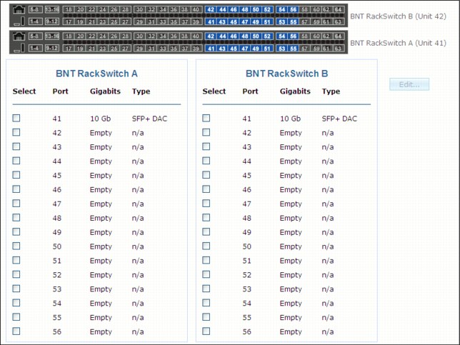
Figure 2-9 Example port configuration
Figure 2-10 shows ports that are selected at the same time to change both of their settings. Multiple selections are more efficient for port configuration. By default, when one port is selected on switch A, the same pair on switch B is selected. Ports can be cleared manually.
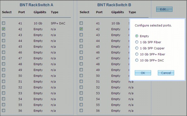
Figure 2-10 Port configuration options
An important port setting is the management port setting, as shown in Figure 2-11. The last port in every top-of-rack switch is reserved for external management access. This port provides access to the management interface of the PureApplication System.
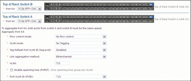
Figure 2-11 Management port settings
2.6.4 Link aggregation
After all usable external switch ports are configured, the next task is to combine these ports with an aggregated link. Link aggregation is a switch feature that enables the combination of multiple physical ports into a logical link. This configuration provides higher bandwidth and more resilient redundancy. All aggregated links must contain at least one port from each switch.
|
Important: Aggregated ports must be of the same speed.
|
2.6.5 VLANS
The basic way to sort the network traffic between the separated virtual applications is by using the virtual local area network (VLAN). VLANs can provide near physical levels of separation and protect the traffic of each virtual application. The entire system features three dedicated VLANs, which must be reserved and cannot be mixed with other VLANs.
|
Important: Internal network VLAN IDs, which are configured during the genesis process, cannot be changed from the administrative console.
|
The system provides a management interface to configure the VLAN ranges. Figure 2-12 shows the VLAN configuration part of the customer network configuration form.
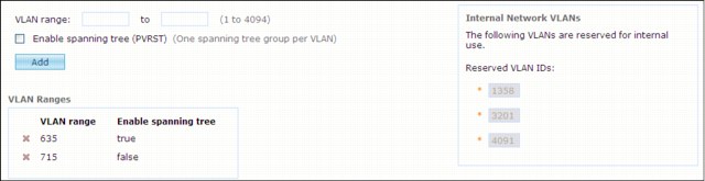
Figure 2-12 VLAN configuration form
When you consider the relation between ports, aggregations, VLANs, and IP groups, remember the following points:
•Every aggregation contains at least two physical ports.
•Every VLAN is mapped to an aggregation.
•Every IP group is mapped to a VLAN.
2.7 Auditing
PureApplication System provides a continuous logging function that records all security and administrative events. This log data can be the source of the audit log. A user who has auditing permission can read this information from the system. Audit records cannot be deleted by a user. This record stays in the system’s internal database until storage has more space. If the storage full, the system automatically deletes the oldest records. To prevent the loss of audit log records, the system is configurable to back up the audit log records to an external storage. In this case, the old records are stored on the external storage before the system deletes them from the internal database.
2.7.1 Auditor roles
The system provides the following permission options to grant audit rights to a user:
•Read only permission: With read only permission, the user can view all audit data from system.
•Full access permission: With full access permission, the user can change the audit settings to use external storage for audit data archiving.
|
Important: Audit data modification or deletion is not possible in the system. The system deletes the oldest audit data when the audit storage is full. If external storage is configured, this data is archived into external storage.
|
2.7.2 External storage server for audit logs
The internal storage for the audit records is limited. Depending on the number of the events, it can be full. In this case, the system protects integrity by deleting the oldest record to make space for the new records. Based on the number of records and storage size, it might not be necessary to back up the records because deletion might not occur for some time. If the company decides it wants a longer time period to store and analyze these records, the records must be saved on external storage. The system provides options for this requirement. Only users with full auditing permissions can access this configuration option. Figure 2-13 shows the external storage options for audit logs.
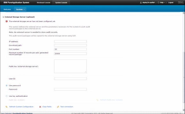
Figure 2-13 External storage server options for audit logs
2.7.3 Handling audit data
Users with at least audit reader permission can view all audit data on the system. This function is available by browsing to System Console → System → Auditing. Figure 2-14 shows an example of the audit data.
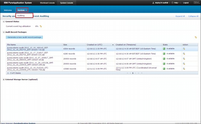
Figure 2-14 Security and Administrative Event auditing
The system provides a function to generate a new audit record package. This function enables filtering of the requested data between start and end time. Figure 2-15 shows the audit data generation panel.
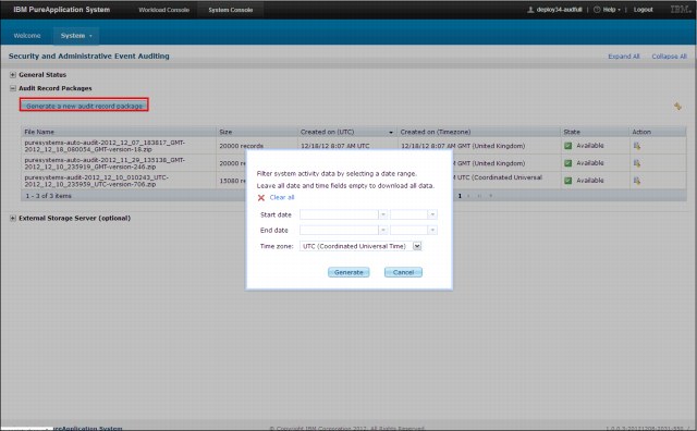
Figure 2-15 Generating an audit data package
The generated data can be download from the Audit record packages section. Figure 2-16 shows example content of the generated file.
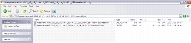
Figure 2-16 Generate audit log file content
The downloaded audit package is a .zip file that contains two files. The checksum file contains information to check the audit file integrity. The audit records are in a text file with a .csv extension. This file contains a header row line and the audit records. Every line contains comma-separated values. All audit records contain the following columns:
•Timestamp
•ComponentType
•ActionId
•ResourceID
•UserID
•IP
•AdditionalData
2.8 Monitoring
PureApplication System provides comprehensive features to monitor system activities. Integrated components provide a single place to track all events and check the status of the system. The system provides some standard interfaces that help to integrate your system into an existing monitoring infrastructure.
2.8.1 Integrated solutions
The monitoring infrastructure of the PureApplication System is designed to facilitate locating the necessary information for users and operators. From the security side, every user has their role in the system. Deployers can see only their middleware or database metric. Monitor operators can access all user deployments and the monitor administrator can access hardware metrics.
The dashboard provides drill-down navigation on the elements of workloads. This ability helps to focus attention on required elements. If more details are required, the user can dig deeper. This interface also provides a log viewer feature to help experts solve workload issues.
Figure 2-17, Figure 2-18 on page 46, and Figure 2-19 on page 47 show aspects of drill-down navigation between the components of a virtual application.
Figure 2-17 shows basic monitoring information. To open the details about this page, click the first VM.
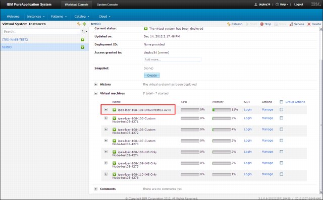
Figure 2-17 Deployed virtual system basic monitoring information
Figure 2-18 shows more information and management options. Click Manage action, then click More to drill down for more information.
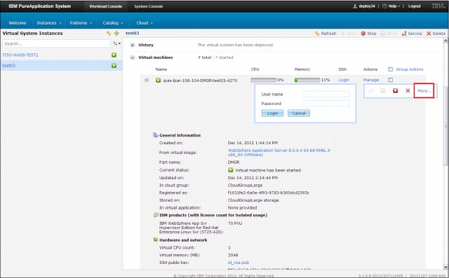
Figure 2-18 More information and management options
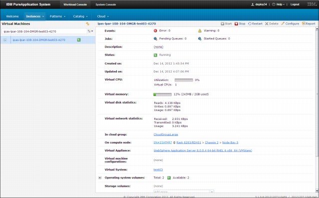
Figure 2-19 Next level and virtual machine monitoring information
The system provides more detailed monitoring information with the PureApplication System Monitoring portal. To access the portal client, complete the following steps:
1. Choose a virtual application instance.
2. Click Manage.
3. On the Monitoring tab, click Advanced monitoring, which starts the PureApplication System Monitoring Portal Client.
2.8.2 PureApplication System Monitoring Portal
The PureApplication System Monitoring Portal offers a dashboard view of your critical enterprise IT resources.
Requirements
The portal user interface is a Java-based GUI, which requires IBM Java 5 or later to be installed.
Overview
The following list describes the important elements for the monitoring portal:
•PureApplication System Monitoring Server uses installed agents to collect monitoring data from the monitored systems.
•PureApplication System Monitoring Portal Server connects to the PureApplication System Monitoring Server to retrieve collected events and performance data. The server also provides a collection of software services for the PureApplication System Monitoring Portal client.
•The PureApplication System Monitoring Portal client provides a Java based dashboard for analysis of the monitoring data.
Figure 2-20 shows sample content from the PureApplication System Monitoring Portal client. The navigator view provides a hierarchical view of your enterprise and helps to browse specific resources.
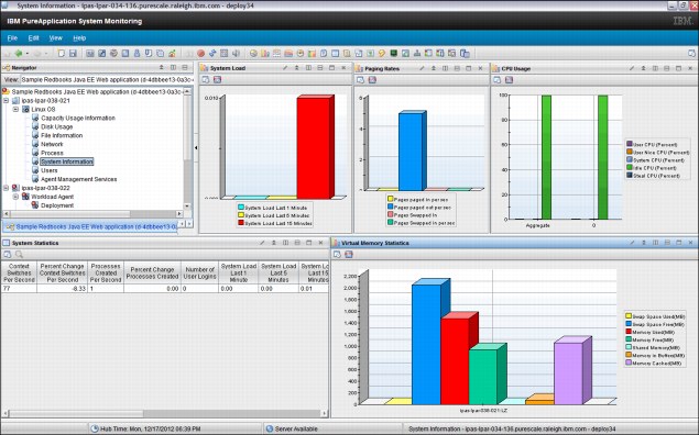
Figure 2-20 PureApplication System Monitoring Portal client
2.8.3 Monitoring layers
The entire monitoring infrastructure in PureApplication System can be divided into layers from the hardware level to the system level through the middleware. The following list describes the layers in greater detail:
•Hardware monitoring
At the hardware level, the system provides an infrastructure map that contains all of the important monitoring information in one place. It shows an overview of the compute nodes, storage system, network switch, and LED status.
•Middleware monitoring
You can monitor the workloads and instances with PureApplication System. For the monitoring facilities to be displayed in the workload console, you must deploy monitoring shared services. A subset of middleware monitoring functions is required to use the installed agents. Information for monitoring also is provided by the integrated parts of the system.
•System monitoring
The system monitoring service provides the monitoring infrastructure that collects performance and availability information. Use the system monitoring service to troubleshoot your system and make business decisions about your hardware and service usage.
Layered monitoring is critical to a healthy system and allows IT teams to be proactive in preventive maintenance. Figure 2-21 shows the graphical infrastructure map of the rack that is used for monitoring.
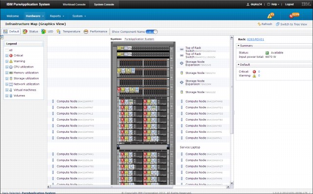
Figure 2-21 Hardware infrastructure map
2.8.4 External monitoring
Many external enterprise monitoring solutions can be used with PureApplication Server. For example, an IBM Tivoli/Omnibus external server can be configured as a trap destination for SNMP events from PureApplication System. These events include selected hardware and software events. A single PureApplication Server MIB is provided for external enterprise monitoring solutions and a set of OMNIbus rules are provided for IBM Tivoli Netcool/OMNIbus. The system provides a download link for MIB and OMNIbus rules from the GUI. Files are available by browsing to System Console → System → Event forwarding. Figure 2-22 shows the download links for the necessary rules.
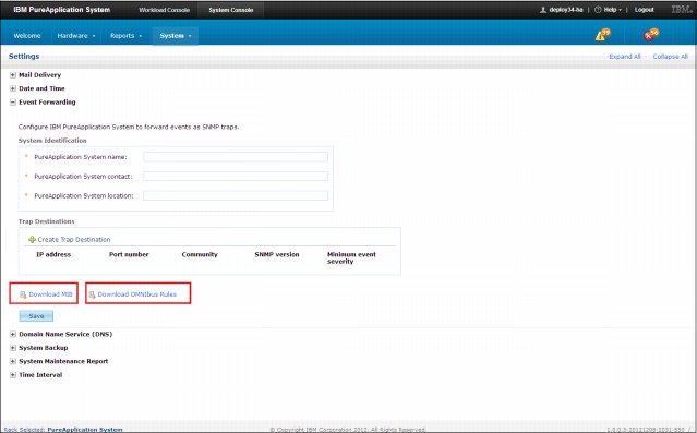
Figure 2-22 Download links for MIB and OMNIbus rules from the GUI
2.9 Integration with external backup systems
Tivoli Storage Manager backup capabilities are integrated into the PureApplication System user interface. You can create an online backup of the database image, schedule an automatic backup, and list the existing database image backups.
This functionality is not limited to databases that are defined in a database pattern. It also applies to databases defined in virtual applications. Backup functionality requires that the Tivoli Storage Manager system plug-in is configured. Tivoli Storage Manager is not included in PureApplication System.
If Tivoli Storage Manager is configured, the default schedule for backups is daily. If Tivoli Storage Manager is not configured, scheduled backups are set to OFF until you select a frequency. After the backups are scheduled, they run automatically at 23:00.
The restore of any of these backups must be done by using Tivoli Storage Manager. You also can create a manual backup. Manual backups are recommended if you plan to use the backup as a clone in a new database instance.
2.9.1 Tivoli Storage Manager System plug-in configuration
The Tivoli Storage Manager plug-in is available by clicking Workload Console → Cloud → System plug-ins, then selecting the plug-in from the IBM Database Pattern category. Figure 2-23 shows the configuration options for Tivoli Storage Manager integration. This form contains the connection details to access a Tivoli Storage Manager server.
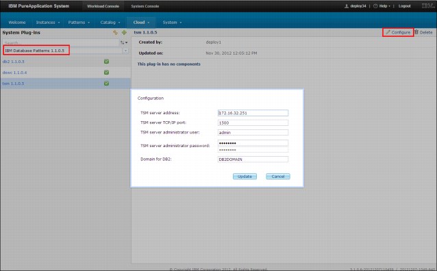
Figure 2-23 Tivoli Storage Manager plug-in configuration
2.9.2 Configuring a scheduled Tivoli Storage Manager database backup
Every instance of a database is configurable to use Tivoli Storage Manager for a scheduled backup. By default, the database instances are scheduled for a daily backup. Figure 2-24 shows the settings section and the options for automatic backup.
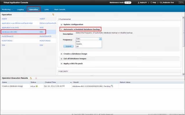
Figure 2-24 Virtual application database backup settings
This option also is available for stand-alone database instances. Figure 2-25 shows the configuration section on database console.
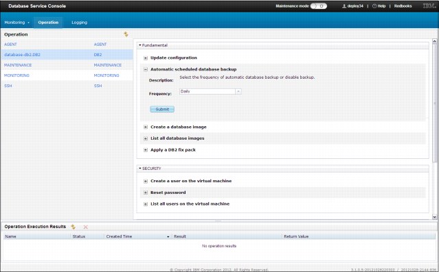
Figure 2-25 Database instance automatic backup setting
2.9.3 Creating a manual backup
The PureApplication System also provides a manual backup feature. This option requires configuring the Tivoli Storage Manager plug-in. This function is available by browsing to Virtual Application Console → Operation, then selecting the operation that you want to work with and clicking Create database images. Figure 2-26 shows from where the manual backup can be started. The interface for the stand-alone database instances is the same as the virtual application’s database.
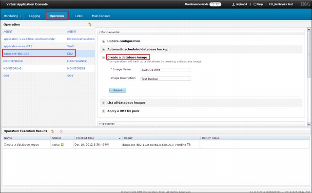
Figure 2-26 Manual database backup configuration
The system also provides a list of the existing database backup images. Figure 2-27 shows an example of this list. This list contains all database backup instances.
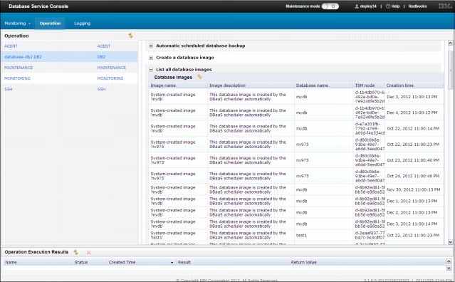
Figure 2-27 Existing database image backups
2.10 Export and import features
Although the development of the patterns is not complicated, the rebuilding of a well-functional system in a different environment can be a long process. Fortunately, PureApplication System also provides export and import functions.
The export and import features make it easier to perform the following tasks:
•Build a tested pattern in another system.
•Ensure matching of systems. In some cases, the exact pattern must be used in two systems and must be exported from one system and imported into another.
The GUI provides import and export options. However, another option is the use of the CLI, which can be more efficient in some cases.
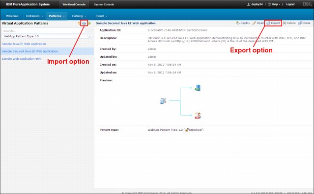
Figure 2-28 Sample virtual application pattern import and export feature
The CLI contains some sample scripts for pattern import and export features. These scripts are available in the pure.cli/samples directory in the pure.cli.zip file.
When more patterns or data migration is required, a best practice is to develop a CLI script to manage the process.
2.11 External database integration
PureApplication System provides predefined components for building virtual application patterns when an external DB2 database is used. This connection requires a working network link between the virtual application and the external database server. Every configuration option is available by using these predefined components.
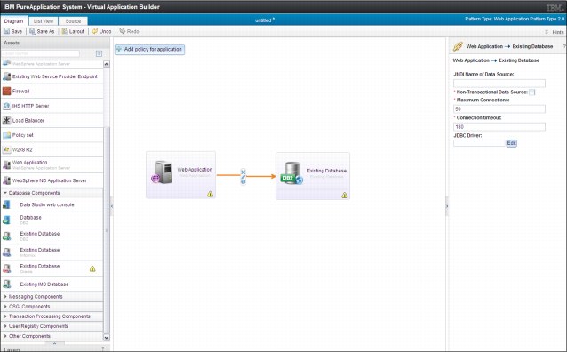
Figure 2-29 Diagram view of external database connection
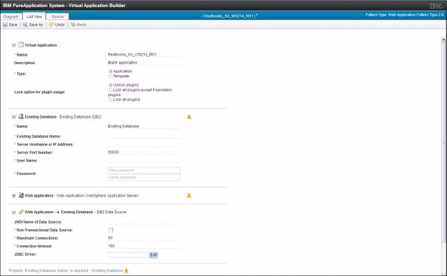
Figure 2-30 List view of external database connection parameters
2.12 Integrating shared network storage to virtual machines
The integration of external storage systems to the PureApplication System is not supported at the hypervisor level. The basic problem with this integration is system integrity. If we use any external device, the system cannot guarantee the integrity and performance of the infrastructure.
Physically, the system connects to the external network with an Ethernet interface. Although this connection excludes the SAN connection option, the system can communicate with other devices by using TCP/IP protocol. This configuration allows the connection to any external network file system. Although there are no options to integrate network resources with the hypervisor infrastructure, the deployed operation systems can connect and use those resources.
The implementation of this connection might be different at the virtual system and the virtual application level.
2.12.1 Network Access Server integration on virtual system level
The easiest way to make a reusable solution is the use of a simple script package that runs at server creation. This script can be added to every virtual server that must access an external file share.
|
Important: When you are developing scripts, the virtual machines can be restarted. Therefore, the script also needs to modify the operation system fstab file and mount the file system.
|
Figure 2-31 shows a sample script package implementation of a Network Access Server (NAS) connection.
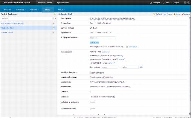
Figure 2-31 Sample NAS connection script package
2.12.2 NAS integration on virtual application level
The basic idea of file share integration in virtual applications is the same as with the virtual server-based solution. The main difference is the tool that is used for development. The most integrated solution for virtual applications is the Plug-in Development Kit (PDK). PDK is designed to help you build your own plug-ins.
2.12.3 iSCSI integration
The new operation system provides capabilities to use iSCSI volumes. Because iSCSI volumes use the TCP/IP protocol, they can be connected to virtual machines. The most important difference between NFS and iSCSI is the type of access. Every iSCSI volume has block level access and requires more caution in a cloud environment. The basic problem is the shared access. Most file systems cannot support the shared access. Considering this constraint, the implementation of an external iSCSI connection might be similar to the external NAS integration.
..................Content has been hidden....................
You can't read the all page of ebook, please click here login for view all page.