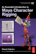
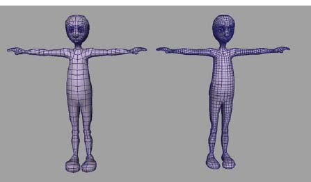
Creating Your First Biped Character: Modeling Basics
Characters, from left to right, by Katie Folsom, Ben Willis, Cheryl Cabrera, David Bokser, and Ryan Yokley.
Former Student Spotlight: Jeff Gill
Once upon a time, I submitted a demo reel to a respectable animation studio, and was lucky enough to sit with them as they critiqued my work face to face. In one segment, I had animated a free rig from the internet of a guy walking into a movie theater, eating popcorn, and reacting to what he saw on the screen. But rather than point out the flaws in my character’s animation, the two recruiters focused purely on the character’s design and the confusion it spawned over why anyone would enter a movie theater wearing nothing but a pair of underwear and some goggles. At the time I thought no one would look that deeply into the matter … after all, animations live in a world where anvils can fall from the sky without the slightest hint of reason.
However, when designing characters for animation, I’ve learned that it’s truly important to consider your audience. The simpler you design your characters, the less your audience will be distracted from the storytelling of your animation, which will then result in a greater finished product. Simpler designs are not only easier to rig/animate/model/you-name-it, but actually help to show line of action, which is key to any successful character driven piece.
So if it seems like a fun idea to model someone with an arrow jutting out the side of their head just because it looks cool, then go for it. But try keep in mind how your character will be animated and in what context they’ll be shown. After all, the last thing you’d want to do is spend several weeks of your life toiling over a beautiful animation, only to leave your audience wondering “how on earth would that guy put on a shirt without stretching out the neck hole?”
Jeff Gill is a graduate from the Savannah College of Art and Design with a BFA in Animation. His work has been screened throughout the world, including the Black Mariah Film Festival as well as the San Francisco International Film Festival, and has received numerous awards for online competitions, such as mtvU’s Best Animation on Campus and Firefox Flicks. For more information on Jeff or his work, visit: www.jeffgill.net
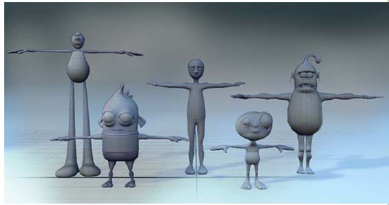
Snack attack by Jeff Gill (2006).
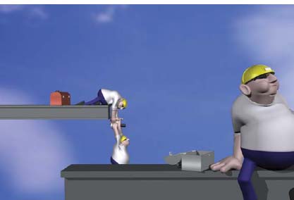
Character modeling workflow.
Modeling a character is an extensive process that can take many hours to complete. The modeling process will be easier and quicker to complete if you begin with a simple character design. When the design is more complicated, it will take longer to add the details. As with anything, the more you do something, the easier it becomes and the better you get at it. Practice makes perfect, right? So, don’t expect your first character model to become the one you animate. Take this time to explore the tools and begin learning how to problem solve your approach in order to achieve the desired shapes. Problem solving, after all, is the true heart of working successfully in 3D. Understand that your first try at modeling a character should be for practice and that you shouldn’t be afraid to scrap your experimentation and start again. You may discover that a second attempt will lead to a more satisfying result.
Be aware that the method of modeling a character that is explained in this chapter is only one approach, and that as a student, you should be exploring and figuring out what works best for you. There is never “the best way” or “the only way” but rather technique. Just as a fine artist develops his own style, you will find your own method. This approach analyzes the character’s body and breaks it down into simpler shapes that make up the whole. Just as a stone or wood sculptor roughs out their proportions first and refines the details later, we will begin with basic shapes before we add the details.
Work in X-ray Mode with Wireframe on Shaded
Because we are using NURBS planes to display our reference drawings, changing your display to wireframe mode by pressing (4) on the keyboard would cause the drawing to disappear. So, to resolve this, you can change your shaded mode by pressing (5) on the keyboard in your view panel under the SHADING menu and set the display to X-ray (which allows you to see through your model) with wireframe on shaded (which allows you to see the lines on the geometry). This is important so that you can see what you are doing when modeling and still see your reference drawings.
Object Mode and Component Mode
All geometry in Maya can be manipulated on several levels. In Object mode, you can select the entire piece of geometry and translate (move), rotate, and scale the whole thing. If you right click on top of the geometry, you will reveal a Marking menu of component levels, which allows you to manipulate finer details, much like a sculptor would manipulate clay. You can also turn on the component level in the Status Line or by pressing (F8).
NURBS, Polygons, or Subdivision Surfaces?
Which type of geometry should I use for my character? Many students ask me this question, and my advice is to work in either NURBS or Polygons or a combination of both, because subdivision surfaces can introduce other problems that lead to unpredictable results when bending and flexing during animation.
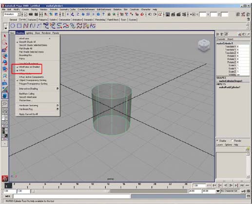
Turning X-ray mode on with wireframe on shaded in each view panel makes it easier to see what you are doing when you are modeling in Maya.
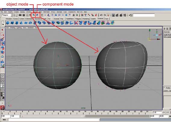
Object mode allows you to affect the ENTIRE piece of geometry, while component mode affects only a certain area.
The Status Line mode options.
In the approach that I am going to show you, the character will be modeled first using NURBS. The geometry can remain as NURBS. I have also included optional assignments to show you how to convert the NURBS surfaces to Polygons if you want to create a single seamless piece of geometry. It is important to note that your geometry does NOT need to be a single piece. It is perfectly fine to have separate pieces of geometry for each part of the body. It is also perfectly fine to have some pieces as polygons and others as NURBS surfaces. Once the skeleton and rig is complete, they will move together in unison when you are animating them.
There are endless ways to approach modeling, and Maya has many tools that can be used during this process. This chapter only covers the tools that I feel give you the easiest finished product and will be covered in the order that we will be using them. It is a good idea to read through this section first then refer back to the tool descriptions as you are working through the assignments.
Tools can be found in menu sets and shelves and will be indicated when each tool is discussed. Remember that the hotbox is a quick way of accessing your menu sets.
To display the hotbox, simply place your cursor anywhere in Maya and hold down the spacebar. Be sure to select [Hotbox Controls > Show All] to display all of the menu sets at once.
Each tool usually has several optional settings available. In order to prevent confusion and keep things simple, this chapter will only explain the options that will be used in the assignments. However, it is always a great idea to open the option boxes on all of these tools and explore the optional settings to see what they do.
![]()
ALWAYS work at the origin when modeling. The people who designed these tools assumed that modeling takes place at the origin.
Basic Toolbox
If you walk into a home improvement store and visit the tool section, you will notice a wide variety and range of equipment. Some tools are basic but get the job done (like a hammer and nails). Other tools are much more complicated and expensive but accomplish the same job (like a nail gun, which needs a compressor and special nails). Equipping yourself with the fancier tools is truly not necessary, because you can still hang a painting or build a house with a simple hammer and nail.
Maya is also full of tools. Just like the tools in the home improvement store, there are multiple tools that lead to the same goal. The first set of tools, which I have grouped into your basic toolbox, will be sufficient to model your character.
The following tools are used in combination to create your character’s head, neck and torso, arm, leg, eyes, hands, feet, hair, and other accessories (Assignment 2.1–2.7). Here is a brief explanation of those tools and how to find them.
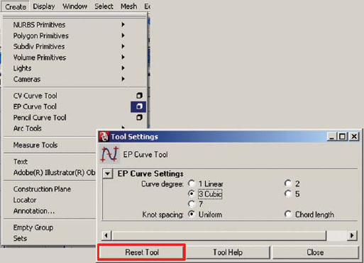
EP Curve Tool [Create > EP Curve Tool]
The EP Curve Tool creates curves by clicking a series of points, much like the game of connect the dots. The line that is created between the points will be a curve when using the default settings. A reference drawing can be traced using this tool to create a profile, or silhouette, curve.
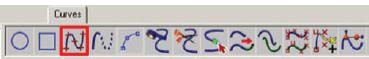
The EP Curve Tool can be found on the Curves shelf.
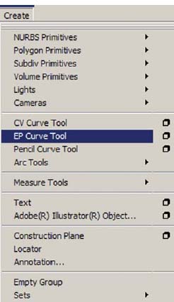
The EP Curve Tool can be found under the Create menu.
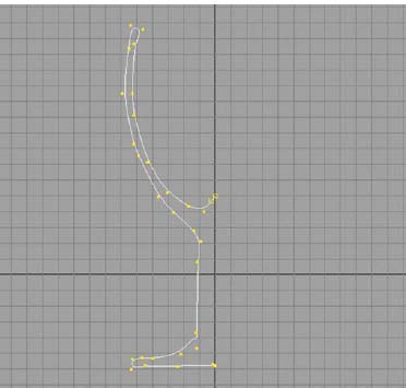
The profile curve of a wine glass created with the EP Curve Tool.
Revolve Tool [Surfaces > Revolve]
The Revolve Tool creates a surface around the chosen axis of a selected curve (such as the profile curve created with the EP Curve Tool). A NURBS surface is created by default around the Y axis, which works wonderfully for the head, neck, torso, and leg. The arm will need to be revolved around the X axis, which can be chosen by opening the option settings window.

The Revolve Tool can be found on the Surfaces shelf.
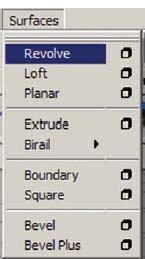
The Revolve Tool can be found in the Surfaces menu set by pressing (F4) on the keyboard under the Surfaces menu.
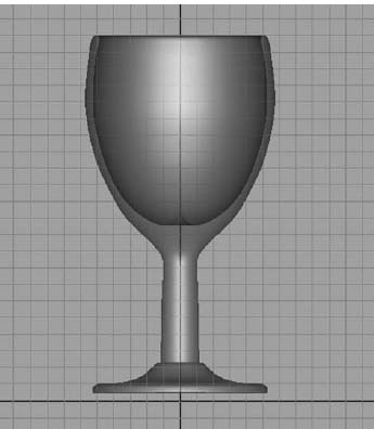
The surface of a wine glass created from the profile curve with the Revolve Tool.
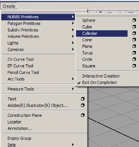
NURBS Cylinder [Create > NURBS Primitives > Cylinder]
A NURBS cylinder is not a tool, but rather a menu item that creates a surface in the shape of a cylinder (one of several primitive, or pre-built, pieces of geometry available in Maya). I list it here because it can be used to create your legs and arms, in lieu of using the EP Curve Tool and Revolve Tool. The cylinder is defined in sections (vertical lines) and spans (horizontal lines). The default settings will create a cylinder with only one span, so you must increase the number of spans to about twelve to allow the geometry to bend in areas such as the knees and elbows. You can change the spans in the option settings or in the input section of the channel box by clicking on makeNurbCylinder1, and changing the spans there. You can then scale and rotate the geometry into the place of the leg or arm.
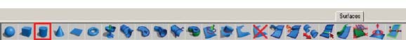
The NURBS cylinder can be found on the Surfaces shelf.
The NURBS cylinder can be found under the Create menu.
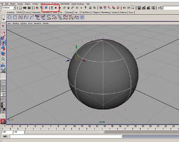
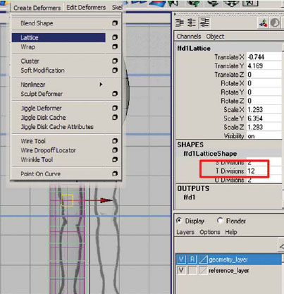
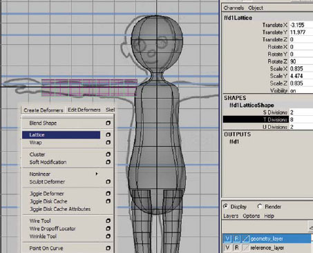
Lattice Deformer [Create Deformers > Lattice]
A deformer is a tool that is used to change the shape of an object and can be used during modeling to speed up the process on all types of geometry. Once created, a lattice deformer surrounds the geometry to be deformed and looks almost like scaffolding around a building. When moving a point on the lattice, the geometry it surrounds moves as well.
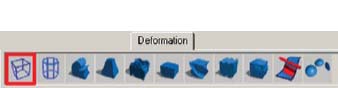
The Lattice Deformer can be found on the Deformation shelf.
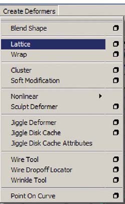
The Lattice Deformer can be found in the Animation menu set by pressing (F2) on the keyboard under the Create Deformers menu.
Much of the NURBS and polygonal modeling process relies on the ability to move points around to shape the geometry into the desired form. This can become a tedious procedure, so we want to minimize moving points as much as possible. The benefit of using a lattice (or any other deformer) is that it affects multiple points on the geometry at the same time, which speeds up your work.
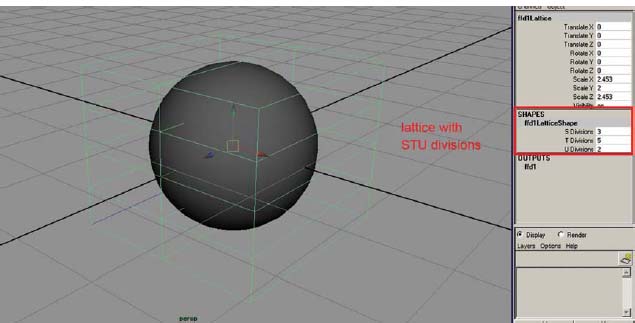
The Lattice Deformer applied to a Sphere. Notice there are 3 S divisions (left to right), 5 T divisions (top to bottom), and only 2 U divisions (front to back).
The STU divisions of the lattice can be added to or changed in the Shapes section of the channel box. STU is a special coordinate system for lattices (equivalent to XYZ where S = X, T = Y, and U = Z).
NURBS Sphere [Create > NURBS Primitives > Sphere]
A NURBS sphere is another primitive geometry shape, like the cylinder discussed earlier, and is often used as the beginning shape when modeling things such as eyes, hair, ears, and fingers. In order to shape the sphere, the default sections and spans will need to be increased, and should be evaluated on a case by case basis, depending on the detail needed for the object being modeled. Change the number of sections and spans in the option settings or in the input section of the channel box, click on makeNurbSphere1, and change them there. There is also a start sweep and end sweep which opens the sphere and can be used to create eyelids that blink.

The NURBS sphere can be found on the Surfaces shelf.
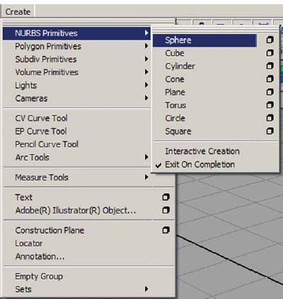
The NURBS sphere can be found under the Create menu.
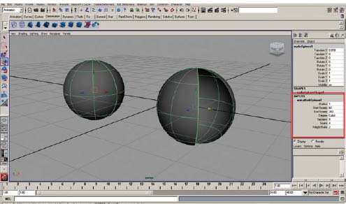
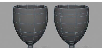
These NURBS spheres have 8 sections (vertical or longitude) and 4 spans (horizontal or latitude). The sphere on the right has a start sweep of 60 degrees, which opens the sphere.
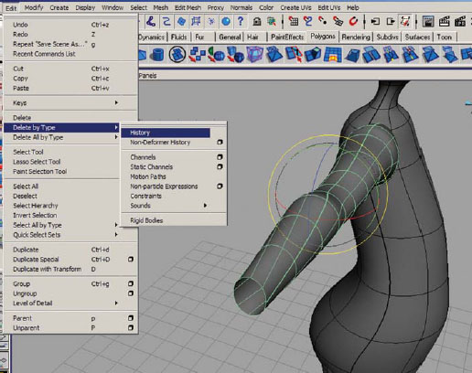
Construction History and Deleting History [Edit > Delete by Type > History]
As you build geometry in Maya, most of what you do to that geometry is added to a list and remembered by Maya so that you can alter an earlier step in the phase if needed. For example, after the revolved surface is created, you can still move the original points along the curve and the surface will automatically update its shape based on the new shape of the curve.
This list is referred to as construction history, and it can be seen in the input section of the channel box. While this can be handy, sometimes the current tool affecting the geometry can be interfered with by something done earlier in the modeling process. Because of this, it is important to delete the history often, especially when completing a major phase of the entire character creation process, such as when you are finished modeling and after you are finished texturing. Another rule of thumb that I follow is to delete the history if the current tool is yielding undesirable results. However, be aware that there are times that you want to KEEP your history, such as using a NURBS sphere to create an eyelid that blinks. Once it is deleted, there is no way to bring it back. It is wise to save a version of the scene file prior to deleting history if you are unsure.
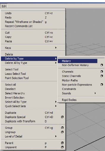
The command to delete History can be found under the Edit menu.
Inserting Isoparms [Edit NURBS > Insert Isoparms]
Isoparms are the lines that you see when a surface is selected. Additional isoparms can be added to the surface in order to create detail in the geometry, or to ensure adequate geometry in bend areas (such as elbows, knees, and the torso). When adding isoparms, be careful not to overdo it. Too many will result in heavy geometry, which will slow down animation and rendering. To insert a single isoparm, RMB (right mouse button) and hold over a surface (which brings up the marking menu), choose Isoparms (which brings you into component level), click and drag on an isoparm on the surface near to where you want to add one, drag it into position, then [Edit NURBS > Insert Isoparms].
![]()
The Insert Isoparms command can be found on the Surfaces shelf.
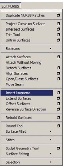
The Insert Isoparms command can be found in the Surfaces menu set by pressing (F4) on the keyboard under the Edit NURBS menu.
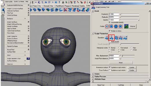
Sculpt Geometry Tool [Edit NURBS > Sculpt Geometry Tool – option box]
This tool is a much more artistic approach to modeling geometry. Using the artisan brush, you can paint on a surface wherever points exist to sculpt it by pushing, pulling, erasing, and smoothing. This tool is much more effective if using a pressure-sensitive tablet and pen. However, it is helpful for constructing noses and eye sockets, even with a mouse. This tool also affects polygonal and subdivision surfaces.
Adding additional Isoparms.

The Sculpt Geometry Tool can be found on the Surfaces shelf. It can also be found on the Polygons shelf and the Subdivisions shelf.
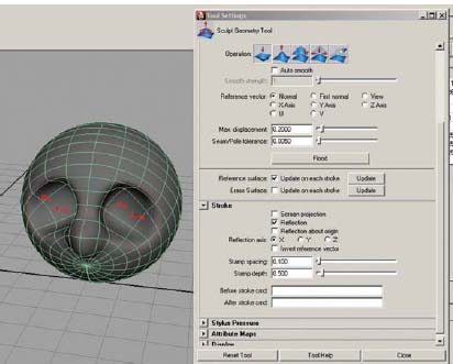
Using the Sculpt Geometry Tool to add facial details to a sphere.
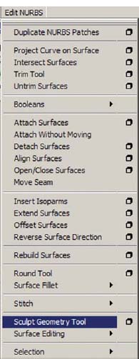
The Sculpt Geometry Tool can be found in the Surfaces menu set by pressing (F4) on the keyboard under the Edit NURBS menu.
Moving Individual CV
A control vertex, or CV is the point where two isoparms intersect. For some details and shapes, adjusting individual CV is the only way to reach the desired look. RMB and hold over a surface (which brings up the marking menu), choose CVs (which brings you into component level), click on a CV and use the move tool by pressing (w) on the keyboard to click drag the CV into position.
You can also choose component mode and select points in the selection mask area in order to easily select and move CVs.
Additional Tools for Your Toolbox
You can create an entire character from the tools discussed in Chapter 2 of the book, or if you would like to create a seamless character and have better control over texturing, you will need to convert your character into polygonal surfaces. The next set of menu items and tools can be used to achieve this goal. You can see by the length of this next section that there are many more tools needed for this process, and it will take more time to achieve the look desired.
![]()
Make sure your selection preferences are set to whole face!! Otherwise, you will always have to click on the little dot that appears in the center of the polygon. With this selected, you can click anywhere on the polygonal face to select it. (Go to [Window > Settings/Preferences > Preferences] and click on selection. Set the following: Polygon selection – whole face.)
When blocking in your model, remember that your polygonal faces should be as close to square shaped as possible. This will ensure that the geometry deforms better.
Polygonal Cube [Create > Polygon Primitives > Cube]
Like the NURBS primitives, Maya has several polygonal primitives available. Many modelers begin with the polygonal cube and create their entire seamless character from a single cube. This method is called box-modeling. This approach should be used to create the hands and feet if a single polygonal body is desired.
![]()
The Polygonal cube can be found on the Polygons shelf.
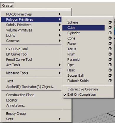
The Polygonal cube can be found under the Create menu.
Splitting Polygons [Edit Mesh > Split Polygon Tool]
This tool is great for dividing polygons to add more geometry when detail is needed. Be careful not to create Ngons in the process. Simply click on an edge (and drag with your mouse to position the first point) then click on another edge (and drag with your mouse to position the second point). Continue clicking on additional edges if necessary, until you have made the split desired. Then hit enter to complete the split.
The Split Polygon tool can be found on the Polygons shelf.
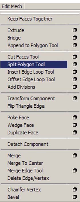
The Split Polygon tool can be found in the Polygons menu set by pressing (F3) on the keyboard under the Edit Mesh menu.
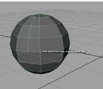
The Split Polygon tool.
![]()
Why quads?
When modeling in polygons, it is important to keep the faces as quadrilaterals (four sided polygons) and stay away from tris (three sided polygons) or Ngons (more than four sided polygons). There are several reasons for this. First, when texturing, you will have an easier time when unwrapping UVs (which is outside of the scope of this book). Second, when smoothing your character, you will avoid pinching that occurs in the presence of tris and Ngons. And third, if you are deforming your geometry, you will get nicer results.
Extrude Polygons [Edit Mesh > Extrude]
If faces or edges are selected in component mode, this tool allows you to pull those components out or push them in, while creating additional faces, which then builds the geometry into the desired shape.
If the faces are at an angle, the extrusion will be made at an angle. If you click on the little blue circle, you will change from local space to world space and your extrusion will then be made perpendicular to the graph.
Many modelers use the box modeling method and begin with a polygonal cube, then shape it roughly, and extrude the polygonal faces to form the torso and arms. I find as a beginner, this is a difficult method to use when trying to achieve an organic shape. For some reason, beginners do not spend enough time shaping the form with this method, and the end result remains too angular and not smooth.
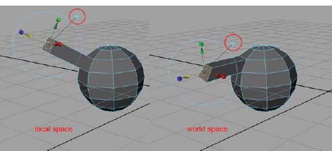
The Extrude Polygon tool has a little blue circle which toggles between world space and local space, changing the direction of the extrusion.
![]()
The Extrude Polygon command can be found on the Polygons shelf.
The Extrude Polygon tool can be found in the Polygons menu set by pressing (F3) on the keyboard under the Edit Mesh menu.
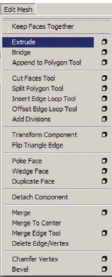
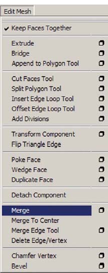
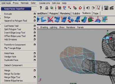
Keep Faces Together [Edit Mesh > Keep Faces Together]
If this option is unchecked, extruded faces will be separate pieces of geometry. This can be helpful, for example, when creating fingers from a palm. However, most of the time this option should be checked before extruding polygons or there will be interior faces as a result of polygonal faces that lie parallel to each other, which in turn, causes nonmanifold geometry.
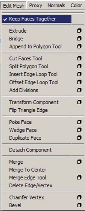
The Keep Faces Together option can be found in the Polygons menu set by pressing (F3) on the keyboard under the Edit Mesh menu.
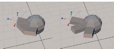
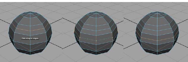
Extruding polygonal faces with Keep Faces Together option checked (left sphere) and extruding polygons with Keep Faces Together option unchecked (right sphere).
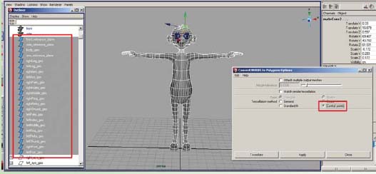
Converting NURBS to Polys [Modify > Convert > NURBS to POLYS]
This menu item will change an existing selected NURBS surface into polygonal geometry. It is perfectly fine to leave your models as NURBS surfaces. However, sometimes it is necessary to use polygons (creating one seamless piece of geometry or finer control in the texturing process), so this is a simple way of making them. Once converted, you can use other tools to make separate polygonal pieces into one.
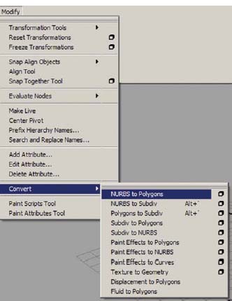
The NURBS to polys command can be found under the Modify menu.
It is extremely important to open the option box and change the tessellation method to control points in order to create clean polygonal geometry, as the default settings do not provide a usable result. It may be necessary to add additional Isoparms to the NURBS surface BEFORE converting to ensure organic shape is maintained once polygonal. However, realize the polygonal geometry will eventually be smoothed, and the addition of too many Isoparms will result in an extremely heavy model. Any overlapping NURBS surfaces may result in polygonal geometry that may need additional cleanup (deleting of faces and rebuilding).
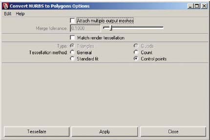
The Convert NURBS to polygons Options.
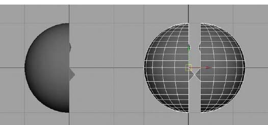
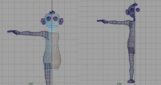
Delete Half of Your Model [RMB over geometry > FACES, select the faces and hit delete]
In order to save time, delete half of the character and model just one side. MAKE SURE that the points in the center of the character stay lined up with the origin. This will make MIRRORING the geometry over to the other side predictable. Otherwise, your mirrored side will not be even and result in a character that is wider than expected, or overlapping.
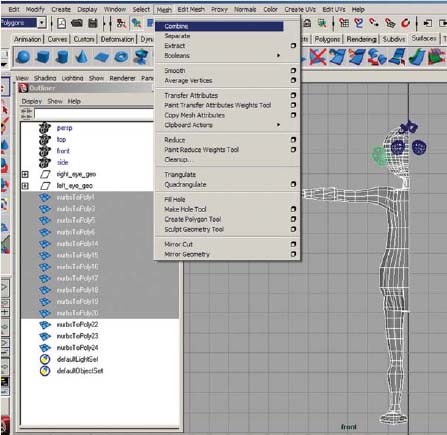
Combining Separated Polygonal Pieces into One [Mesh > Combine]
Once the NURBS surfaces have been converted into polygons, the polygons need to be combined and overlapping or extra faces need to be deleted. Combining polygons will make two or more polygonal surfaces act as one. HOWEVER, they are truly not one piece and can be separated again. You MUST merge vertices in order for the two surfaces to become one. Make sure to delete any overlapping faces, as these are not needed.
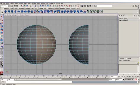
Selecting polygonal faces and deleting them to leave half of the object (in this image, half of a sphere.

The Combine command can be found on the Polygons shelf.
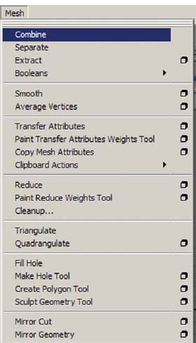
The Combine command can be found in the Polygons menu set by pressing (F3) on the keyboard under the Mesh menu.
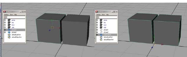
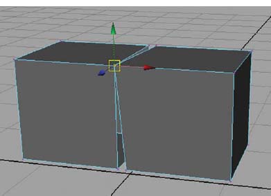
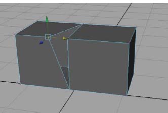
On the left are two separate polygonal cubes, on the right, they have been combined into polySurface1. Notice that the outliner still shows nodes pCube1 and pCube2 because of construction history.
Aligning Vertices with the Snap to Points Tool [Move tool and v hotkey]
After combining polygons and removing extraneous faces, the vertices should be snapped together to perfectly align the disjoined faces. Additional geometry may need to be added in order to have each face remain a quad and not become an Ngon. RMB over the surface and choose vertex. Select a point with the move tool, hold down the (v) key and MMB drag over the point you want to snap it to.
Snapping vertex points together using the Move tool and the (v) hotkey on the keyboard.
Closing Gaps or Holes [Edit Mesh > Append Polygon Tool]
After selecting this tool, pink arrows will appear on the edges of polygons that surround a hole or gap. Simply click on one edge, then click on another edge and hit the enter key to finish the process.
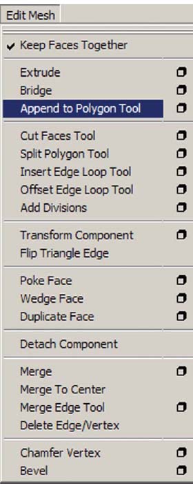
The Append Polygon tool can be found in the Polygons menu set by pressing (F3) on the keyboard under the Edit Mesh menu.
Inserting Additional Edges [Edit Mesh > Insert Edge Loop Tool]
This tool is used for dividing faces in order to create additional divisions in the geometry. It is really helpful when ensuring enough geometry in areas that bend, such has ankles, knees, hips, wrists, forearms, elbows, shoulders, the torso, and the neck.
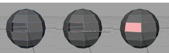
Creating a new polygon to fill a hole using the append polygon tool.
Again, be careful not to add too much geometry. Generally eight divisions around the length (such as vertical lines in the legs and torso and horizontal lines in the arms) are adequate. Five to seven cross divisions around each bend point is usually sufficient.
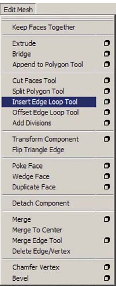
The Insert Edge Loop tool can be found in the Polygons menu set by pressing (F3) on the keyboard under the Edit Mesh menu.
The Insert Edge Loop tool inserts edges completely around the polygonal object.
Merging Vertices [Edit Mesh > Merge]
To ensure the faces actually become connected, the overlapping vertices are selected and merged. Your polygons MUST have been combined before you can merge vertices, otherwise it will not work. (There is no warning that this does not work. The only way to test is to click on a single vertex and move it around. Just make sure to undo by pressing (z) on the keyboard after testing.)
![]()
The Merge command can be found on the Polygons shelf.
Mirror Geometry [Mesh > Mirror Geometry]
Once you have half of the body modeled, you can simply mirror the geometry to obtain a complete model. HOWEVER, it is important to remember that all of the interior vertices must line up and be on the origin. If not, your mirrored geometry result will be undesirable. Make sure to open the option box and select the correct axis. If you have created your first half on the left side of the screen (your character’s right side) you can use the default settings. If you have created the character’s left side first, you would need to open the option box to change the axis appropriately, to negative X.
The Merge command can be found in the Polygons menu set by pressing (F3) on the keyboard under the Edit Mesh menu.
Clicking and moving a vertex that has been snapped on top of another shows that these two overlapping vertices are not merged together.
![]()
The Mirror Geometry command can be found on the Polygons shelf.
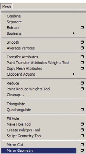
The Mirror Geometry command can be found in the Polygons menu set by pressing (F3) on the keyboard under the Mesh menu.
If any vertex points are not lined up with the origin, you will not achieve a desired mirror.
Showing Your Polygonal Normals [Display > Polygons > Face Normals]
During the process of modeling in polygons, you may notice some areas that appear darker than others. This is because your normals have been probably flipped inward. To confirm this, with the object selected, you can display your face normals using this menu command. To hide these again, simply repeat the command with the object selected: [Display > Polygons > Face Normals].
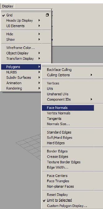
The Face Normals can be displayed using the command found under the Display menu. The polygonal object must be selected before applying this command. The Face Normals can be hidden again by applying the same command.
Making Sure All Normals Face in the Same Direction [Normals > Conform]
Once you can see the normals, you can select the entire object in object mode and use this menu item to make all of the normals face in the same direction. The direction that they face depends on the current majority.
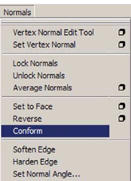
The Conform command can be found in the Polygons menu set by pressing (F3) on the keyboard under the Normals menu.
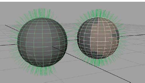
The sphere on the left has some normals that are flipped inside, the sphere on the right is the same sphere after the Conform command has been applied. You can see the selected faces have had their normals flipped back to the outside.
Making Sure All Normals Face toward the Camera [Normals > Reverse]
Sometimes, the CONFORM command does not always work. If this happens, you can select individual faces pointing inward and use this menu item to make them point outward.
If the CONFORM command makes all of the normals point inward (remember, it depends on the direction that the majority already faces), you can select the entire object in object mode and use this menu item to make all of the normals face outward.
Averaging the Distance Between the Normals [Normals > Average Normals]
Once you have all of the normals facing outward, you can select the entire object in object mode and use this menu item to average the distance between normals, which makes the geometry appear smoother without adding more physical geometry.
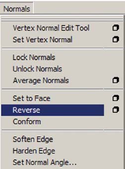
The Reverse command can be found in the Polygons menu set by pressing (F3) on the keyboard under the Normals menu.
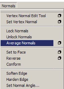
The Average Normals command can be found in the Polygons menu set by pressing (F3) on the keyboard under the Normals menu.
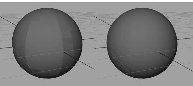
The sphere on the left has had normals flipped, which can cause the faces to be viewed sharply. The sphere on the right is the same sphere after the Average Normals command has been applied. Notice how much smoother the sphere on the right appears.
Smoothing [Mesh > Smooth]
By smoothing your polygonal geometry, the geometry becomes more organic in shape. This procedure adds divisions and rounds out the surface. THIS PROCEDURE SHOULD NOT BE DONE to your character at this stage of the character creation process because it adds too much geometry and causes the character model to become heavy and extremely difficult to work with, when creating blendshapes (Chapter 3) and in the skinning process (Chapter 8). If you want to see what your character will look like smoothed, make sure to UNDO by pressing (z) the smooth procedure before moving on.

The Smooth command can be found on the Polygons shelf.
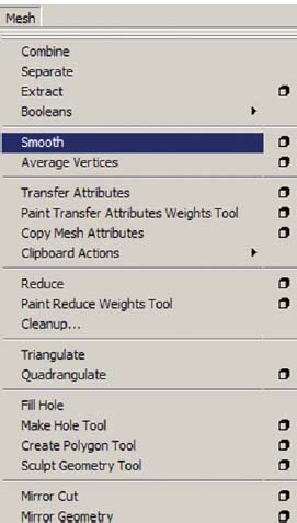
The Smooth command can be found in the Polygons menu set by pressing (F3) on the keyboard under the Mesh menu.
The character on the left is the low poly version, which doesn’t look very polished. The character on the right has been smoothed. MAKE SURE TO UNDO the smooth at this point by pressing (z) on the keyboard if you are testing to see your result.
You can preview what your model will look like when it is smoothed. With the polygonal object selected, press (2) on the keyboard to preview a smoothed polygonal object with a wireframe cage of the original. Press (3) on your keyboard to preview just the smooth polygonal object. Press (1) to turn off the preview and return back to the actual polygonal object.
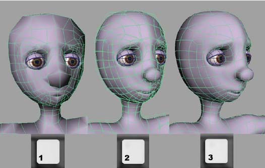
Previewing the smooth on a polygonal model.
![]()
Remember: As you work make sure to delete history and label your geometry. Check your outliner and hypergraph after deleting history to see what appears in the scene, and label your nodes appropriately.
Be sure to create a layer in the Layer Editor and add the character’s geometry to that layer.
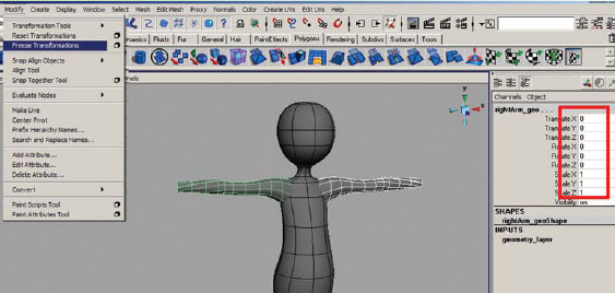
Make sure to freeze transformations on finished geometry to return the translation and rotation values to 0 and the scale values to 1.
Former Student Spotlight: Chris Grim
Character modeling is essentially the pedestal on which the animated short is built. Once the model is completed it will be rigged, animated and rendered out. A solid 3D short relies on one’s ability to correctly model topology and understand the esthetic look intended.
Producing a biped character from scratch can be a daunting task. The artist must create a visually appealing character that is “animatable” and will correctly deform during the rigging stage. The balance between esthetic form and function is a challenge in itself. In order to achieve a great model the artist must successfully mesh form with function. If either over powers the other, the 3D short will suffer.
Within my work on character development, I noticed my skills improving at different rates. As my ability to create esthetically pleasing characters improved, my knowledge of topology and deformation was only a step behind. It is important that you have a strong knowledge in both aspects in order to create a beautiful model that can be animated correctly.
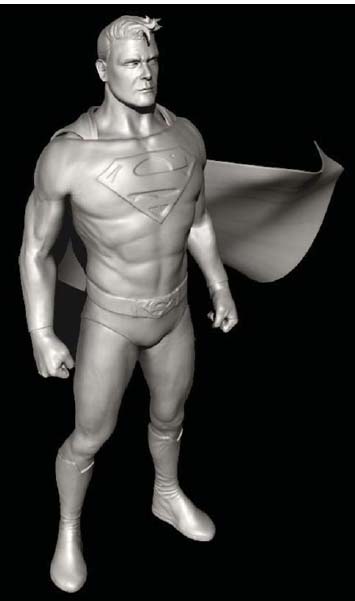
Superman by Chris Grim (2006).
Chris Grim received his BFA from Savannah College of Art and Design with honors and is currently finishing his MFA in animation. In 2006, he was awarded an honorable mention for modeling by Rhythm and Hues. He completed an internship at Gentle Giant Studios and after graduating, started working for Blur Studios. His work can be viewed at: www.chrisgrim.com.
2.1 Once again, we are reminded to KEEP IT SIMPLE. The simpler the character design, the easier it will be to model character.
2.2 Don’t be afraid to explore tools and experiment. Sometimes it is best to scrap your first attempt and start over.
2.3 While working, it is suggested to use X-ray mode and wireframe on shaded so that you can see what you’re doing while modeling.
2.4 Object mode and component mode are generally the two levels that are used during the character creation process. Object mode allows you to affect the entire object, while component mode allows you to manipulate finer details, or pieces of the object.
2.5 The type of geometry, NURBS, polygons, or subdivision surfaces, used for your character model truly does not matter. However, subdivision surfaces can still be unreliable when performing during animation.
2.6 The EP Curve Tool creates curves by clicking a series of points, which then creates a line between the points.
2.7 The Revolve Tool creates a surface around the chosen axis of the selected curve, such as a profile curve created with the EP Curve Tool.
2.8 A NURBS cylinder is a primitive object that can be used to create other shapes.
2.9 A lattice deformer surrounds the object with a type of scaffolding, which can then be manipulated to change the shape of an object.
2.10 A deformer is used to speed up the process of modeling because it affects multiple points of geometry at the same time.
2.11 A NURBS sphere is another primitive object that can be used as a base to create other shapes.
2.12 Construction history is a list of processes used on an object during modeling. It is sometimes needed, but often it must be deleted. So that tools work predictably, construction history should be deleted often.
2.13 The Sculpt Geometry Tool provides an artistic approach to modeling and can be used on all types of geometry.
2.14 Sometimes the only way to get the desired shape when modeling is to move individual CVs.
2.15 To make polygons easy to select, change your selection preferences to whole face.
2.16 When modeling with polygons, make sure that the faces are square shaped. This provides deformation during the animation process.
2.17 A polygonal cube is a primitive object that is generally the starting point for a method called box modeling.
2.18 The Split Polygon Tool can be used to divide up the polygonal faces during the modeling process.
2.19 When modeling in polygons is important to keep faces as quadrilaterals, or four sided.
2.20 During the box modeling process, extrude polygons is used often as a tool to create more faces.
2.21 It is important to have the option for Keep Faces Together checked while extruding except in cases when the faces need to be separate such as in the fingers.
2.22 NURBS surfaces can be converted to polygonal surfaces in order to create one seamless piece of geometry. Make sure to convert using control points as the setting for the tessellation method.
2.23 When working with polygonal geometry, it can be more efficient to only model half of the character and mirror the geometry for the other side.
2.24 Separate pieces of polygonal geometry must be combined before the vertex points can be merged.
2.25 Vertex points can be aligned easily by holding down the (v) hot key on the keyboard while moving them.
2.26 The append polygon tool is perfect for filling gaps or holes in polygonal geometry.
2.27 The Insert Edge Loop Tool will divide polygonal faces completely around the entire piece of geometry.
2.28 Two overlapping vertices can be combined into one by using the merge command. Remember, if merging vertices on two separate pieces of geometry, they must first be combined.
2.29 When mirroring geometry, it is important to make sure that none of the interior vertices have crossed the origin line.
2.30 All polygonal normals should face outwards. Normals can be flipped during the modeling process. You can display them and then use some of the normal tools to flip them back out, if necessary.
2.31 Whilst smoothing the polygonal geometry may be desired, it should not be done at this point of the workflow. Simply press (3) on the keyboard for a smooth preview.
2.32 As you work, make sure to delete history and labeled geometry.
2.33 When completing your geometry, create a layer in the Layer Editor and add the character geometry to that layer.
2.34 Freeze transformations on finished geometry.
Assignments: Modeling a Character
When modeling a character in 3D space, it is important to make sure that your character faces front in the front view, side in the side view, and down in the top view in order for all of the tools to work appropriately. The programmers created the character tools in Maya to work with your character facing in the positive Z direction.
Assignment 2.1: Model a Head, Neck and Torso
1. Open Maya and set your project.
a. Go to [Start > Programs] and select Maya.
b. Once Maya is open go to [File > Project > Set…] and browse to your project folder then click “OK”.
2. Open your last saved file: go to [File > Open] and select 01_referenceImages.ma.
3. Set all four view panels to X-ray mode and wireframe on shaded.
a. Turn on hardware texturing (press 6) on the keyboard so that you can see your reference images.
b. In the top view panel, go to [Shading > X-Ray], and then [Shading > Wireframe] on shaded.
c. In the perspective view panel, go to [Shading > X-Ray], and then [Shading > Wireframe] on shaded.
d. In the front view panel, go to [Shading > X-Ray], and then [Shading > Wireframe] on shaded.
e. In the side view panel, go to [Shading > X-Ray], and then [Shading > Wireframe] on shaded.
4. Draw a profile curve of your character’s head, neck and torso. If your character has clothing, it should be part of this profile curve. Clothing does not need to be separate, unless your character is going to change clothing in the animation.
a. Go to [Create > EP Curve Tool] and open the option box, click Reset Tool and close the option box.
b. In the front window, trace your drawing by clicking points along the outline on the right side of your character (your left side), starting at the center of the head and ending in the crotch. Hit enter when finished. Ignore the arms for now.
c. You can adjust the positions of the points on the curve by RMB on top of the curve and choose Control Vertex. Use your move tool by pressing (w) to select points and move them around to refine the shape of your curve. You can also delete extra points by selecting them and hitting the delete key.
Create > EP Curve Tool.
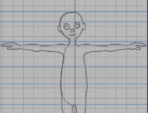
Tracing your drawing with the EP Curve Tool. An X marks each click of the mouse and becomes a point on the curve.
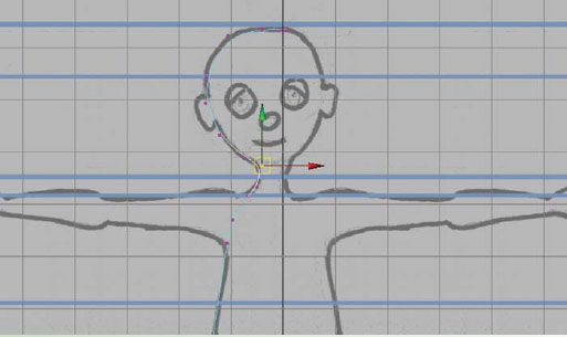
Refining the curve by adjusting the positions of the points on the curve with the move tool.
5. Create the surface for your character’s head, neck and torso.
a. Select curve1, the curve you created, and go to [Surfaces > Revolve]. This process creates revolvedSurface1, a NURBS surface in the shape of the profile curve.
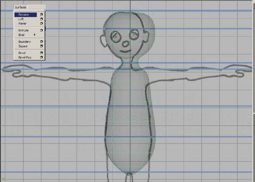
Creating the surface for you character’s head and torso using the revolve command.
b. Open the outliner [Window > Outliner] and select curve1, the curve you created. In the perspective view panel, RMB to the left of the curve (in a blank area of the window NOT touching the curve or the surface) and choose Control Vertex (this will show the CV points only on the curve). Use your move tool by pressing (w) on the keyboard to select points and move them around to refine the shape of your surface. Because Maya has construction history, each operation you perform is connected to the preceding operation, and moving the points on the curve will automatically affect the surface and change its shape.
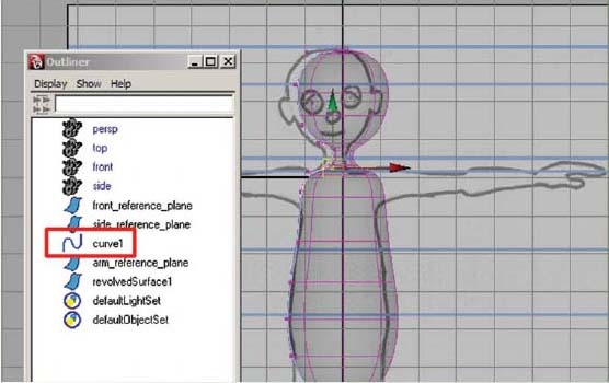
Refining the surface by adjusting the positions of the points on the curve with the move tool.
c. Select revolvedSurface1, go to [Create Deformers > Create Lattice] and with the lattice selected, in the Shapes section of the channel box, increase the T divisions from 5 to about 10–14.
d. In the side view panel, RMB on top of the lattice and choose Lattice Point. Use your move tool by pressing (w) on the keyboard to click drag (or marquee drag) over points on the lattice (this ensures that you are selecting the points on both sides of the lattice) and move them around to refine the shape of your surface. In the perspective view panel, continue to move and scale (if adjusting 2 or 4 points on the same row) the points on the lattice to refine the shape of your surface. Your reference drawings are just a reference. Feel free to make artistic changes while modeling in order to achieve the look you want.
e. Select revolvedSurface1 then go to [Edit > Delete by Type > History]. This will remove the lattice, but any changes that have been made are now permanent. This also removes the connection to curve1.
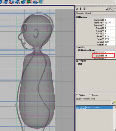
Adding a lattice deformer to your head and torso shape. Using a lattice allows even distribution and the changes to affect the entire piece of geometry.
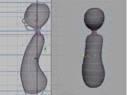
Refining the surface by adjusting the positions of the lattice points with the move and scale tools.
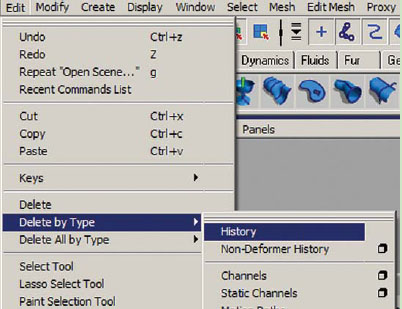
Edit > Delete by type > History.
f. In the outliner, select curve1 and hit delete.
g. Select revolvedSurface1 and rename to body_geo by clicking on the name and typing in the channel box.
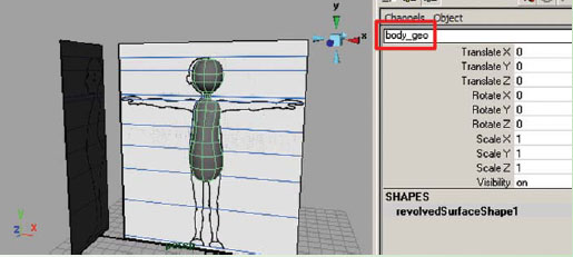
Renaming the torso and head shape in the channel box.
h. In the Layer Editor of the channel box, create a new layer. Double click on the new layer (layer1) and rename this layer geometry_layer, then click save. Select body_geo, RMB click and hold on top of the geometry_layer and choose Add Selected Objects. To make the objects non-selectable, click in the empty box between the V (visibility) and the layer name. An R (reference) should appear. This keeps any objects assigned to a layer visible but not selectable.
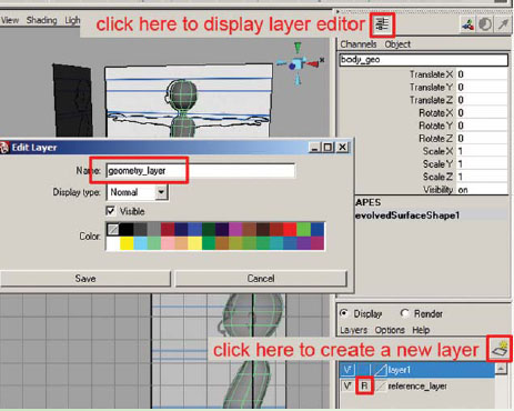
Click on the “create a new layer” button in the Layer Editor and rename it geometry_layer.
6. Save your scene file.
a. Go to [File > Save as]. This should open the scenes folder of your project (assuming you set the project as in step 1).
b. Name your scene 02_asgn01_body_geo.ma.
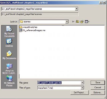
Saving and naming your scene 02_asgn01_body_geo.ma.
1. Open Maya and set your project.
a. Go to [Start > Programs] and select Maya.
b. Once Maya is open go to [File > Project > Set…] browse to your project folder and click OK.
2. Open your last saved file. Go to [File > Open] and select 02_body_geo.ma.
3. Continue working in X-ray mode and wireframe on shaded.
4. Go to [Create > NURBS Primitives > Interactive Creation] to uncheck this option and turn it off. (Interactive creation allows you to click and drag on the grid to create the size and shape of a primitive.)
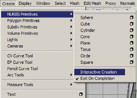
Turning off interactive creation.
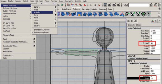
5. Create a NURBS cylinder [Create > NURBS Primitives > Cylinder].
a. Move and scale the cylinder over the character’s right leg.
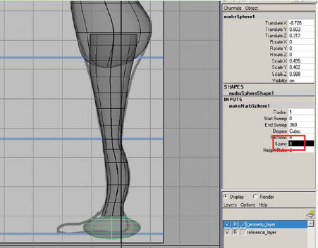
b. In the INPUTS section of the channel box, click on makeNurbCylinder1 and change Spans to 12.
6. With the NurbCylinder1 still selected, create a Lattice Deformer [Create Deformers > Lattice].
a. With the lattice selected, in the Shapes section of the channel box, increase the T Divisions from 5 to about 12.
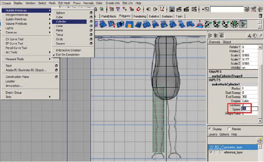
Creating a NURBS cylinder, positioning it for the leg, and dividing it for adequate deformation later.
Adjusting the lattice for additional divisions. Using a lattice allows even distribution and the changes to affect the entire piece of geometry.
b. In the front view panel, RMB on top of the lattice and choose Lattice Point. (You may need to RMB in the perspective window if your lattice is close to the geometry, in order to see the correct marking menu.) Starting at the hip area, in the front view panel, use your move tool by pressing (w) on the keyboard to click drag (or marquee drag) over points on the lattice (this ensures that you are selecting the points on both sides of the lattice) and move them around to refine the shape of your surface. Then starting at the hip area, in the side view panel, continue to move the points on the lattice to refine the shape of your surface. Make sure to check the shape in the perspective window. Your reference drawings are just a reference. Feel free to make artistic changes while modeling in order to achieve the look you want.
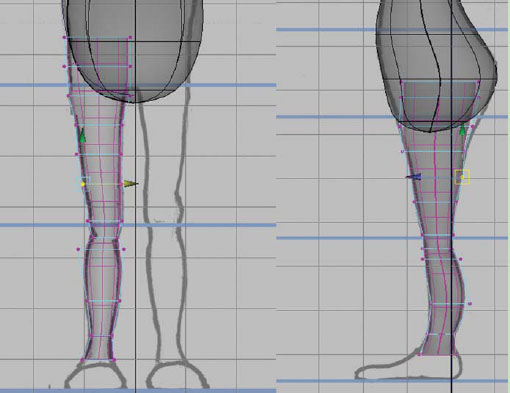
Refining the shape of the leg by adjusting the positions of the lattice points with the move and scale tools.
c. Select NurbCylinder1 then go to [Edit > Delete by Type > History]. This will remove the lattice but any changes that have been made are now permanent.
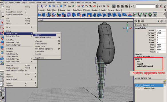
Deleting history to remove the lattice and bake the changes to the shape of the cylinder.
d. Rename NurbCylinder1 to rightLeg_geo by clicking on the name and typing in the channel box.
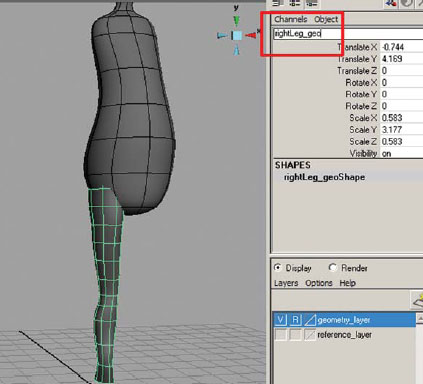
Keep your scene organized by labeling your geometry appropriately.
e. Duplicate rightLeg_geo [Edit > Duplicate] or press (ctrl + d) on the keyboard. In the channel box, rename rightLeg_geo1 to leftLeg_geo, change the TranslateX value to positive (which positions the leg onto the other side of the origin) and change the ScaleX value to negative (which makes the leg invert).
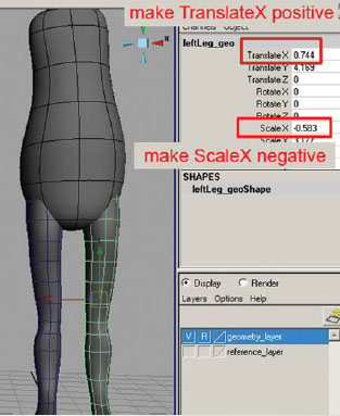
Duplicating the geometry and changing the ScaleX value to the negative inverts the shape. Changing the TranslateX value to positive positions the leg evenly on the opposite side of the origin.
f. Select rightLeg_geo and leftLeg_geo [Modify > Freeze Transformations]. Freeze transformations on finished geometry will return the translation and rotation values to 0 and the scale values to 1.
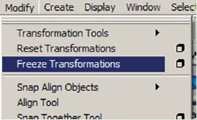
Freezing transformations makes the geometry transformation values return to 0 for translations and rotations and 1 for scale.
g. In the Layer Editor of the channel box, RMB click and hold on top of the geometry_layer and choose “Add Selected Objects”.
7. Save your scene file.
a. Go to [File > Save as]. This should open the scenes folder of your project (assuming you set the project as in step 1).
b. Name your scene 02_asgn02_leg_geo.ma.
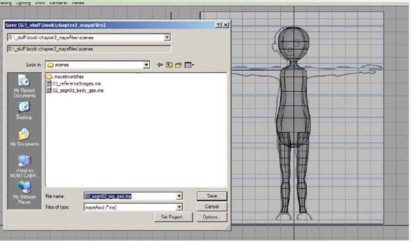
Saving and naming your scene 02_asgn02_leg_geo.ma.
Assignment 2.3: Model an Arm
1. Open Maya and set your project.
a. Go to [Start > Programs] and select Maya.
b. Once Maya is open go to [File > Project > Set…] browse to your project folder and click OK.
2. Open your last saved file. Go to [File > Open] and select 02_asgn02_leg_geo.ma.
3. Continue working in X-ray mode and wireframe on shaded.
4. Continue working with Interactive Creation unchecked [Create > NURBS Primitives > Interactive Creation]
5. Create a NURBS cylinder. [Create > NURBS Primitives > Cylinder].
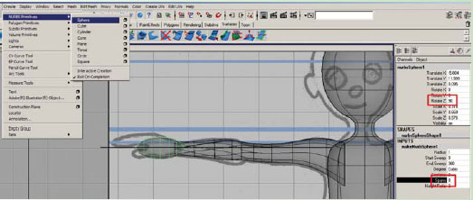
a. In the channel box, change RotateZ to 90.
b. Move and scale the cylinder over the character’s right arm.
c. In the INPUTS section of the channel box, click on makeNurbCylinder1 and change Spans to 10.
Creating a NURBS cylinder, positioning it for the arm, and dividing it for adequate deformation later.
6. With the NurbCylinder1 still selected, create a Lattice Deformer [Create Deformers > Lattice].
a. With the lattice selected, in the Shapes section of the channel box, increase the T divisions from 5 to about 8.
Adjusting the lattice for additional divisions. Using a lattice allows even distribution and the changes to affect the entire piece of geometry.
b. Starting at the shoulder area, in the front view panel, RMB on top of the lattice and choose Lattice Point. (You may need to RMB in the perspective window if your lattice is close to the geometry, in order to see the correct marking menu.) In the front view panel, use your move tool by pressing (w) on the keyboard to click drag (or marquee drag) over points on the lattice (this ensures that you are selecting the points on both sides of the lattice) and move them around to refine the shape of your surface. Then starting at the shoulder area, in the top view panel, continue to move the points on the lattice to refine the shape of your surface. Make sure to check the shape in the perspective window. Your reference drawings are just a reference. Feel free to make artistic changes while modeling in order to achieve the look you want.
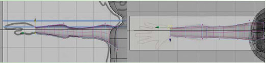
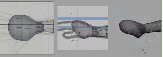
Refining the shape of the arm by adjusting the positions of the lattice points with the move and scale tools.
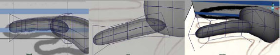
c. Optional: For better deformation in the forearm later, you can rotate the last three rows of lattice points incrementally to total 45 degrees forward (starting with the row closes to the elbow, rotate slightly, then the next row, and the row at the wrist should have the points even again.) To see what I am talking about, hold your arm out parallel to the floor and palm forward, then rotate your arm so that the palm is facing the floor, Notice how your skin moves with your forearm during this rotation.
Rotating the forearm for better deformation when the hand twists.
d. Select NurbCylinder1 then go to [Edit > Delete by Type > History]. This will remove the lattice but any changes that have been made are now permanent.
e. Rename NurbCylinder1 to rightArm_geo by clicking on the name and typing in the channel box.
Deleting history to remove the lattice and bake the changes to the shape of the cylinder, then renaming the geometry appropriately.
f. Duplicate rightArm_geo [Edit > Duplicate] or press (ctrl+d) on the keyboard. In the channel box, rename rightArm_geo1 to leftArm_geo, change the TranslateX value to positive (which positions the arm onto the other side of the origin) and change the ScaleY value to negative (which makes the arm invert).
g. Select rightArm_geo and leftArm_geo [Modify > Freeze Transformations]. Freeze transformations on finished geometry will return the translation and rotation values to 0 and the scale values to 1.
h. In the Layer Editor of the channel box, RMB click and hold on top of the geometry_layer and choose Add Selected Objects.
Freezing transformations on the arm geometry.
7. Save your scene file.
a. Go to [File > Save as]. This should open the scenes folder of your project (assuming you set the project as in step 1).
b. Name your scene 02_asgn03_arm_geo.ma.
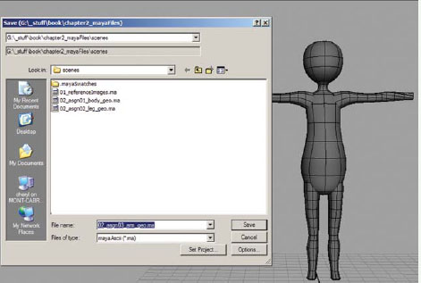
Saving and naming your scene 02_asgn03_arm_geo.ma.
Assignment 2.4: Model a Hand
1. Open Maya and set your project.
a. Go to [Start > Programs] and select Maya.
b. Once Maya is open go to [File > Project > Set…] browse to your project folder and click OK.
2. Open your last saved file. Go to [File > Open] and select 02_asgn03_arm_geo.ma.
3. Continue working in X-ray mode and wireframe on shaded.
4. Continue working with Interactive Creation unchecked [Create > NURBS Primitives > Interactive Creation].
5. Create a NURBS sphere [Create > NURBS Primitives > Sphere].
a. In the channel box, change “RotateZ” to 90.
b. Move and scale the sphere over the character’s right palm.
c. In the INPUTS section of the channel box, click on makeNurbSphere1 and change Spans to 8.
Creating a NURBS cylinder, positioning it for the palm, and dividing it for adequate deformation.
6. With the NurbSphere1 still selected, create a Lattice Deformer [Create Deformers > Lattice].
a. Starting at the wrist area, in the front view panel, RMB on top of the lattice and choose Lattice Point. (You may need to RMB in the perspective window if your lattice is close to the geometry, in order to see the correct marking menu.) In the front view panel, use your move tool by pressing (w) on the keyboard to click drag (or marquee drag) over points on the lattice (this ensures that you are selecting the points on both sides of the lattice) and move them around to refine the shape of your surface. Then starting at the wrist area, in the top view panel, continue to move the points on the lattice to refine the shape of your surface. Make sure to check the shape in the perspective window. Your reference drawings are just a reference. Feel free to make artistic changes while modeling in order to achieve the look you want.
b. Select NurbSphere1 then go to [Edit > Delete by Type > History]. This will remove the lattice, but any changes that have been made are now permanent.
c. Rename NurbSphere1 to rightPalm_geo by clicking on the name and typing in the channel box.
Adjusting the lattice for additional divisions and reshaping the lattice to make the sphere into a palm.
7. Create another NURBS sphere. [Create > NURBS Primitives > Sphere].
a. In the channel box, change “RotateZ” to 90.
b. Move and scale the sphere over the character’s right index finger.
c. In the INPUTS section of the channel box, click on makeNurbSphere1 and change Spans to 8.
8. With the NurbSphere1 still selected, create a Lattice Deformer [Create Deformers > Lattice].
a. Starting at the palm area, in the front view panel, RMB on top of the lattice and choose Lattice Point. (You may need to RMB in the perspective window if your lattice is close to the geometry, in order to see the correct marking menu.) In the front view panel, use your move tool by pressing (w) on the keyboard to click drag (or marquee drag) over points on the lattice (this ensures that you are selecting the points on both sides of the lattice) and move them around to refine the shape of your surface. Then starting at the palm area, in the top view panel, continue to move the points on the lattice to refine the shape of your surface. Make sure to check the shape in the perspective window. Your reference drawings are just a reference. Feel free to make artistic changes while modeling in order to achieve the look you want.
Making the index finger.
b. Select NurbSphere1 then go to [Edit > Delete by Type > History]. This will remove the lattice but any changes that have been made are now permanent.
c. Rename NurbSphere1 to rightIndex_geo by clicking on the name and typing in the channel box.
9. Repeat steps 7–8 for each finger and the thumb, renaming them rightMiddle_geo, rightRing_geo, rightPinky_geo, and rightThumb_geo.
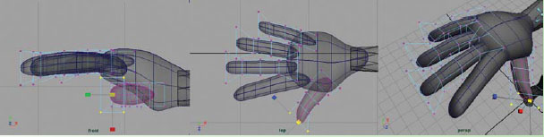
Making the fingers and thumb.
10. Duplicate the hand for the left side.
a. Select rightPalm_geo and duplicate [Edit > Duplicate] or press (ctrl+d) on the keyboard. In the channel box, rename rightPalm_geo1 to leftPalm_geo, change the TranslateX value to positive (which positions the arm onto the other side of the origin) and change the ScaleY value to negative (which makes the palm invert).
11. Repeat this process for each finger.
12. Select rightPalm_geo, rightIndex_geo, rightMiddle_geo, rightRing_geo, rightPinky_geo, rightThumb_geo, leftPalm_geo, leftIndex_geo, leftMiddle_geo, leftRing_geo, leftPinky_geo, and leftThumb_geo [Modify > Freeze Transformations]. Freeze Transformations on finished geometry will return the translation and rotation values to 0 and the scale values to 1.
13. In the Layer Editor of the channel box, RMB click and hold on top of the geometry_layer and choose Add Selected Objects.
14. Save your scene file.
a. Go to [File > Save as].
b. Name your scene 02_assgn04_hand_geo.ma.
Assignment 2.5: Model a Foot
1. Open Maya and set your project.
a. Go to [Start > Programs] and select Maya.
b. Once Maya is open go to [File > Project > Set…] browse to your project folder and click OK.
2. Open your last saved file. Go to [File > Open] and select 02_asgn04_hand_geo.ma.
3. Continue working in X-ray mode and wireframe on shaded.
4. Continue working with Interactive Creation unchecked [Create > NURBS Primitives > Interactive Creation].
5. Create a NURBS sphere [Create > NURBS Primitives > Sphere].
a. Move and scale the sphere over the character’s right foot.
b. In the INPUTS section of the channel box, click on makeNurbSphere1 and change Spans to 6.
Creating a NURBS sphere, positioning it for the foot, and dividing it for adequate deformation.
6. With the NurbSphere1 still selected, create a Lattice Deformer. [Create > Deformers > Lattice].
a. In the Shapes section of the channel box, change the T divisions to 2 and the U divisions to 5.
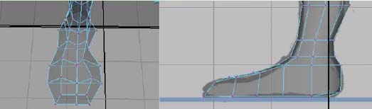
Starting at the ankle area, in the side view panel, RMB on top of the lattice and choose Lattice Point. (You may need to RMB in the perspective window if your lattice is close to the geometry, in order to see the correct marking menu.) In the front view panel, use your move tool by pressing (w) on the keyboard to click drag (or marquee drag) over points on the lattice (this ensures that you are selecting the points on both sides of the lattice) and move them around to refine the shape of your surface. Check the shape in the perspective window. Reshape the front of the foot. Your reference drawings are just a reference. Feel free to make artistic changes while modeling in order to achieve the look you want.
b. Select NurbSphere1 then go to [Edit > Delete by Type > History]. This will remove the lattice, but any changes that have been made are now permanent.
c. Rename NurbSphere1 to rightFoot_geo by clicking on the name and typing in the channel box.
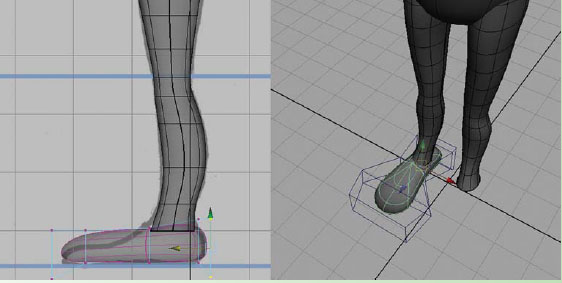
Adjusting the lattice for additional divisions and reshaping the lattice to make the sphere into a foot.
d. Select rightFoot_geo and duplicate [Edit > Duplicate] or press (ctrl+d) on the keyboard. In the channel box, rename rightFoot_geo1 to leftFoot_geo, change the TranslateX value to positive (which positions the foot onto the other side of the origin) and change the ScaleX value to negative (which makes the foot invert).
e. Select rightFoot_geo and leftFoot_geo [Modify > Freeze Transformations]. Freeze transformations on finished geometry will return the translation and rotation values to 0 and the scale values to 1.
f. In the Layer Editor of the channel box, RMB click and hold on top of the geometry_layer and choose Add Selected Objects.
g. Save your scene file: Go to [File > Save as].
h. Name your scene 02_asgn05_foot_geo.ma.
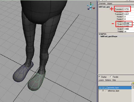
Duplicating the right foot to create the left foot.
Assignment 2.6: Model Eyes
1. Open Maya and set your project.
a. Go to [Start > Programs] and select Maya.
b. Once Maya is open go to [File > Project > Set…] browse to your project folder and click OK.
2. Open your last saved file. Go to [File > Open] and select 02_asgn05_foot_geo.ma.
3. Continue working in X-ray mode and wireframe on shaded.
4. Continue working with Interactive Creation [Create > NURBS Primitives > Interactive Creation].
5. Turn your geometry_layer to invisible by clicking and hiding the V next to the layer.
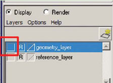
Turn the geometry layer invisible by hiding the V in the Layer Editor.
6. Go to [Create > NURBS Primitives > Sphere – option box]. Change the Axis to Z and the Spans to 6. Click Create.
7. Rename NurbSphere1 to eyeball_geo by clicking on the name and typing in the channel box.
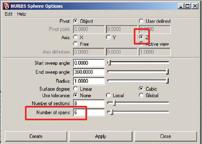
The NURBS sphere option box.
8. Hold your cursor over the sphere and RMB, click and hold, select [Assign New Material > Phong] (Phong is a reflective material when rendered. You may want to try a different material to achieve your desired look.) The attribute editor will open. Rename the material eye_phong.
a. In Attribute Material window, click on the checkered square next to the Color. Create Render Node will appear. Select 2D Textures – Ramp. Press (6) to see how the material looks on the Sphere.
b. Change the Ramp Attribute Type to a U Ramp.
c. Click on the blue circle of color, then click on the blue box in the Selected Color section, this opens the color picker where you can change the color to a very dark blue, almost black. You really should never use black, as black is very flat and creates a visual death on the screen.
d. Click on the red circle of color, then click on the red box in the Selected Color section, this opens the color picker where you can change the color to a very pale orange, almost white. For the same reasons as black, you really should never use white either.
e. Click on the green circle of color, then click on the green box in the Selected Color section, this opens the color picker where you can change the color to the color chosen for your character’s eye color. You will also need to click inside of the ramp rectangle to create a fourth circle of color, which allows you to make your eyes two toned for more interest.
f. Click and drag the circles up and down to adjust their position. The closer the circles are to each other, the sharper the edge of color.
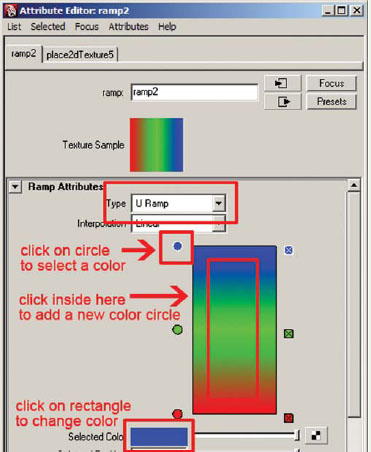
Adjusting the ramp attributes.
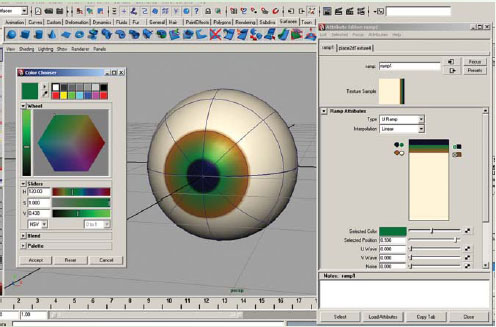
Adjusting the ramp colors to make an eye shader.
![]() Don’t be afraid to add more detail or your own ideas. For example, all eyes have a thin dark ring around the outside of the iris called a limbus line. You could add this detail because it also adds quite of bit of visual interest.
Don’t be afraid to add more detail or your own ideas. For example, all eyes have a thin dark ring around the outside of the iris called a limbus line. You could add this detail because it also adds quite of bit of visual interest.
9. Go to [Create > NURBS primitives > Sphere – option box] Change the Axis to X, the Start sweep angle to 55, and the End sweep angle to 355. Click Create.
10. In the channel box, in the INPUTS section, click on the makeNurbSphere which reveals additional attributes including Start Sweep and End Sweep, which will allow your character to blink. You can test this out by clicking on the WORD Start Sweep, then click and drag the MMB (middle mouse button) in a view panel to see the eye blink. Make sure to undo this motion by pressing (z) on the keyboard.
a. Rename NurbSphere1 to eyelid_geo by clicking on the name and typing in the channel box.
b. In the channel box, change RotateX to 206 (your value may be different), and ScaleX, ScaleY, ScaleZ to 1.02.
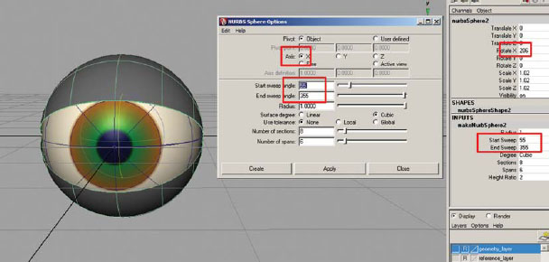
Creating another NURBS sphere for the eyelid.
c. Add dimension to the eyelid. Add a couple additional horizontal isoparms to the eyelid. To insert a single isoparm, RMB and hold over a surface (which brings up the marking menu), choose Isoparms (which brings you into component level), click and drag on an isoparm on the surface near to where you want to add one, drag it into position, then [Edit NURBS > Insert Isoparms].
d. RMB on top of the eyelid and choose HULLS.
e. Select a hull near the edge of the upper eyelid, then shift select a hull near the edge of the lower eyelid.
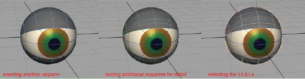
Inserting isoparms and selecting the HULLS.
f. RMB on top of the eyelid and choose Control Vertex.
g. Hold down the ctrl key and drag select each pole to deselect it.
h. Use the scale tool to scale out a lip around the edge of the eyelid.
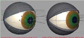
Reshaping the eyelid to add dimension.
i. If you want to reshape your eye to something other than spherical, you can now add a lattice. Select both eyeball_geo and eyelid_geo, then [Create Deformers > Lattice].
i. Open the outliner and select both fftd1Lattice and fftd1Base. You will need to scale these up so that reshaping them doesn’t cause intersection problems between the eyelid and eyeball when the eyelid closes.
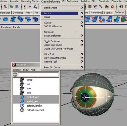
Adding a lattice deformer to the eye and eyelid.
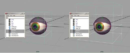
Scaling both the lattice and the base larger.
ii. You can reshape the lattice by RMB on the lattice and moving the lattice points with the move tool by pressing (w) on the keyboard. If the eyeball starts to intersect the eyelid, you can scale the eyelid up slightly.
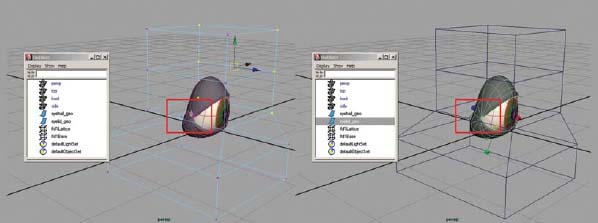
Exposing part of the eyeball while reshaping the lattice (left) can be alleviated by scaling the eyelid slightly larger (right).
j. Open the outliner, [Windows > Outliner] Select the eyeball_geo, eyelid_geo, fftd1Lattice, and fftd1Base and (if you have a Lattice and Base) ctrl + g to group them together. Rename group1 to right_eye_geo by clicking on the name and typing in the channel box.
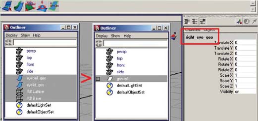
Grouping the eye parts and renaming the group to right_eye_geo.
k. Turn your geometry_layer to visible by clicking on the first empty box and V will appear next to the layer.
l. Select the right_eye_geo group in the outliner and move the eye into place. You can also scale this group if necessary. Adjust the lattice if needed as well, once the EYE GROUP is in position. Make sure that you do not move the individual pieces of the eye, as this will cause problems when the eye needs to rotate later.
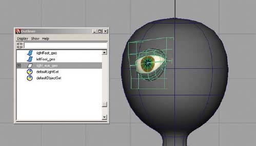
Repositioning the right_eye_group.
m. Duplicate the eye [Edit > Duplicate Special – option box]. Check Duplicate input graph. Rename right_eye_geo1 to left_eye_geo. This keeps the input (makeNurbSphere) which is necessary for blinking.
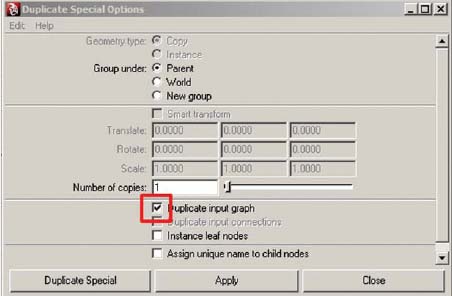
The Duplicate Special option box with the Duplicate input graph option checked.
n. Change the TranslateX value of left_eye_geo to positive (which positions the eye onto the other side of the origin) and change the ScaleX value to negative (which makes the eye invert).
o. Select both lattice and hide them by pressing (ctrl + h).
p. DO NOT FREEZE TRANFORMATIONS OR DELETE HISTORY on your eyes. Doing so will remove the shape changes and the lattice, as well as the INPUTS for makeNurbSphere which is needed to create eye blinks.
q. Select right_eye_geo and left_eye_geo. In the Layer Editor of the channel box, RMB click and hold on top of the geometry_layer and choose Add Selected Objects.
11. Save your scene file.
a. Go to [File > Save as].
b. Name your scene 02_asgn06_eye_geo.ma.
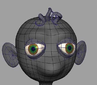
Assignment 2.7: Adding Detail to the Face
You can continue to add additional spheres that are shaped by lattices to create the nose, mouth, and eyebrows. The technique that follows shows how to create those features and keep them as part of the head, instead of separate geometry.
1. Open Maya and set your project.
a. Go to [Start > Programs] and select Maya.
b. Once Maya is open go to [File > Project > Set…] browse to your project folder and click OK.
2. Open your last saved file. Go to [File > Open] and select 02_asgn06_eye_geo.ma.
3. Continue working in X-ray mode and wireframe on shaded.
4. Continue working with Interactive Creation [Create > NURBS Primitives > Interactive Creation].
5. To add detail to the head:
a. Add a couple additional vertical isoparms where the eyes would be. To insert a single isoparm, RMB and hold over a surface (which brings up the marking menu), choose Isoparms (which brings you into component level), click and drag on an isoparm on the surface near to where you want to add one, drag it into position, then [Edit NURBS > Insert Isoparms].
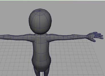
Adding an isoparm.
b. Add additional horizontal isoparms as needed. You can add multiple isoparms at the same time by RMB and hold over a surface, choose Isoparms, and shift selecting two isoparms. Open the [Edit NURBS > Insert Isoparms – option box]. Choose Between Selections and then type in the # of isoparms to insert.
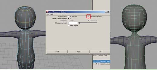
Adding additional isoparms using the option for between selections.
c. Use the Sculpt Geometry Tool [Edit NURBS > Sculpt Geometry Tool – option box] to pull out a nose for your character.
Creating a nose shape.
d. With the view panel active, hold the mouse over the surface, hold down the “b” key and MMB click and drag to interactively adjust the size of the brush.
e. You can use the reflection option under the Stroke tab for creating the same changes on both sides of the face at once. This can be helpful for pulling out eyebrows. Also make sure you reduce the maximum displacement from 1 to 2 so that the eyebrows are not pulled out as far.
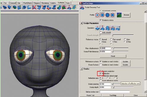
Use the reflection option to create eyebrows.
f. Continue to add ISOPARMS as necessary to create the detail necessary. The more detail you want, the more isoparms are needed.
g. RMB over the geometry and choose Control Vertex in order to select CVs in the mouth area and pull them into make a mouth.
6. Save your scene file.
a. Go to [File > Save as]. This should open the scenes folder of your project (assuming you set the project as in step 1).
b. Name your scene 02_asgn07_faceDetail_geo.ma.
Optional Assignment 2.8: Model Ears, Hair, and Accessories
This is an optional assignment, as not all characters have hair or ears. However, the ears a can change the appearance of your character and add an element that allows for character, personality, and a way of conveying expression.
This is not a step by step tutorial. Rather, you can use techniques learned so far to create ears and hair. A simple way of creating an ear is to begin with a sphere on the Z axis with 8 spans, position it near the head and scale it on the X axis to create the proper thickness. Add a lattice deformer, and reshape the lattice points to create an ear. Delete history and duplicate for the other side, changing the TranslateX value to positive, the ScaleX to negative, and rotate to position as needed.
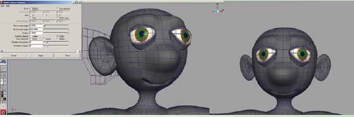
Creating an ear using a NURBS sphere.
A similar approach using a NURBS sphere and a lattice can be used to create the hair.
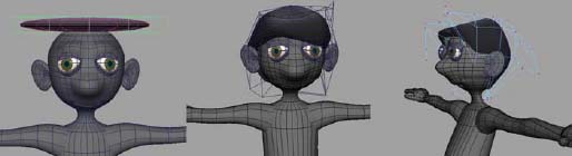
Creating hair using a NURBS sphere.
Try experimenting with a NURBS cone and nonlinear deformers, such as bend and twist. Make sure to add adequate spans to the cone BEFORE adding the deformer, so that the geometry will bend properly.
Curly hair using a NURBS cone.
Accessories, such as hats, ties, and other props can be modeled in similar ways. Hats, for example, can be created using a profile curve and revolving a surface, much like we did for the head and neck.
Optional Assignment 2.9: Combining Everything into a Single Polygonal Shape with Additional Approaches to Modeling Hands and Feet
1. Open Maya and set your project.
a. Go to [START > PROGRAMS] and select Maya.
b. Once Maya is open go to [File > Project > Set …] browse to your project folder and click OK.
2. Open your last saved file. Go to [File > Open] and select 02_asgn07_faceDetail_geo.ma.
3. Continue working in X-ray mode and wireframe on shaded.
4. Select all the body geometry. Use the outliner [Window > Outliner] or the hypergraph [Window > Hypergraph: Hierarchy] to verify that all body geometry is selected. Do not select the eyes and eyelids.
[Modify > Convert > NURBS to POLYS] except for the eyes and eyelids.
5. Delete history on all converted polygons. [Edit > Delete by Type > History].
6. Delete NURBS geometry except for the eyes and eyelids.
Converting NURBS to polygons.
7. Delete half of your model [RMB over geometry > FACES, select the faces and hit delete] all except the eyes and hair, if any.
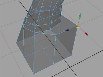
8. With the geometry still selected, combine separate polygonal pieces into one [Mesh > Combine].
Selecting half of the faces of your polygonal face and torso.
Note: You may want to review the box modeling section that follows for the hands and feet. It is easier to delete the NURBS geometry at this time rather than deleting the polygonal faces after combining.
Combining all polygonal surfaces into one.
9. Delete history on polySurface1 and rename polySurface1 to body_geo.
10. Determine if there are equal numbers of edges on the two areas that need to be attached, and add additional geometry where needed. [Edit Mesh > Insert Edge Loop Tool]. Click on an edge and drag the new edge into place.
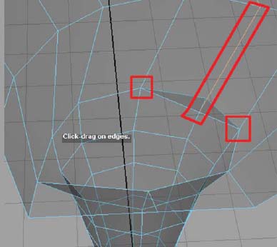
Add a new edge in order to align the torso with the leg.
11. Delete any overlapping geometry RMB over the geometry, choose FACES, select the faces that you want to remove and hit the DELETE key.
12. Using the move tool by pressing (w) on the keyboard hold down the ‘v’ key and move snap vertex points to line up with the other point nearby.
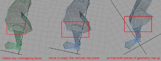
Aligning the torso vertices with the leg vertices.
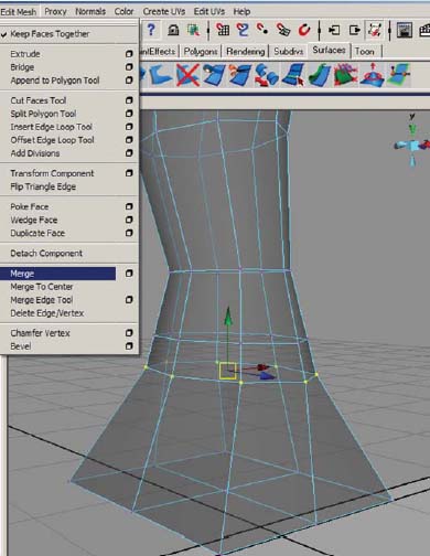
13. Select the row of overlapping vertices and merge vertices. [Edit Mesh > Merge].
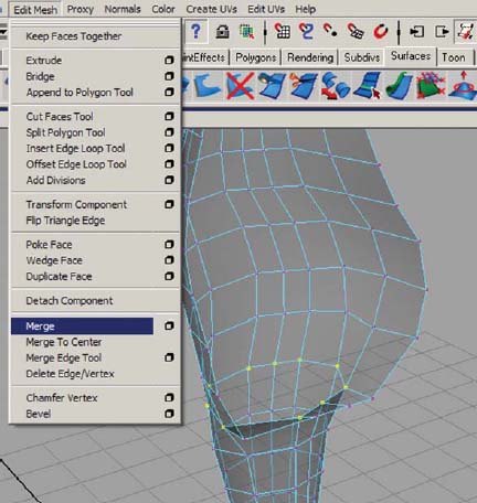
Merging the overlapping vertices.
14. Save your scene file: Go to [File > Save as].
15. Name your scene 02_asgn09_01_convert_to_polys_geo.ma.
You can repeat the process of deleting overlapping geometry, adding additional edges, v snapping vertex points, and merging vertices for each separate body part. However, in the case of the foot and the hand, it is easier to delete the existing parts and remodel them using the box modeling technique as shown in the following tutorials. Remember, deleting the foot and hand should be done BEFORE combining polygonal surfaces, as it is more difficult to select the overlapping geometry then it is to delete an entire, uncombined object.
Tutorial 2.9.a: Box Modeling a Foot
1. If you have not deleted the foot as suggested earlier, remove the existing foot geometry if it was converted and combined. RMB over the foot geometry, choose FACES, select the faces that you want to remove and hit the DELETE key.
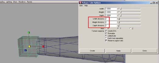
2. Create a polygonal cube [Create > Polygon Primitives > Cube – option box] and divide the width and depth to 2. Reposition it to where the foot should be, scaling as needed.
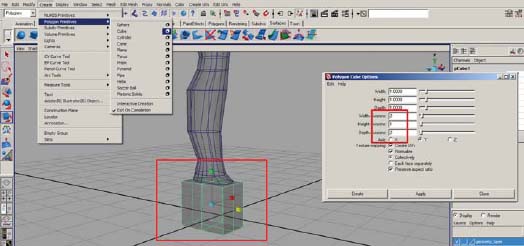
Creating a polygonal cube to become the foot.
3. RMB over the cube, choose FACES, and select the top faces and hit the DELETE key.
4. Select the cube, shift select the body_geo, and combine them into one piece [Mesh > Combine].
5. RMB over the cube, and choose VERTEX. Using the move tool by pressing (w) on the keyboard hold down the ‘v’ key and select a vertex to move snap vertex points to line up with the other point nearby.
Snapping the vertices of the cube to those of the leg.
6. Delete history on polySurface1 and rename polySurface1 to body_geo.
7. Select the row of overlapping vertices and merge vertices [Edit Mesh > Merge].
Merging the overlapping vertices of the foot and leg.
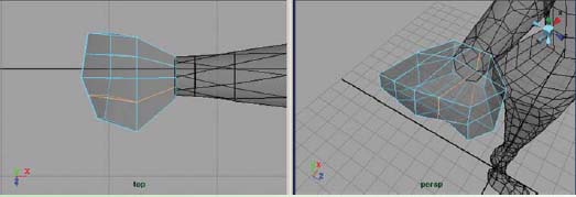
8. In the SIDE view panel, RMB over the foot geometry, choose VERTEX, select and move the bottom row of vertices to line up with your reference drawing.
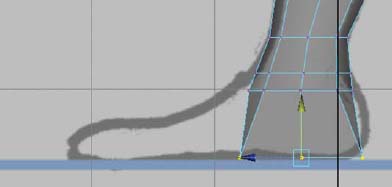
Adjusting the bottom row of vertices.
9. RMB over the foot geometry, choose FACES. In perspective view panel, select the two front faces and go to [Edit Mesh > Extrude]. Click on the little blue circle, and drag the arrow forward which will extrude your polygons in world space, perpendicular to the graph. Do not extrude all the way to the tip of the foot, rather, extrude only about a third of the way there.
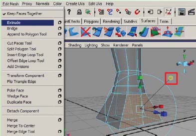
Extruding the foot parallel can occur if first clicking on the blue circle (shown yellow in this image because it is already selected) then clicking on the arrow to drag the extrusion forward.
10. Hit the (g) key to extrude again, and click on the blue circle before dragging the arrow forward, about halfway to the tip of the foot.
11. Hit the (g) key to extrude again, and click on the blue circle before dragging the arrow forward, to the tip of the foot.
12. RMB over the foot geometry, choose VERTEX, and use the move tool to reshape the vertices into the shape of the foot. Be sure NOT to cross the origin line.
Reshaping the extruded faces into a foot.
Tutorial 2.9.b: Box Modeling a Hand
1. If you have not deleted the hand as suggested earlier, remove the existing hand geometry if it was converted and combined. RMB over the hand geometry, choose FACES, select the faces that you want to remove and hit the DELETE key.
2. Create a polygon cube and divide the width, height and depth to 2 and reposition it to where the hand should be, scaling as appropriate.
Creating a polygonal cube to become the hand.
3. RMB over the cube, choose FACES, and select the side faces closest to the wrist and hit the DELETE key.
4. In the FRONT and TOP view panel, RMB over the hand geometry, choose VERTEX, select and move the vertices to line up with your reference drawing.
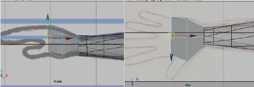
Reshaping the cube into a palm.
5. Determine where the fingers will be and add additional geometry where needed [Edit Mesh > Insert Edge Loop Tool]. Click on an edge and drag the new edge into place (It might be a great idea to limit your character’s fingers to a thumb and two fingers for the first time you create one, as it takes additional time to create and control four fingers and a thumb).
Adding additional edges to divide the geometry for fingers.
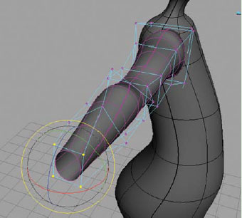
6. Extrude the fingers:
a. Before we extrude the fingers, we want to make sure we get separate faces during the extrusion. Make sure to uncheck [Edit Mesh > Keep Faces Together] RMB over the hand geometry, choose FACES. In perspective view panel, select the faces where the fingers will be.
Making sure Keep Faces Together is unchecked.
b. [Edit Mesh > Extrude] In the TOP view panel, drag the arrow forward which will extrude your polygons. Do not extrude all the way to the tip of the fingers; rather, extrude only about a third of the way there (to the first knuckle). Then click on one of the scale boxes.
c. Then click on the center scale box, and MMB click and drag to scale the fingers slightly and separate the end faces. This will make it easier to reposition the vertices because they will not be overlapping.
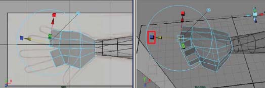
Extruding the fingers to the first knuckle.
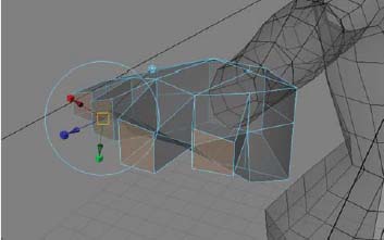
Scaling the extrusion to separate the fingers.
d. Using the move tool by pressing (w) on the keyboard, in the TOP and FRONT view panel, reposition the end row of vertices for each finger.
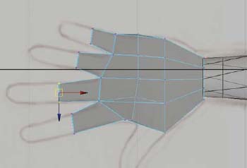
Adjusting the positions of the finger geometry.
e. RMB over the hand geometry, choose FACES. In perspective view panel, select the end faces of each finger and go to [Edit Mesh > Extrude]. In the TOP view panel, drag the arrow forward which will extrude your polygons. Do not extrude all the way to the tip of the fingers; rather, extrude only about a half of the way there (to the second knuckle).
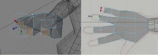
Extruding the fingers to the second knuckle.
f. Using the move tool by pressing (w) on the keyboard, in the TOP and FRONT view panel, reposition the end row of vertices for each finger.
g. RMB over the hand geometry, choose FACES. In perspective view panel, select the end faces of each finger and go to [Edit Mesh > Extrude].
h. In the TOP view panel, drag the arrow forward which will extrude your polygons, all the way to the tip of the fingers.
i. Using the move tool by pressing (w) on the keyboard, in the TOP and FRONT view panel, reposition the end row of vertices for each finger.
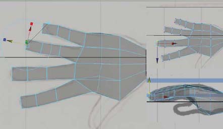
Extruding the fingers to the tip.
7. Extrude the thumb:
a. RMB over the hand geometry, choose FACES. In perspective view panel, select the face where the thumb will be and go to [Edit Mesh > Extrude].
b. In the TOP view panel, drag the arrow forward which will extrude your polygons. Do not extrude all the way to the tip of the thumb; rather, extrude only about a half of the way there (to the first knuckle).
c. Using the move tool by pressing (w) on the keyboard, in the TOP and PERSPECTIVE view panel, reposition the end row of vertices for the thumb.
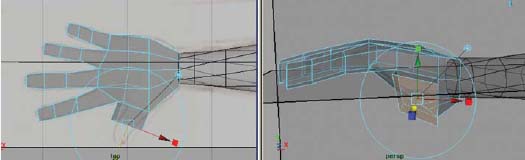
Extruding the thumb to the first knuckle.
d. RMB over the hand geometry, choose FACES. In perspective view panel, select the end face of the thumb and go to [Edit Mesh > Extrude].
e. In the TOP view panel, drag the arrow forward which will extrude your polygons all the way to the tip of the thumb.
f. Using the move tool by pressing (w) on the keyboard, in the TOP and PERSPECTIVE view panel, reposition the end row of vertices for the thumb.
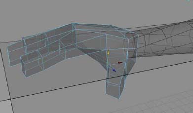
Extruding the thumb.
8. Combine the hand with the existing body_geo:
a. Determine if there are equal numbers of edges on the two areas that need to be attached, and add additional geometry where needed [Edit Mesh > Insert Edge Loop Tool]. Click on an edge and drag the new edge into place.
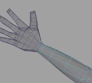
Inserting a new edge in order to align the arm with the hand.
b. In object mode – press (F8) on the keyboard, with the selection tool – press (q), select the hand, shift select the body_geo, and combine them into one piece [Mesh > Combine].
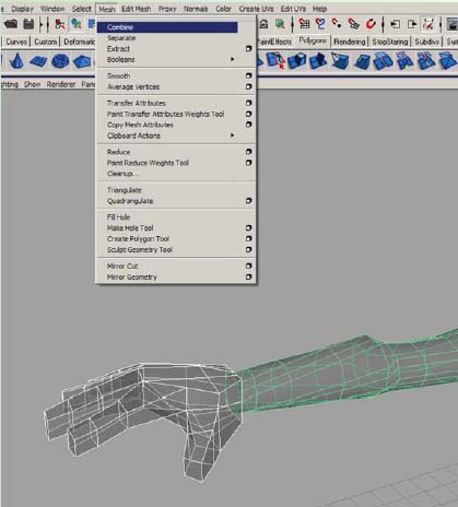
Combining the hand and body geometry.
c. RMB over the hand, choose VERTEX, then RMB over the arm and choose VERTEX. Using the move tool by pressing (w) on the keyboard, hold down the ‘v’ key and select a vertex to move snap vertex points to line up with the other point nearby.
d. Select the row of overlapping vertices and merge vertices [Edit Mesh > Merge].
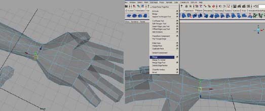
Aligning the hand and arm vertices, then merging them.
e. Delete history on polySurface1 and rename polySurface1 to body_geo.
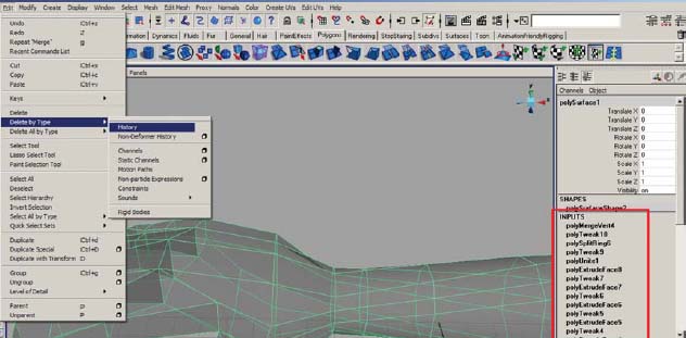
Deleting construction history.
9. Save your scene file: Go to [File > Save as]. Name your scene 02_asgn09_02_convert_to_polys_geo.ma.
Ears and hair will also need to be deleted and remodeled using the box modeling approach, as this method is less tedious than trying to combine the spheres and cones originally used in the NURBS model with the polygonal topology of the head. It is perfectly fine to keep the hair separate. It really depends on how much time you want to dedicate to your model. Do not combine any accessories, such as ties or hats. These geometry pieces should remain separate so that they can be removed or controlled independently from the character’s body.
Once you have combined everything into one half of your character, you will want to create the other side. Make sure that all of the interior vertices are lined up on the origin. When you mirror, you will notice immediately if there is a problem. You will probably need to delete the faces at the top of the head, near the pole, and then append them using [Edit Mesh > Append Polygon Tool]. Click on one edge, then click on another edge and hit the Enter key to finish the process. Remember to keep everything as quadrangles. In order to do this, you may also need to use the [Edit Mesh > Split Polygon Tool].
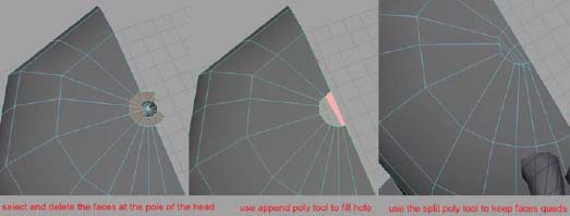
Fixing the pole at the head into fewer quads.
1. Select body_geo and go to [Mesh > Mirror Geometry].
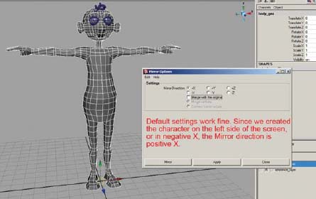
Mirroring the right side to create the left side.
2. Pay close attention to the mouth area. You may need to separate the vertices (using the move tool) before merging so that they do not merge the mouth shut in the center, then reposition them after the mirror is successful.
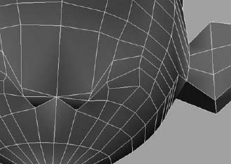
Mirroring usually causes the mouth vertices to pinch.
3. Once the mirroring is complete, check your normals to verify their position [Display > Polygons > Face Normals].
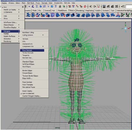
Checking the position of the Face Normals.
4. If any are flipped inward, you will need to change their direction by selecting the geometry and first going to [Normals > Conform]. This usually solves the problem, however you may have to reverse them all if they now ALL face inward. If so, then [Normals > Reverse] will correct their direction. To hide the normals again, go to : [Display > Polygons > Face Normals].
5. Once you have all of the normals facing outward, you can select the entire object in object mode and go to [Normals > Average Normals] to make the geometry appear smoother without adding more physical geometry.
6. Delete history on body_geo [Edit > Delete by Type > History].
7. Save your scene file.
a. Go to [File > Save as].
b. Name your scene 02_asgn09_03_convert_to_polys_geo.ma.
As mentioned earlier in the chapter, a NURBS character is quick and easy with the approach covered Assignments 2.1–2.8. However, if you would like to create a seamless character or have better control over texturing, you will need to convert your character into polygonal surfaces.
Remember, the first time you model your character, you may not end up with the desired look. Do not be afraid to scrap the areas that are not working and start again.
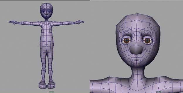
In this character, I remodeled the head all over again in polygons.