
You have many uses for text in your drawings, including titles of views, notes, and dimensions. It's not uncommon for the majority of a page to be covered with text outlining pertinent information, including legal and code requirements, construction or manufacturing information, and contact information for companies or individuals involved in the project. Each of these might require a different height, orientation, justification, and style of lettering. To control text, you'll need to learn how to do the following:
AutoCAD offers two types of text objects: single-line and multiline. Single-line text makes a distinct object of each line of text, whether the line is one letter or many words. This type of text is useful for titles of drawings, titles of views within a drawing, room labels, and schedules. You use multiline text for dimensions, tables, and longer notes. With multiline text, AutoCAD treats a whole body of multiline text as one object, whether the text consists of one letter or many paragraphs.
The two types of text share the same text styles, but each has its own command for placing text in the drawing. When you modify text, you can use the same commands for either type of text, but the commands operate differently for multiline text than for single-line text. AutoCAD handles any text used in dimensioning—a process by which you indicate the sizes of various components in your drawing—differently from other text; I'll cover dimensioning in Chapter 12, "Dimensioning a Drawing."
You'll progress through this chapter by first looking at the process of setting up text styles. You'll then start placing and modifying single-line text in the cabin drawing. Finally, you'll look at the methods for creating and controlling multiline text as it's used for notes and tables. If you work in a non-AEC profession or trade, be assured that the features presented in this chapter will apply directly to your work. The basic principles of working with text in AutoCAD and LT "cross the curriculum" (an educational metaphor) and apply universally.
In AutoCAD, a text style consists of a combination of a style name, a text font, a height, a width factor, an oblique angle, and a few other mostly static settings. You specify these text style properties with the help of a dialog box that opens when you start the Style command. You'll begin by setting up two text styles—one for labeling the rooms in the floor plan and the other for putting titles on the two views. You'll need a new layer for text:
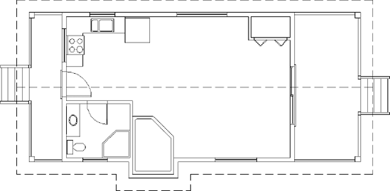
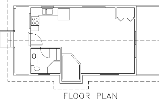
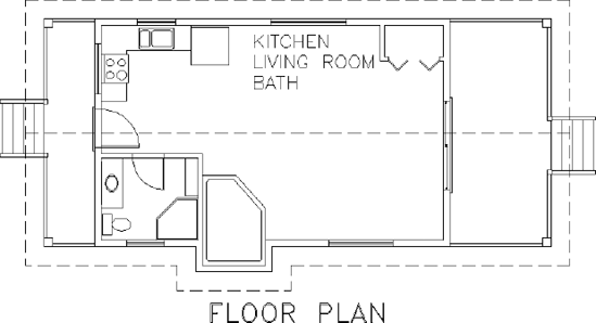
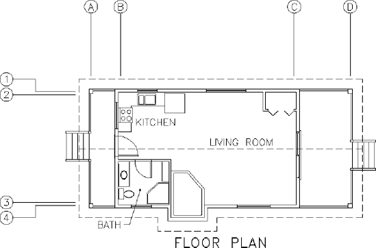
Your drawing should look like Figure 8.1.
When you set up text styles for a drawing, you have to determine the height of the text letters. To make this determination, you first need to decide the scale at which the final drawing will be printed.
In traditional drafting, you can ignore the drawing scale and set the actual height of each kind of text. This is possible because, although the drawing is to a scale, the text doesn't have to conform to that scale and is drawn full size.
In AutoCAD, a feature called layouts makes it possible to set the height of text in the same way—that is, at the height at which it will be printed. You'll learn about using layouts in Chapter 14, "Using Layouts to Set Up a Print." In that chapter, you'll place text on layouts; in this chapter, I'll demonstrate how you use text without layouts. You'll place text in the cabin drawing. The drawing is actual size, but the text has to be much larger than actual size because both the drawing and its text will be scaled down by the same factor in the process of printing the drawing.
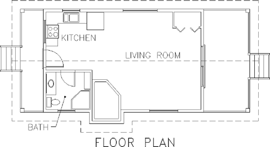
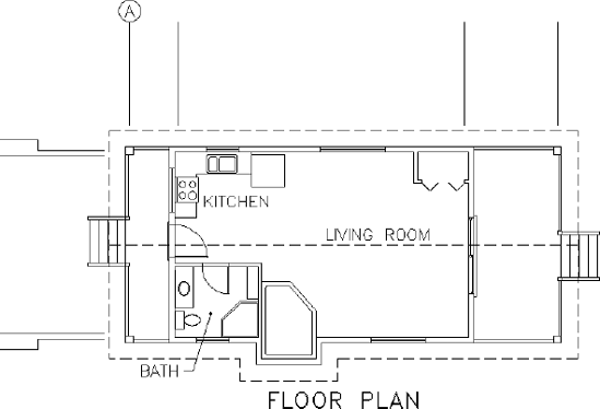
In this drawing, you'll use a final scale of 3/16″ = 1′−0″ (1 = 70). This scale has a true ratio of 1:64 (1:70) and a scale factor of 64 (see Table 8.1). If you want text to be 3/16″ (4.5 mm) high when you print the drawing at 3/16″ (1:70) scale, multiply 3/16″ (4.5 mm) by the scale factor of 64 (70) to get 12″ (310 mm) for the text height. You calculate the scale factor by inverting the scale fraction and multiplying it by 12 (310). You can check that calculated text height by studying the floor plan for a moment and noting the sizes of the building components represented in the drawing. The stair tread depth is 10″, and the text will be slightly larger.
Table 8.1. Standard Scales and Their Corresponding Ratios
Scale True | Scale Factor |
|---|---|
1″ = 1′−0″ | 12 |
1/2″ = 1′−0″ | 24 |
1/4″ = 1′−0″ | 48 |
3/16″ = 1′−0″ | 64 |
1/8″ = 1′−0″ | 96 |
1/16″ = 1′−0″ | 192 |
Similarly, when using decimal units, the scale factor is derived by dividing the second number in the ratio by the first such as: 1:50 has a scale factor of 50 and 1:60 has a scale factor of 60.
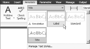
Now that you have a good idea of the required text height, it's time to define a new text style. Each new AutoCAD .dwg file comes with two predefined text styles: Standard and Annotative. You'll add two more. Follow these steps:
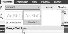
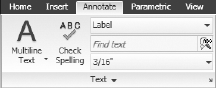
Expand the Text Style drop-down list in the Text panel, and choose Manage Text Style (see Figure 8.2) or enter st

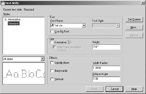
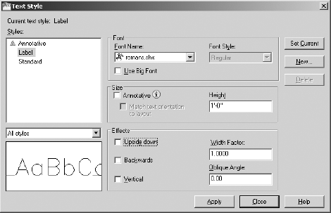
The Text Style dialog box opens (see Figure 8.3). In the Styles area, you'll see the default Standard text style as well as the Annotative text style.
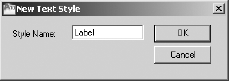
Click New to open the New Text Style dialog box. You'll see a highlighted Style Name text box set to style1 in it. When you enter a new style name, it will replace style1.
Enter Label
Move down to the Font area, and click the Font Name drop-down list to open it. A list of fonts appears; the number of choices depends on what software is installed on your computer. AutoCAD can use both its native
.shx(Compiled Shape) font files and Windows.ttf(TrueType font) files.Scroll through the list until you find
romans.shx, and then click it. The list closes, and in the Font Name text box theromans.shxfont replaces thetxt.shxfont that was previously there. In the Preview area in the lower-left corner, a sample of theromans.shxfont replaces that of thetxt.shxfont.Press the Tab key a few times to move to the next text box. The Height setting is highlighted at the default of 0′−0″ (0).
Enter 12 (305), and then press Tab again. A height of 1′−0″ (305 mm) replaces the default height. Your Text Style dialog box should look like Figure 8.5.
You won't need to change any of the other parameters that define the new text style. They can all stay at their default settings.
Click the Apply button at the bottom of the dialog box. The Label text style is saved with the current drawing and becomes the current text style. The current text style appears in the Text Style drop-down list in the Text panel, as shown in Figure 8.6.
Note
The current text style is similar to the current layer. All text created while a text style is current will follow the parameters or settings of that text style.
When you define a new text style, you first name the new style. This has the effect of making a copy of the current text style settings, giving them the new name and making the new text style current. You then change the settings for this new style and save the changes by clicking Apply.
Before you close the dialog box, define another text style:
Click the New button again.
In the New Text Style dialog box, enter Title, and click OK. A new text style called Title is created and is now the current text style. Its font, height, and other settings are a copy of the Label text style. Now you'll make changes to these settings to define the Title text style.
Click the current font,
romans.shx. The drop-down list of fonts opens. Scroll up one font and clickromand.shx. The list closes, andromand.shxappears as the chosen font.Press Tab until the Height text box is highlighted, enter 18 (457), and then press Tab again. This changes the height parameter to 1′−6″ (457 mm).
Tip
If you press
Click Apply, and then click Close.
Of the many fonts available in AutoCAD, you'll use only a few for your drawings. Some are set up for foreign languages or mapping symbols. Others would appear out of place on architectural or technical drawings but might be just right for an advertising brochure or a flier. Later in this chapter, you'll have a chance to experiment with the available fonts.
Refer to Figure 8.3 for a moment, and note that the Standard text style has a height of 0′−0″ (0). When the current text style has a height set to 0, you're prompted to enter a height each time you begin to place single-line text in the drawing. The default height will be 3/16″ (or 0.20 for decimal units and 2.5 for metric). Multiline text will use the default height of 3/16″ unless you change it.
Now that you have two new text styles, you can start working with single-line text.
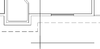
Your first task is to put titles in for the floor plan using the new Title text style.
The titles need to be centered approximately under each view. If you establish a vertical guideline through the middle of the drawing, you can use it to position the text. Guidelines aren't as elegant a solution as a temporary track point, but they are quick and don't require too much forethought. Here are the steps:
Pan the drawing up to create a little more room under the floor plan.
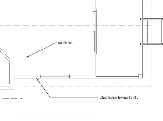
Set up your osnaps and status bar options so that Polar Tracking and Object Snap are on and the Endpoint and Midpoint osnaps are running. Drop a line from the midpoint of the ridgeline in the floor plan straight down to a point near the bottom of the screen.
Offset the horizontal, outside wall line, to the right of the pop-out in the floor plan down 6′ (1830 mm), as shown in Figure 8.7.

The bottom line of text in the Command window says
Specify start point of text or [Justify/Style]:. The line above it displays the name of the current text style and the style's height setting. The bottom line is the actual prompt, with three options. By default, the justification point is set to the lower-left corner of the text. You need to change it to the middle of the text to be able to center it on the guideline.Enter j
Enter c
Use the Shift+right-click menu to choose the Intersection osnap, and pick the intersection of the guideline and the offset line.
For the rotation, press
With Caps Lock on, enter FLOOR PLAN
Press
Erase the offset line and the vertical guideline. Your drawing will look like Figure 8.11.
You specified a location for the text in two steps: first, you set the justification point of each line of text to be centered horizontally; second, you used the Intersection osnap to position the justification point at the intersection of the two guidelines. I'll discuss justification in more depth a little later in this chapter.
Next you'll move to the interior of the cabin floor plan and place the room labels in their respective rooms.
Text for the room labels will use the Label text style, so you need to make that style current before you start placing text. You can accomplish this in the Text panel:
Click the Polar Tracking, Ortho Mode, and Object Snap buttons on the status bar to turn off these features.
Expand the Text Style drop-down list on the Text panel to display a list of all the text styles in the drawing. Click Label, as shown in Figure 8.12, to make Label the current style.
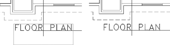
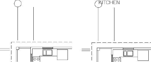
Start the Dtext command, and notice that the FLOOR PLAN text shows as dashed lines. If you press
Pick a point in the living room between the refrigerator and the closet.
Press
With Caps Lock on, enter KITCHEN
For this text, you used the default Left justification and each line of text was positioned directly below the previous line at a spacing set by AutoCAD. In many cases, it's more efficient to enter a list of words or phrases first and then move the text to its appropriate location. That's what you're doing for this text. When you know the location of the insertion point for the next line, you can click that point, instead of pressing
You'll eyeball the final position of this text because it doesn't have to be exactly centered or lined up precisely with anything. It should just sit in the rooms in such a way that it's easily readable:
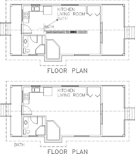
Click the BATH text. One grip appears at the justification point of the text.
Click the grip to activate it. The BATH text is attached to the cursor and moves with it (see the top of Figure 8.14). The Stretch command automatically starts. Because text can't be stretched, the Stretch command functions like the Move command.
Move the cursor below and outside the bathroom and just beyond the eave line, and then click to place text at its new location.
Press Esc to deselect the text and remove the grip (see the bottom of Figure 8.14). Then select the KITCHEN text.
Click the grip for the newly selected text.
Pick a point in the kitchen so that the KITCHEN text is positioned approximately at the center of the room. Press Esc to deselect the text.
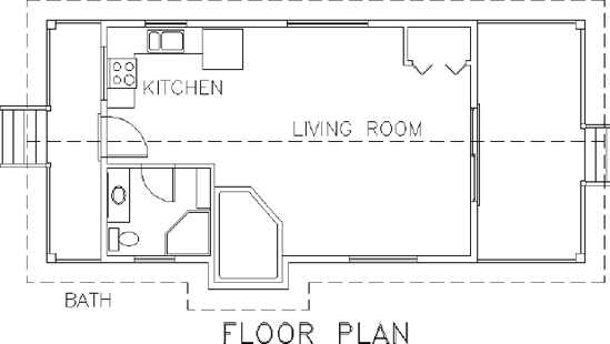
Repeat this process to move the LIVING ROOM text to an appropriate location without crossing the roof line (see Figure 8.15).
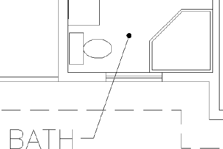
A leader is a short series of lines that run from a note or symbol to a corresponding feature in your drawing. Although leaders are normally associated with dimensions (covered in Chapter 12), you can also use them with plain text. The leaders that you draw manually will not, however, have the adaptability of actual dimension leaders, but are just simple geometry used to link two features in a drawing. In this situation, you want to associate the BATH text with the bathroom by drawing a polyline from the text to the room.

Draw a short horizontal segment from the right of the text approximately 8″ (200 mm) long, extending even further to the right.
Toggle Ortho Mode off again, click a second point inside the bathroom, and press
To terminate the polyline inside the bathroom, you'll place a donut at the endpoint. A donut is actually a closed, circular polyline with a width assigned to it. The width is determined by defining the outside diameter and inside diameter of the donut ring. When the inside diameter is set to zero, a closed, filled circle is created.

At the
Specify inside diameter of donut:prompt, enter 0At the
Specify outside diameter of donut:prompt, enter 3Turn on the running osnaps and, at the
Specify center of donut or:prompt, click the endpoint of the polyline inside the bathroom. Your bathroom, BATH text, and leader should look like Figure 8.17.Press
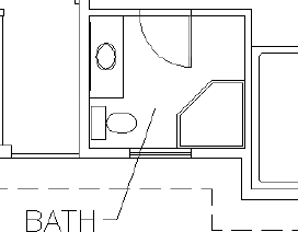
As you've seen, you can easily move text around the drawing using the grip at the insertion point. Often, however, you'll be unable to position it in the optimum location without the drawing looking crowded or sloppy. A leader can tie text to a specific feature adding readability to your drawing. Occasionally, the location of a line and text coincide and the conditions do not allow you to relocate the text. We are going to force a situation here where you'll need to erase parts of these lines around the text. To do this, you'll use the Break command and then, at the end of the exercise, revert the drawing back to its original configuration. If you do not want to complete the next section, save your drawing as Cabin08b.dwg and skip to the "Using Text in a Grid" section.
The Break command chops a line into two lines. When you're working with text that intersects a line, you'll usually want a gap between the lines after the break. The Break command provides this option as well as others. Follow these steps:
Enter undo
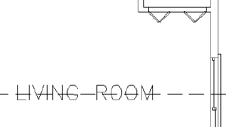
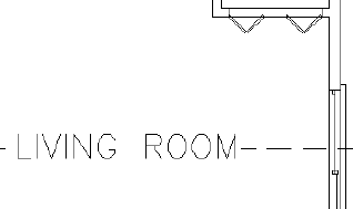
Select the LIVING ROOM text and move it so that it rests on the ridgeline, as shown in Figure 8.18.

Place the pickbox on the ridgeline just to the right of the text and click. The line ghosts, and the cursor changes to the crosshair cursor. You just selected the line to break and picked one of the break points.
Put the crosshair cursor on the roofline just to the left of the text, and pick that point. The line is broken around the text, and the Break command ends. As you can see in Figure 8.19, the text is easier to read now than it was when the line was running through it.
You don't want to retain your drawing in its current state, so enter undo
Your drawing should look like Figure 8.20. Save your drawing as
Cabin08b.dwg.
Tip
The multiline text objects have a mask feature that creates an envelope over and around the text, hiding the objects behind it. Unlike the breaking-lines approach, the masked objects reappear when you move the text. Masking is not supported for single-line text, but the Text Mask utility is available in the Express Tools. Express Tools are not included with AutoCAD LT.
A Closer Look at the Break Command
Use your own judgment to determine how far from the text a line must be broken back. You have to strike a balance between making the text easy to read and keeping what the broken line represents clear. For the bathroom, I directed you to keep the text completely out of the room because, if any lines of the fixtures had to be broken to accommodate the text, it might have made it difficult for a viewer to recognize that those lines represent a shower, sink, or a toilet.
Here are some other options for the Break command:
Ordinarily, when you select a line to be broken, the point where you pick the line becomes the beginning of the break. If the point where the break needs to start is at the intersection of two lines, you must select the line to be broken somewhere other than at a break point. Otherwise, AutoCAD won't know which line you want to break. In that case, after selecting the line to break, enter f
To break a line into two segments without leaving a gap, click the Break At Point button, which is on the expanded Modify panel. You might want to do this to place one part of a line on a different layer from the rest of the line. To break the line this way, start the command, select the line to break, and then pick the point on the line where the break is to occur, using an osnap if necessary. AutoCAD makes the break and ends the command.
AutoCAD provides a grid of dots or lines, which you worked with in Chapter 3. The grid is a tool for visualizing the size of the drawing area and for drawing lines whose geometry conforms to the spacing of the dots or lines. Many floor plans have a separate structural grid, created specifically for the project and made up of lines running vertically and horizontally through key structural components of the building. At one end of each grid line, a circle or a hexagon is placed and a letter or number is centered in the shape to identify it. This kind of grid is usually reserved for large, complex drawings, but you'll put a small grid on the cabin floor plan to learn the basic method for laying one out:
Create a new layer called Grid. Assign it a unique color, and make it current.
Offset the roofline polyline 10′ (3050 mm); then pan and zoom as necessary so that the cabin is centered on screen and takes up only about 75 percent of the drawing area.
Turn Object Snap on if it's off; set the Endpoint, Midpoint, and Perpendicular osnaps to be running; and then start the Line command.
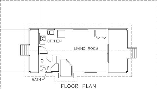
Draw lines from the upper-left and upper-right inside corners of the walls up to the offset roof line. Then draw lines from the left upper and lower inside corners of the exterior walls to the vertical offset line on the left (see Figure 8.21).
The grid lines need to be centered on the structural member they are identifying, in this case an 8×8 (204×204) column. Start the offset command, enter e
Offset each of the grid lines 4″ (102 mm) toward the inside of the cabin. You may notice that the toilet will interfere with the new column in the lower-left corner of the cabin. Move the toilet up 4″ (102 mm) to add clearance and then adjust the size of the sink counter and mirror as well.
Now you need to draw grid lines for the posts at the corners of the decks. Draw lines from the horizontal midpoint of the top-right and top-left deck posts vertically to the offset roofline.
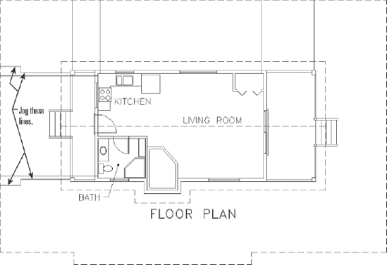
Next, draw lines from the upper-left and lower-left deck posts horizontally to the offset roof line. This time add a jog to each column line so that their endpoints are not too close to the endpoints of the existing horizontal column lines (see Figure 8.22). You need to leave space for the column tag and don't want them to overlap.
Tip
Use the F8 key to toggle Ortho mode on and off to keep the jogged lines straight.
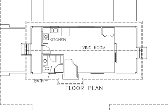
The column lines should not extend all the way to the cabin; there should be a gap to keep the drawing from getting congested and confusing. Offset the original roofline, without erasing the original, 6″ (150 mm) to the outside and then trim all eight column lines back to this new Polyline, as shown in Figure 8.23. You may need to zoom in to the end of each line being trimmed to ensure that the correct object is selected for trimming.
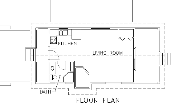
Erase the offset rooflines you created in steps 4 and 9, and then zoom out to a view that includes the floor plan and the grid lines (see Figure 8.24).
This completes the grid lines. To finish the grid, you need to add a circle with a letter or a number in it to the left or upper end of the lines. You'll use letters across the top and numbers running down the side:

At the
Specify first end point of circle's diameter:prompt, pick the upper end of the leftmost vertical grid line.Make sure Dynamic Input is on. Then move the cursor directly above the last point and enter 2′ (610) or enter 2′<90
Click the KITCHEN text. A grip appears.
Click the grip; type c, for copy; and press
Activate the Center osnap, and click the circle on the grid. The KITCHEN text appears on the circle, with the lower-left corner of the text at the center of the circle (see the right image of Figure 8.25). Press Esc twice, once to end the Stretch function and again to clear the grip.
Click the copy of the KITCHEN text that is now on the grid, right-click to bring up the context menu, and then click Properties to open the Properties palette. Text appears on the drop-down list at the top, telling you that you've selected a text object.
Use the Properties palette to make the following changes to the KITCHEN text:
This might seem like a roundabout way to generate letters for the grid symbols, but this exercise is meant to show you how easy it is to use text from one part of the drawing for a completely different text purpose. It's a handy technique, as long as you want to use a font that has been chosen for a previously defined text style. A faster way to do this is to use the Single Line Text command with the Justify setting set to Middle, use the Center osnap to place the text cursor at the center of the circle, and then enter A
Change Layer, in the General rollout, from Text1 to Grid.
Change Contents, in the Text rollout, from KITCHEN to A.
Change the Justify setting from Left to Middle.
For each change, follow these steps in the Properties palette:
Click the category in the left column that needs to change. If the setting is on a drop-down list, an arrow appears in the right column.
Click the down arrow to open the list. In the case of the KITCHEN text, just highlight it because there is no drop-down list.
Click the new setting or enter it.
When you've finished, close the Properties palette and press Esc to deselect the text.
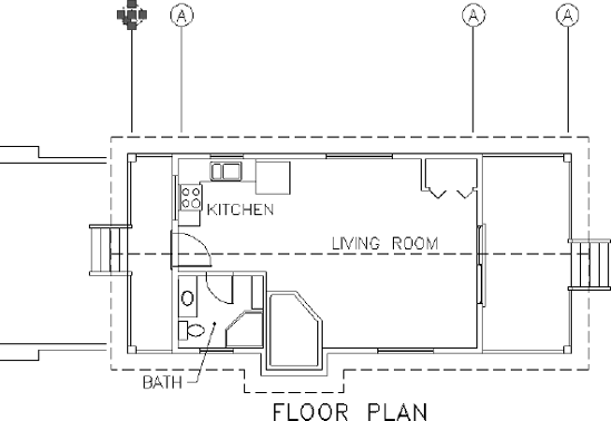
The KITCHEN text changes to the letter A, is centered in the grid circle, and moves to the Grid layer (see Figure 8.26).
You used the Center osnap on the KITCHEN text to position its justification point at the center of the circle. You then modified the justification point from the Left position (which is short for Base Left) to the Middle position (short for Middle Center). The Middle position is the middle of the line of text, horizontally and vertically. So what you did had the effect of centering the text in the circle. You'll now look at text justification briefly.
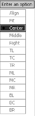
Each line of single-line text is an object. It has a justification point, which is similar to the insertion points on blocks. When drawing, you can use the Insert osnap to locate the justification point of text precisely (or the insertion point of blocks) and thereby control the text's position on the drawing. When you use the Single Line Text or Dtext command, the default justification point is the lower-left corner of the line of text. At the Dtext prompt (Specify start point of text or [Justify/Style]:), if you enter j
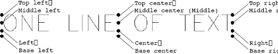
Figure 8.27 shows most of these options. The dots are in three columns—left, center, and right—and in four rows—top, middle, lower, and base. The names of the justification locations are based on these columns and rows. For example, you have TL for Top Left, MR for Middle Right, and so on. The third row down doesn't use the name Lower; it simply goes by Left, Center, and Right. Left is the default justification position, so it's not in the list of options. The Middle position sometimes coincides with the Middle Center position, but not always. For example, if a line of text has descenders—portions of lowercase letters that drop below the baseline, such as j and p—the Middle position drops below the Middle Center position. Finally, the lowest row, the Base row, sits just below the letters at the lowest point of any descenders.
To finish the grid, you need to copy the grid circle with its text to each grid line and then change the text:
Be sure the Endpoint osnap is still running. Then, at the command prompt, select the letter A and the circle. Grips appear: two for the text, one at the original justification point and one at the new justification point; one at the center of the circle; and one at each of the circle's quadrant points.
Click the grip at the bottom of the circle to activate it.
Right-click, and choose Move from the context menu; right-click again, and choose Copy to activate the copy option.
Pick the top end of each vertical grid line; then right-click and choose Enter to terminate the command (see Figure 8.28).
Move back to the original grid circle and select the grip on the right side of the circle to activate it.
Repeat steps 3 and 4 to copy the original grid circle and letter to the left end of each horizontal grid line.
Press Esc to deselect the objects and remove the grips. Then, if necessary, use the Stretch command to adjust the jogged lines and eliminate any overlap.
Now you'll use the Ddedit command to change the text in each circle.
Be sure Caps Lock is on, and then double-click the letter A in the second grid circle from the left on the top row. The text now has a blue background to indicate that it is being edited.
Enter B
Tip
Editing text is one of the situations where pressing the spacebar does not have the same effect as pressing
Click the A in the next circle to the right, and then enter C
Repeat this process for the remaining five grid circle letters, changing them to D, 1, 2, 3, and 4. Press
Save this drawing as
Cabin08c.dwg.
Often, it's easier to copy existing text and modify it than to create new text, and grips are a handy way to copy text. Using the Edit Text command (technically called Ddedit) is a quick way to modify the wording of short lines of text, meaning those that consist of a word or a few letters. The Properties palette is useful for changing all aspects of a line of text.
For the next exercise with text, you'll get a chance to set up some more new text styles, place text precisely, and use the Ddedit command again to modify text content. You'll do all this while you develop a title block for your drawing.
The first step in creating a title block and border for the cabin drawing is deciding on a sheet size for printing the final drawing. Because many people have access to 8.5″×11″ (210×297) format printers, you'll use that sheet size. So if you print the drawing at a scale of 3/16″ = 1′−0″ (1 = 60), will it fit on the sheet?
To answer that question, you have to ask how big an area will fit on an 8.5″×11″ (210 mm×297 mm) sheet at 3/16″ = 1′−0″ (1:60) scale? The answer is quite simple: if every inch (millimeter) on the sheet represents 64″ (60 mm) in the drawing (12″ / (3/16″)) (60/1), you multiply each dimension of the sheet in inches (millimeters) by 64″ (60) per inch. For this sheet, you multiply 8.5″×64″ (210 mm×60) per inch to get 544″ (12,600 mm) or 45′−4″. You multiply 11″×64″ (297 mm×60) per inch to get 704″ (17,820 mm) or 58′−8″. So, the 8.5″×11″ (210 mm×297 mm) sheet represents a rectangle with dimensions of approximately 45′×58′ (12,600 mm×17,820 mm) at a scale of 3/16″ = 1′−0″ (1:60) (usually called three-sixteenths inch scale). You won't be able to show the entire column lines at this scale but, when I discuss layouts in Chapter 14, you will learn how to display the content of a single drawing at different scales. Even when you account for the unprintable area around the perimeter of the sheet, there should be plenty of room for your cabin drawing. This is the information you need to start creating the title block.
The border of the drawing will be set in from the edge of the sheet. Here are the steps:
Create a new layer called Tblk1. Leave the default color assigned, and make this layer current.
Start the Rectangle command (used in Chapter 4 to make the doors).
At the prompt, enter 0,0
This draws a rectangle that may extend off the top of the screen.
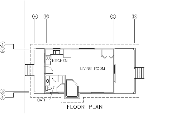
Use Zoom Extents to zoom out until the entire rectangle is visible in the drawing area (see Figure 8.30).
You need to fit the drawing into the rectangle as if you were fitting it on a sheet of paper. The easiest and safest way to do this is to move the rectangle over to enclose the drawing. You'll leave plenty of room for the elevations that you will draw in a later chapter.
At the command prompt, click the rectangle to select it. Grips appear at the corners of the rectangle.
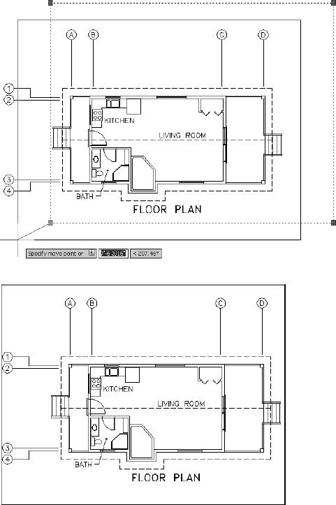
Click the lower-left grip. Press the spacebar once to switch from Stretch mode to Move mode. Then move the rectangle over the drawing (see the top of Figure 8.31).
When the rectangle is approximately in the position shown in the bottom of Figure 8.31, click. Press Esc to deselect the rectangle. The rectangle is positioned around the drawing and represents the edge of the sheet.
You need a border set in from the edge. Offset the rectangle 2′ (600 mm) to the inside. With a scale of 3/16″ = 1′−0″ (1 = 60), each 1′−0″ (60 mm) on the drawing will be represented by 3/16″ (1 mm) on the sheet. So a 2′ (600 mm) offset distance will create an offset of 3/8″ (10 mm) on the printed sheet.
Double-click the inside rectangle to start the Pedit command.
Enter w
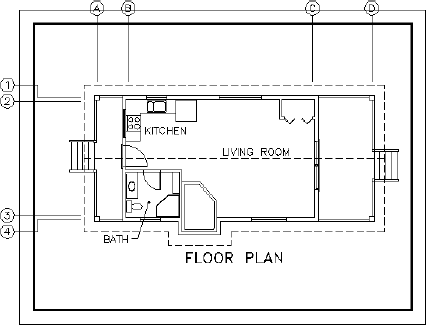
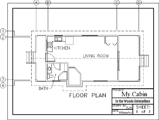
Move both rectangles to center the cabin. Use Zoom Extents, and then zoom out a little to create a view in which the drawing with its border nearly fills the screen (see Figure 8.32). The outer rectangle represents the edge of the sheet of paper, and the thicker, inner rectangle is the drawing's border.
The title block is a box that contains general information about a drawing, such as the name of the project, the design company, and the date of the drawing. It will be set up in the lower-right corner of the border and will use the same special line, the polyline, which is created when the Rectangle command is executed.
You first used the Rectangle command in Chapter 4 for drawing the doors. At that time, I mentioned that rectangles created with the Rectangle command consist of a polyline whose four segments are grouped as one object. In step 10 of the previous section, you saw that these segments could have varying widths.
The Polyline command, nicknamed the Pline command, allows you to draw continuous straight and curved line segments of varying widths, with all segments behaving as if they were one object.
When you explode a polyline using the Explode command, the segments lose any width they have and become independent lines. The ability of a polyline to have a width makes it useful in constructing title blocks. You'll use the Pline command to draw the various lines that make up the title block, and then you'll fill in the text:
Zoom in to a view of the lower third of your drawing, including the bottom of the border. Be sure the Endpoint and Perpendicular osnaps are running.

Click the Polar Tracking button on the status bar to turn on polar tracking. Hold the cursor over the lower-left corner of the inner border, and when the vertical tracking point appears, move the cursor directly above that point and enter 10′
Notice the bottom two lines of text in the Command window. The upper one tells you the width set for the polyline, currently 0′−0″ (0). The lower one says
Specify next point or [Arc/Halfwidth/Length/Undo/Width]:, listing the options for the Polyline command with the default option being to pick a second point. This is the time to set the line width.Enter w
Hold the crosshair cursor on the right side of the border. When the Perpendicular osnap marker appears on the border line, click. Then press
Restart the Polyline command. Pause the cursor over the bottom-right corner of the border to set the temporary track point, move it directly to the left, and enter 16′
Move the cursor to the last polyline that you drew and, when the Perpendicular osnap marker appears, click. The left edge of the title block is drawn (see the top of Figure 8.34). Press
Trim the left half of the upper horizontal pline drawn back to the pline just drawn.
Offset the horizontal pline down 3′−6″ (1065 mm), offset this new line down 2′−6″ (762 mm), and then offset this new line down 2′ (610 mm). (See the middle of Figure 8.34.)
Start the Pline command. Using Midpoint osnap, start a pline at the midpoint of the third horizontal line down. Then end the segment at the bottom of the border, taking advantage of the running Perpendicular osnap. Press
Trim the right side of the line just above the bottom of the border, back to the line you just drew (see the bottom of Figure 8.34).
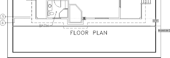
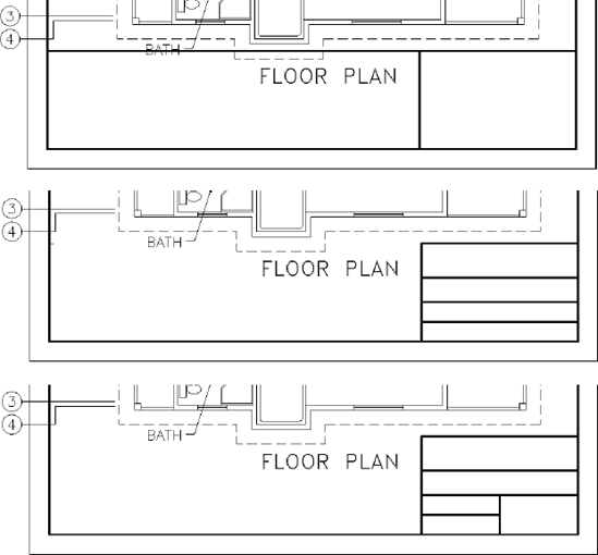
Figure 8.34. Building the title block: the left edge (top), the horizontal lines (middle), and the last line trimmed (bottom)
The lines for the title block are almost done. Some of the plines might look wider than others. The monitor distorting the picture at the current view almost certainly causes this. By zooming in, you can assure yourself that everything is correct.
Zoom in to a close view of the title block. Notice that the intersection of the outer lines in the upper-left corner doesn't seem clean.
Zoom in to that corner using a zoom window (see the top of Figure 8.35). The lines don't intersect in a clean corner because they are two separate polylines. You need to join them as one.

Click Join or enter j
Use Zoom Previous and then use Zoom with the scroll wheel to zoom out enough to see the entire title block (see Figure 8.36).

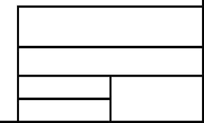
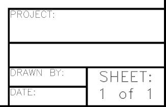
The title block has five boxes that will each contain distinct pieces of information. The large one at the top will contain the name of the project. Below that will be the name of the company producing the drawing—your company. (If you don't have a company name, make one up.) Below that on the left will be the initials of the person (you) who drew this drawing, and below that will be the date. In the lower-right corner will be the sheet number, in case more than one sheet is required for this project. This follows a standard format. Most title block layouts contain this information and more, depending on the complexity of the job.
You need to put labels in some of the boxes to identify what information will appear there. For this, you need to set up a new text style.
Expand the Text Style drop-down list, on the Text panel under the Ribbon's Annotate tab, and click Manage Text Styles.
The Label text style should still be current. If not, then select it. Click New, enter Tblk-label, and then click OK. Leave the font set to
romans.shx, but change the height to 8″ (204). Click Apply and then Close. Tblk-label is the current text style.
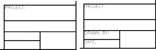
Press
If necessary, move this text to the upper-left corner, as far as possible, while still allowing it to be readable. It will help if Polar Tracking and Object Snap are temporarily turned off.
Tip
If you have running osnaps and need to have them off for one pick, you can click the Snap to None osnap button. Doing so cancels all running osnaps for the next pick. If you need running osnaps turned off for several picks, click the Object Snap button on the status bar. Click it again when you want the running osnaps to become active.
Use the Copy command to copy this text to the bottom two boxes on the left, using the endpoint of the horizontal lines above each of the boxes as the base and displacement points. This keeps each piece of text in the same position relative to the upper-left corner of each box.
Double-click the upper of the two copies of text to start the Ddedit command.
Enter DRAWN BY: and press
Enter DATE: and press
Using the Ddedit command is a quick way to change the wording of text and to correct spelling. You have to change one line at a time, but the command keeps running until you stop it. You can also change the Contents text box in the Properties palette.
The next area to work on is the lower-right box. This is where the sheet number appears, and it's usually displayed in such a way that the person reading the drawing can tell not only the page number of the current sheet but also the number of sheets being used for the project. You'll create a new text style for this box:
Open the Text Style dialog box and click New.
Turn off Caps Lock, then enter Sheet_No and click OK. For the font, select
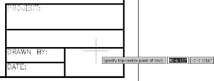
romand.shx. Change the height to 1′−1″ (330). Click Apply, and then click Close. Sheet_No is now the current text style.Start the Dtext command, and enter j
Press
With polar tracking on, use the Move command to move the text down and center it vertically in the box (see Figure 8.39). Remember, when you select the text to move it, you have to pick each line because they are two separate objects.
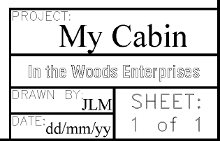
Now it's time for you to experiment. Use the techniques you just learned to fill in the text for the other four boxes. Feel free to try other fonts, but you'll have to adjust the height for each text style so that the text fits in its box. Some guidelines for height follow:
Tip
When the Font Name input box is highlighted, use the up and down arrows on the keyboard to scroll through the fonts and watch the preview window to see what the font looks like.
Box | Recommended Height of Text |
|---|---|
Project | 1′−8″ (510 mm) |
Company | 1′−0″ (305 mm) |
Drawn By | 0′−10″ (254 mm) |
Date | 0′−10″ (254 mm) |
You can use the same style for all text with the same properties, but you'll have to set up a new style for each new font or height you choose unless you set up a style with a height of 0′−0″ (0). In that case, you'll be prompted for the height each time you start to place text in the drawing. This is the recommended way to operate for the top two boxes because it will give consistency to the text even when heights vary. You might try several fonts and then come back to this technique at the end. I also recommend you use a relatively simple font for the text in the Drawn By and Date boxes.
Try these fonts:
romant.shxorromanc.shxAny of the swis721 series
Times New Roman
Technic
SansSerif
CityBlueprint or CountryBlueprint
Arial
In the top two boxes, you can center the text vertically and horizontally if you draw a line diagonally across the box, choose Middle Center as a justification for the text, and use the Midpoint osnap to snap to the diagonal line when you start the text. For the Drawn By and Date boxes, centering the text horizontally isn't advisable because the label text already in the boxes takes up too much space. However, you can use the diagonal line to center it and then move the text to the right until it makes a good fit. Using polar tracking will keep the new text vertically centered.
Be careful in your use of running osnaps as you position text. If you're eyeballing the final location, it's best to have no running osnaps. On the other hand, if you're precisely locating justification points by snapping to lines and other objects, you might try having the following osnaps running: Endpoint, Intersection, Perpendicular, and Insertion, with Midpoint optional. When you finish, your title block should look something like Figure 8.40.
If you're going to design your own company title block, be ready to spend a little time setting it up and deciding which fonts will give the look that best reflects the image you want to project. You can then use this title block on all your subsequent projects.
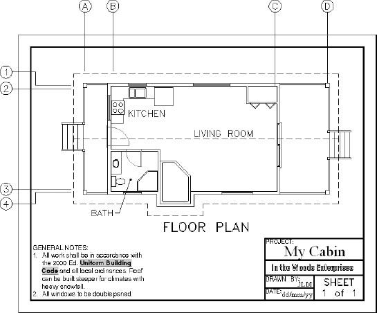
Use Zoom to Extents, and then zoom out a little to view the entire drawing. Save this drawing (see Figure 8.41) as Cabin80d.dwg.
Now that you've created a title block and a border, you'll briefly look at the title blocks and borders that AutoCAD provides in its template files and see how you can use these files to set up a new drawing. Follow these steps:
Click the New icon on the Quick Access toolbar to open the Select Template dialog box.
Double-click
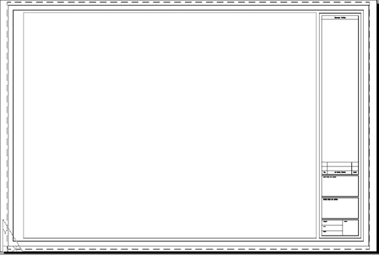
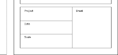
Tutorial-iArch.dwtorTutorial-mArch.dwtfor an imperial or metric template. The new drawing appears with a title block and border (see Figure 8.42). In addition, this sheet has extra lines and area along the right edge for listing revisions to the drawing and company information.Zoom in to the title block on the lower part of the drawing, as shown in Figure 8.43. Notice that it has spaces for the scale and sheet number, among other information, and that some areas are left blank.
Close this drawing, and click the New button again to look at some of the other template files on the list. Don't worry about the part of the template name that identifies plot style types. I'll cover this in Chapter 15, "Printing an AutoCAD Drawing." The background for the template files is gray because they use layouts, which I'll introduce in Chapter 14, "Using Layouts to Set Up a Print."
When you open a new drawing by selecting a template file, AutoCAD uses the template file as the basis of your new drawing. It copies the information in the template file onto the new drawing file and names the new drawing Drawing1, Drawing2, and so on. You can convert any drawing into a template file. Simply choose Save As
The final section of this chapter introduces you to multiline text, which you'll also work with as you learn about dimensions in the next chapter, and it introduces you to AutoCAD's spelling checker.
Multiline text (often referred to as Mtext) is more complex than single-line text. You can use it in the same way you used single-line text in this chapter, but it can do more. When you have several lines of text or when you need certain words within a line of text to appear differently than the adjacent words, multiline text is the best feature to use.
A paragraph of multiline text is a single entity. The text wraps around, and you can easily modify the length of a line after you place the text in the drawing. Within the multiline text entity, all text can be edited and behaves as if it were in a word processor. You can give a special word or letter of the text its own text style or color. Everything you learned about defining a new text style applies to multiline text, because both kinds of text use the same text styles. Just as polylines become lines when exploded, multiline text is reduced to single-line text when exploded.
Dimensions use multiline text, and any text that is imported into an AutoCAD drawing from a word processing document or text editor becomes multiline text in the drawing. In this section, you'll learn how to place a paragraph of multiline text in the cabin drawing and then modify it. In Chapter 12, you'll work with dimension text and text with leader lines, both of which use multiline text.
Tip
If you are using AutoCAD and have the Express Tools installed, the Txt2mtxt command (on the menu bar, click Express
You'll start by adding a note in the lower-left corner of the Cabin08d drawing, using the Multiline Text command:


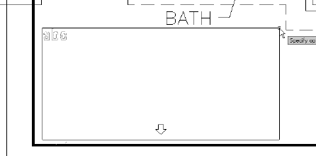
Select a point near the left border line in line with the top of the title block. The prompt now says
Specify opposite corner or [Height/Justify/Line spacing/Rotation/Style/Width/Columns]:. These are all the options for the Multiline Text command.If the current style is Label, go on to step 5. Otherwise, expand the Text Style drop-down list and choose Label.
Unlike single-line text, Mtext uses a window to define the width of the text, rather than a point for the justification point. Drag open a window that fills the space between the left border and the left side of the pop-out. This defines the line width for the multiline text (see Figure 8.45). Click to finish the window.
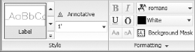
The Text Editor tab and its associated panels appear in the ribbon. In the Style and Formatting panels, you can see the current text style and its font and height, as shown in Figure 8.46. Just above the rectangle you defined, the Multiline Text Editor opens. This is where you'll enter the text.
Enter the following text, using single spacing and pressing
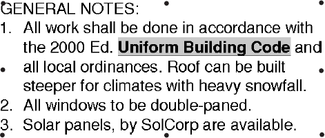
GENERAL NOTES:
All work shall be in accordance with the 2000 Ed. Uniform Building Code and all local ordinances.
Roof can be built steeper for climates with heavy snowfall.
All windows to be double-paned.
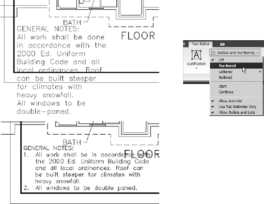
When you've finished, click a blank spot in the drawing area. The text appears in the drawing (see the top left of Figure 8.47). The window you specified was used only to define the line length. Its height doesn't control how far down the text comes; that is determined by how much text you enter. Before you adjust the text to fit the area, you will have AutoCAD add numbering to the notes.
Double-click anywhere on the new text to display the Multiline Text Editor and the MText panels.
Move the cursor to the upper-left corner of the window containing the text and in front of the A in the first word (All) of the first note. Hold down the left mouse button, and drag to the right and down until all the remaining text is highlighted. Release the mouse button.
Expand the Bullets and Numbering drop-down list in the Paragraph panel and then choose Numbered from the cascading menu that pops up (see the top right of Figure 8.47).


Use the grip at the upper-right corner of the text to stretch the text box further to the right. The text reconfigures to fit the new constraints (see the bottom of Figure 8.47).
Double-click the Mtext again. The Text Editor tab opens.
Highlight all the text again. In the Font drop-down list on the Formatting panel, select SansSerif as the current font. The selected text changes to the new font.
Click a point in the drawing area. The Mtext in the drawing becomes more compact, and there is room for more notes.
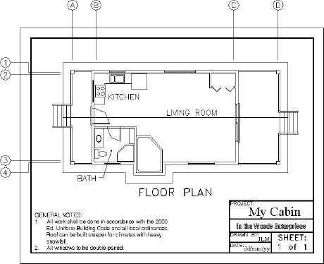
Move the text and title block down and to the left until the cabin fits neatly within the upper-border area and the notes are unobstructed (see Figure 8.48).
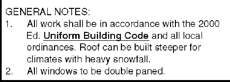
SansSerif is a TrueType font supported by Windows. When used in AutoCAD drawings, it can be italic or bold. To see how to change individual words within the text, you'll underline and bold the "Uniform Building Code" text:
Zoom in to and double-click the Mtext again.

Click in the drawing area. AutoCAD redraws the text with the changes (see Figure 8.49).
You can also italicize individual words and give them a different color or height from the rest of the Mtext by using the other tools on the Multiline Text panel. I encourage you to experiment with all these tools to become familiar with them.
You can easily alter the length of a line to make the Mtext fit more conveniently on the drawing. Let's say you've decided to put your company logo to the left of the title block. You need to squeeze the text into a narrower space. You have some extra room at the bottom, so you should be able to do it:
Move the Mtext up slightly, and then click the Mtext to select it. Two square grips appear at the upper corners of the body of Mtext and one arrow-shaped grip appears centered at the bottom.
On the status bar, be sure Polar Tracking and Object Snap are off. Then click the bottom-center grip to activate it.
Slowly move the cursor down as far as you can without causing the text box to dip below the border (see the top of Figure 8.50) and then click.
Select the upper-right grip, move it as far as you can to the left without causing the Mtext to form another column to the right of the existing column, and then click (see the bottom of Figure 8.50).
Reposition the text as necessary.
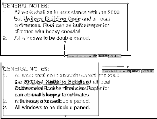
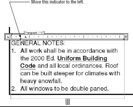
The ruler at the top of the Mtext Editor window has two sliding indicators for setting indentions. The top indicator is for the first line in the Mtext object and the first line after each
Double-click the text again.
In the Mtext Editor window, highlight the two notes.
Use the mouse to slide the bottom indicator on the ruler one notch to the left (see Figure 8.51). Click outside the text to save the changes. The notes are now a bit closer to the numbers.
You have the ability to add hyperlinks, links to web pages or files, to the body of an Mtext object. When a hyperlink to a URL exists, anyone with the drawing open can hold down the Ctrl button and click the link to open the associated page in their web browser. Hyperlinks can also point to local or network files, causing the file's associated application to open when they are clicked. Here is the procedure for adding a hyperlink:
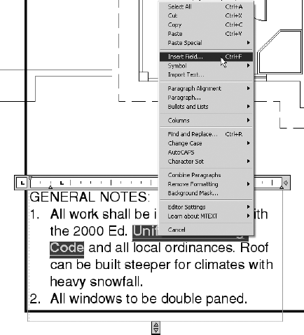
Double-click the Mtext object.
Highlight the text where you want the hyperlink to appear.
Right-click and choose Insert Field from the context menu (see Figure 8.52), or click the Field button in the Insert panel.
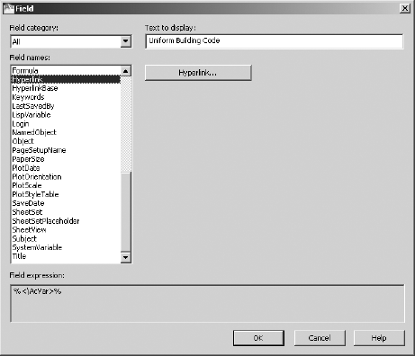
In the Field Names section of the Field dialog box that opens, select Hyperlink. In the Text to Display field, enter the text that you want to appear in the tooltip when the cursor hovers over the hyperlink (see Figure 8.53). In this case, it will be the same.
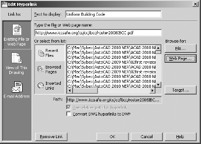
Click the Hyperlink button; then, in the Edit Hyperlink dialog box (see Figure 8.54), you can do any of the following:
Enter the web page or filename and path in the Type The File Or Web Page Name box.
Click the File button under Browse For to select a file to which to link the text.
Click the Web Page button under Browse For to navigate to the web page to which you want to link the text.
Perform one of these options, click the OK button to close this dialog box, and then click OK to close the Field dialog box.
Click a blank area to deselect the Mtext. The link appears as text with a gray background; the background doesn't appear in a printed drawing.
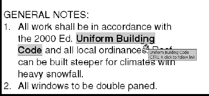
Hold the Ctrl key down, and hover the cursor over the gray background (see Figure 8.55). The cursor changes to the hyperlink cursor, and instructions to follow the link appear on a tooltip. With Ctrl still pressed, click the background. This minimizes AutoCAD, opens your browser, and navigates to the selected web page.
Perform a Zoom Extents, and then save this drawing as
Cabin08e.dwg. Your drawing should look like Figure 8.56.
Like most programs with word processing capability, AutoCAD includes a spell-check feature to identify potential spelling errors. The spell check can be run to look for errors in a selected single-line or multiline text object. There is also a real-time spell-check feature to spot misspellings as you type and to suggest alternative words. Follow these steps to see the spell-check feature in action:
Zoom into the notes at the bottom of the drawing area and move them up enough to allow space for one more line of text. Expand the Mtext window down to accommodate the next line of text.
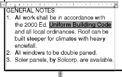
Double-click the notes, place the cursor just past the period at the end of the second note, and enter
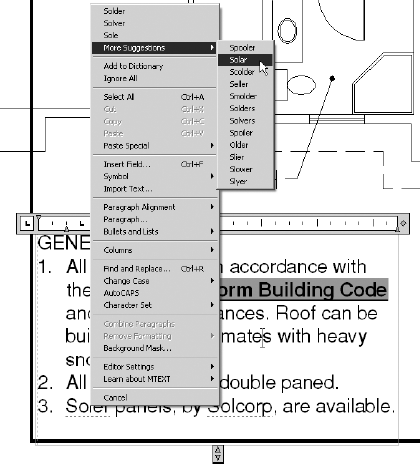
Notice how the words Soler and SolCorp are underlined with a dashed line (see Figure 8.57). This is how the real-time spell-check tool identifies the words the AutoCAD dictionary doesn't recognize.
Position the cursor in the word Soler, and right-click to open a context menu. At the top of the menu are spelling suggestions. Click or pause the cursor over the More Suggestions options; then click Solar, as shown in Figure 8.58. Soler is replaced with Solar in the selected Mtext.
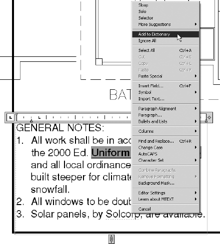
Many words that you frequently use, such as company, city, or individual names, may not exist in the AutoCAD dictionary and will be flagged as misspelled words. You can easily add words to the dictionary to eliminate these words from being flagged repeatedly.
Put the cursor in the word SolCorp, and right-click to open the context menu. Near the top of the menu, click Add To Dictionary (see Figure 8.59). SolCorp is added to the AutoCAD dictionary and is no longer underlined.
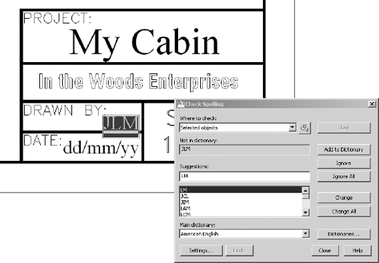
Often, drawings can have many separate text elements in the form of single-line text, multiline text, and dimensions. Although you can select each object individually, you can also run the Spell Check tool on the entire drawing. Here's how:

In the Check Spelling dialog box that opens, choose Entire Drawing in the Where To Check drop-down list and then click Start. AutoCAD checks the entire drawing for words that do not exist in the dictionary, highlights them, and offers suggestions for misspelled words, as shown in Figure 8.60.
When an unknown word is identified, you can:
Click Add To Dictionary to add the word to the AutoCAD dictionary.
Click Ignore to take no action and continue searching the drawing for misspelled words.
Click Ignore All to take no action and continue searching the drawing for misspelled words, ignoring all occurrences of the same word.
Select a word in the Suggestions list and then click Change to replace the flagged word with the suggested word.
Select a word in the Suggestions list and then click Change All to replace the flagged word with the suggested word and automatically substitute all occurrences of the flagged word for the suggested word.
When the spell-checking task is finished, click OK in the Spell Check Complete dialog box and click Close in the Check Spelling dialog box.
Perform a Zoom Extents, and then save this drawing as
Cabin08f.dwg.
Multiline text has several other features that I can only touch on in this book. I encourage you to experiment with any features that you might find useful to your work.
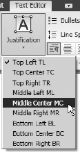
Mtext has justification points similar to those of single-line text, and they behave the same way. The default justification point for Mtext, however, is the upper-left corner of the body of text, and the available options are for nine points distributed around the perimeter of the body of text and at the center (see Figure 8.61).
When you need to modify the justification of Mtext, double-click the text to open the Mtext Editor and display the Text Editor tab and panels. In the Paragraph panel, click the Justification button and then click the justification preference from the fly-out menu, as shown in Figure 8.62. I'll describe the other items on this menu in the upcoming "Tools for Modifying Multiline Text" sidebar.
With Mtext, you can add special characters—the degree symbol, the diameter symbol, and so on—that aren't included in most font character packages. You'll have a chance to do this in Chapter 12, "Dimensioning a Drawing."
If you want to experiment with the Mtext in the cabin drawing, make a copy of it, and place it outside of the title block. Double-click it and see what you can learn about the Multiline Text Editor, the tools found in the panels located under the Multiline Text tab, and the Mtext shortcut menu. The "Tools for Modifying Multiline Text" sidebar summarizes the features of the latter two.
Trades and professions other than architecture and construction use text with AutoCAD and LT in the same way as demonstrated in this chapter.
For more practice using single-line text, follow these steps:
Close all drawings, and then open
Cabin04c-addon.dwg.Using the DesignCenter, bring in the Title and Label text styles from the
Cabin08edrawing while it's closed.Place labels on the features that were added:
Use the Title text style to identify the addition as GARAGE.
Use the Label text style to give the features the following names: WALKWAY, STORAGE, OFFICE, and CAR.
For more practice using Mtext, follow these steps:
Open
Cabin08f.dwg, and zoom in to the blank space between the notes and the title block.Create a new text style called Description that uses the Times New Roman font and a height of 8″ (204 mm).
Start Mtext, and specify a rectangle for the text that covers the area between the notes and the title bar.
Enter the following text exactly as shown here, spelling errors and all:
This is a design for a small vaction cabin. It contains approximately 380 square feet of living space and includes one bedroom and one bath. It can be adopted to provide shelter in all climates and can be modified to allow constuction that uses local building materials. Please sund all inquiries to the manufacturer.
Double-click the new text, and make these changes:
Correct all spelling errors using the Spell Check tool or real-time spell checking.
Change square feet to sq. ft.
Bold the following: one bedroom, one bath, all climates, and local building materials.
Italicize the last sentence.