
The floor plan of a complex building project might actually be a composite of several AutoCAD files that are linked together as external references to the current drawing. This enables parts of a drawing to be worked on at different workstations (or in different offices) while remaining linked to a central host file. In mechanical engineering, a drawing might similarly be a composite of the various subparts that make up an assembly.
External references, or xrefs, are .dwg files that have been temporarily connected to the current drawing and are used as reference information. The externally referenced drawing is visible in the current drawing. You can manipulate its layers, colors, linetypes, and visibility, and you can modify its objects, but it isn't a permanent part of the current drawing. Changes made to the xref's appearance, such as color or linetype, in the current drawing are not reflected in the xref source drawing.
External references are similar to blocks in that they behave as single objects and are inserted into a drawing in the same way. But blocks are part of the current drawing file, and external references aren't.
Blocks can be exploded back to their component parts, but external references can't; however, external references can be converted into blocks and become permanent parts of the current drawing. In Chapter 7, you were able to modify the window block and, in so doing, update all instances of the window block in the drawing without having to explode the block. With an external reference, you can apply the same updating mechanism. You can also edit an externally referenced drawing while in the drawing that references it. To manage external references, you need to learn how to set up an xref, manipulate its appearance in the host drawing, and update it.
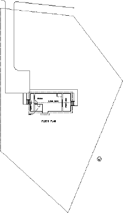
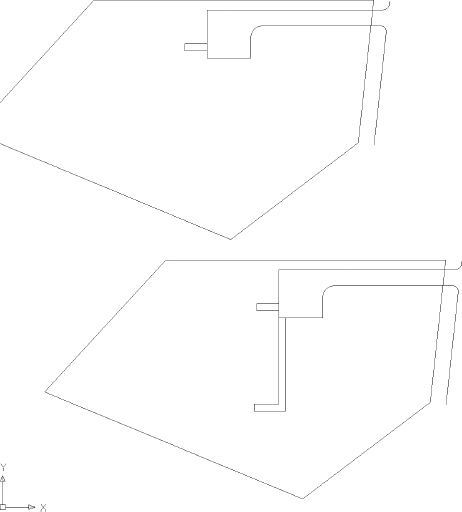
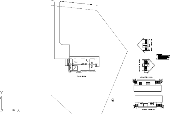
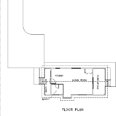
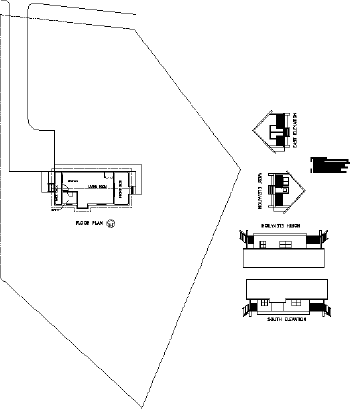
Before you set up the xref, you'll create a site plan for the cabin. You'll then externally reference the site plan drawing into the cabin drawing. In Figure 13.1, the lines of the site plan constitute the xref, and the rest of the objects are part of the host drawing. After these exercises, you'll look at a few ways that design offices use external references.
The site plan you'll use has been simplified so that you can draw it with a minimum of steps and get on with the external referencing. The following are the essential elements:
Property lines
Access road to the site
North arrow
Indication of where the building is located on the site
The first step is to draw the property lines.
You draw property lines using surveyor's units for angles and decimal feet for linear units. In laying out the property lines, you'll use relative polar coordinates: you'll enter coordinates in the format @distance<angle, in which the distance is in feet and hundredths of a foot and the angle is in surveyor's units to the nearest minute.
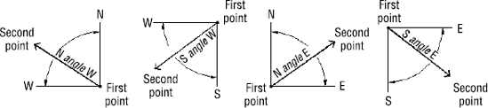
Surveyor's units, called bearings in civil engineering, describe the direction of a line from its beginning point. The direction (bearing), described as a deviation from the north or south toward the east or west, is given as an angular measurement in degrees, minutes, and seconds. The angles used in a bearing can never be greater than 90°, so bearing lines must be headed in one of the four directional quadrants: northeasterly, northwesterly, southeasterly, or southwesterly. If north is set to be at the top of a plot plan, then south is down, east is to the right, and west is to the left. Therefore, when a line from its beginning goes up and to the right, it's headed in a northeasterly direction; when a line from its beginning goes down and to the left, it's headed in a southwesterly direction; and so on. A line that is headed in a northeasterly direction with a deviation from true north of 30° and 30 minutes is shown as N30d30′E in AutoCAD notation. Figure 13.2 shown examples of a line drawn using surveyor's units.
With the surveyor's unit system, a sloping line that has an up-and-to-the-left direction has a down-and-to-the-right direction if you start from the opposite end. So, in laying out property lines, it's important to move in the same direction (clockwise or counterclockwise) as you progress from one segment to the next.
You'll set up a new drawing and then start at the upper-right corner of the property lines, working your way around counterclockwise:
Open
Cabin12d.dwgfrom yourTraining Datafolder (or the folder in which your training files are stored). From the Application menu, choose Save As

All the units in these first few sections are noted as architectural and, in a later section, I'll show you how to bring in a drawing using a different scale.

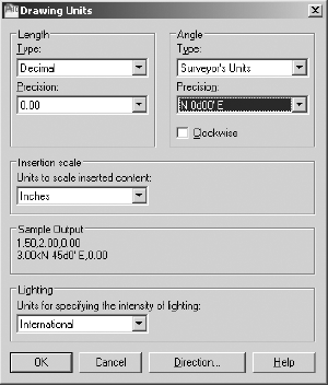
In the Angle area, open the Type drop-down list and select Surveyor's Units. Then change the Precision value to the nearest minute (N 0d00′ E). Your Drawing Units dialog box should look like Figure 13.3. Click OK.
From the menu bar, choose Format
Right-click the Snap Mode button on the status bar and choose Settings. Change Snap Spacing to 10.00, and change Grid Spacing to 0.00. Then select the Grid On check box to turn on the grid, but leave Snap off. Click OK.
Enter z

Create a new layer called Prop_Line. Assign it the color number 172 and make it current.
Turn on Dynamic Input in the status bar.
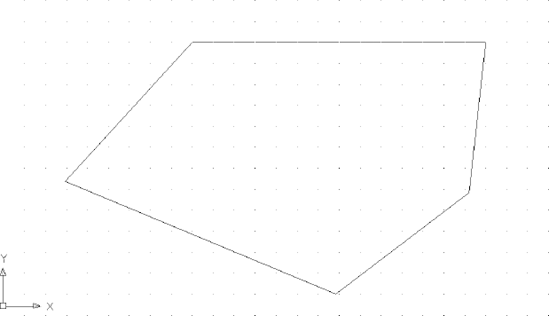
Start the Line command. For the first point, enter 220,130
Be sure Snap is turned off. Then enter the following:
@140<n90dw
@90<s42d30′w
@140<s67d30′e
@80<n52d49′e
c
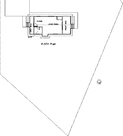
The property lines are completed (see Figure 13.5).
The driveway is 8′ wide and set in 5′ from the horizontal property line. The access road is 8′ from the parallel property line. The intersection of the access road line and the driveway lines forms corners, each with a 3′ radius. The driveway extends 70′ in from the upper-right corner of the property.
Let's lay this out now:
Open the Drawing Units dialog box again. Change the Length units to Architectural and the Angle units to Decimal Degrees. Then set the Length Precision to 0′−0 1/16″ and the angular precision to 0.00. Click OK.


Note
You can also start the Scale command by entering sc
Enter all
At the
Specify scale factor or [Copy/Reference]:prompt, enter 12Zoom to the drawing's extents, and then zoom out a little more. The drawing looks the same, but now it's the correct size. Check it with the Distance command, or dimension some of the lines. Delete any dimensions that you make (the value will appear in the Command window).
Offset the upper-horizontal property line 5′ down. Offset this new line 8′ down.
Offset the rightmost property line 8′ to the right (see the top of Figure 13.6) to show the limits of the access road.
Create a new layer called Road. Assign it the color White, and make the Road layer current.
Select the three new lines, open the Layer drop-down list in the Layers panel, and click the Road layer to move the selected lines to the Road layer. Press Esc to deselect the lines.
Extend the driveway lines to the access road line. Trim the access road line between the driveway lines.
Fillet the two corners where the driveway meets the road using a 3′ radius (see the bottom of Figure 13.6).
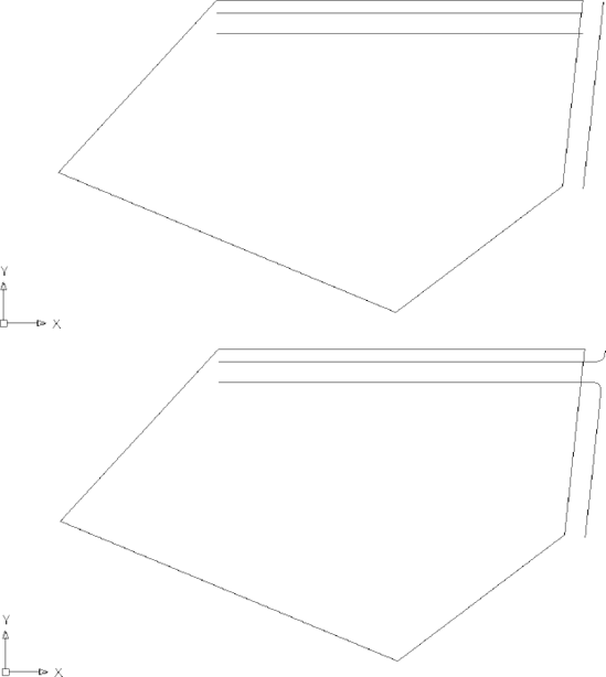
Figure 13.6. Offset property lines (top) and the completed intersection of the driveway and access road (bottom)
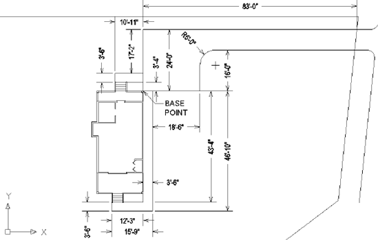
A key element of any site plan is information that shows how the building is positioned on the site relative to the property lines. Surveyors stake out property lines. The building contractor then takes measurements off the stakes to locate one or two corners of the building. In this site, you need only one corner because you're assuming the front door of the cabin is facing due east. A close look at Figure 13.1, shown earlier in this chapter, shows that the end of the driveway lines up with the top-rear corner of the cabin. Extending from the driveway are sidewalks that run to the front and rear steps. This locates the cabin on the site (see Figure 13.7).
Imagine the site being on the bluff of a hill overlooking land that falls away to the south and west, providing a spectacular view in that direction. To accommodate this view, you'll want to change the orientation of the site drawing when you externally reference it into the cabin drawing:
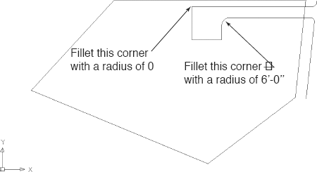
On the status bar, turn on Object Snap Tracking and make sure the Endpoint osnap is running. Then start a line with the first point 83′−0″ to the left of the intersection of the upper driveway line and the property line.
Draw the line straight down 24′−0″. Draw another line 22′−0″ to the right; then end the Line command.
Offset the vertical line 22′−0″ to the right. This will mark the end of the driveway.
Fillet the intersection of the upper driveway line and the left vertical line with a radius of 0 and the intersection of the lower driveway line and the right vertical line with a radius of 6′−0″ (see Figure 13.8).
To draw the rear sidewalk, use object snap tracking to draw a line that starts 3′−4″ up from the lower-left corner of the driveway to a point 10′−11″ to the left. Continue by drawing a line straight up 3′−6″ and then 10′−11″ back to the right before you terminate the Line command. See the top of Figure 13.9. You can refer back to Figure 13.7 to see the dimensions if necessary.
To draw the side and front sidewalk, start the Line command again. Then pick the lower-left corner of the driveway as the first point.
Either use the direct-entry method using the distances below to draw the remaining sidewalk lines, or enter the distances and angles as shown:
43′−4″ <270
12′−3″<180
3′−6″<270
15′−9″<0
46′−10″<90
The bottom of Figure 13.9 shows the completed side and front sidewalk. Press
We've been identifying east to the right of the cabin and north to the top. Now you'll add a north arrow to identify the directions to anybody looking at your drawing. Here's how:
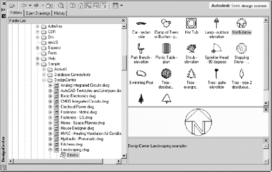
Make Layer 0 current and then open the DesignCenter.
Click the Folders tab and then navigate to the
Program Files/AutoCAD 2010/Sample/DesignCenter/Landscaping.dwgfile. Expand the drawing contents in the left pane of the DesignCenter. Then click Blocks to display the list of blocks in the right pane.Select the North Arrow block in the right pane, as shown in Figure 13.10.
Drag the block into the left side of your drawing, and then close the DesignCenter.
The north arrow is a little small, so scale it up to twice its current size and rotate it so that it points to the right.
Open the Layer Properties Manager dialog box and change the linetype for the Prop_Line layer to PHANTOM. (You'll have to load this linetype; review Chapter 6 if necessary.)
Enter ltscale
Finally, you need to set the base point; that is, the location that will be attached to the cursor when this drawing is inserted as a block or external reference. Type base
Save this drawing in your
Training Datafolder asSite13a.dwg.
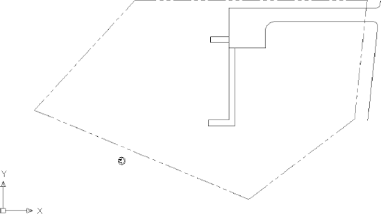
This completes the site plan. The next step is to attach the site plan as an external reference into the cabin drawing.
When you set up an external reference, you go through a process similar to that of inserting a block into a drawing, as you did in Chapter 7. You select the drawing to be referenced and specify the location of its insertion point. There are options for the X scale factor, Y scale factor, and rotation angle, as there are for inserting blocks. Here, as with blocks, you can set up the command so that it uses the defaults for these options without prompting you for your approval.
You can run all external reference operations through the External References palette, which you can open by clicking the Insert tab and then clicking the External References button on the Reference panel, or by entering xr
The following two series of steps will guide you through the process of attaching Site13a.dwg to Cabin13a.dwg as an xref:
With
Cabin13aas the current drawing, zoom to the drawing's extents and then create a new layer called Site. Assign color 162 as the layer color, and make the Site layer current.
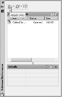
Click the Attach DWG button in the palette toolbar, as shown in Figure 13.12.
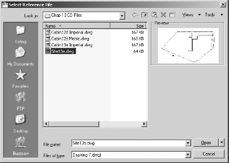
In the Select Reference File dialog box that opens, locate the
Training Datafolder (or the folder in which your training files are stored), and selectSite13a.dwg. A thumbnail image of the drawing appears in the Preview window, as shown in Figure 13.13.Click Open to open the External Reference dialog box, and then click the Show Details button in the bottom-left corner to display the reference paths (see Figure 13.14).
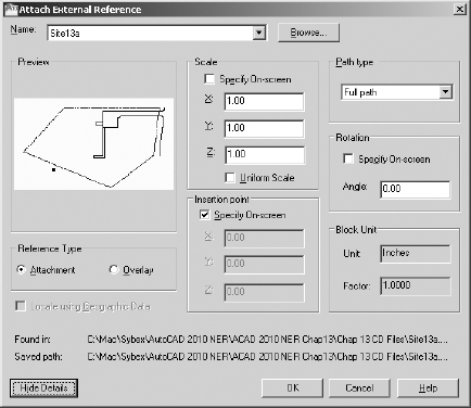
The file being referenced, Site13a, appears in the Name drop-down list at the top of the dialog box, with the full path of the file's location at the bottom. The right side of the dialog box contains three options for the insertion process, which are like those in the Insert dialog box that you used for inserting blocks in Chapter 7. Note that only the insertion point is set to be specified on the screen. The Scale and Rotation options should be set to use their default settings. If they aren't, click the appropriate check boxes so that this dialog box matches that in the previous graphic. Continue as follows:
Make sure Attachment is selected in the Reference Type area, and set the path type to Relative Path.
With the Full Path option selected, the referenced file is located at the absolute path specified and other users of the drawing must have the same file structure. The Relative Path option selects the file from a folder location, relative to the path used by the current file, with the current drawing location at the top of the path structure.
Click OK. You return to your drawing, and the site plan drawing appears and moves with the base point attached to the crosshair cursor.
Click at the top-left corner of the rear deck post to be the insertion point, and then zoom to the drawing's extents. The xref drawing is attached and appears in the site plan (see Figure 13.15).
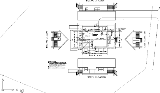
The attached xref appears exactly as it did when it was the current drawing. The drawing is cluttered now, and when you use this file as part of a site plan, or part of the cabin drawing, you don't want all the information to be visible. In fact, you want most of the information to be invisible. You'll accomplish this by freezing many of the layers in the drawing viewports, as explained in the next chapter. For now, you'll just move the elevations and notes out of the site area using a layer state to return to the current layer configuration. Here's how:

In the Layer States Manager dialog box, click New and then name this new state: Plan and Elev No Hatch.
Click OK to close the New Layer State to Save dialog box, and then Close to save the layer state and return to the drawing.
Turn on and thaw all the layers.
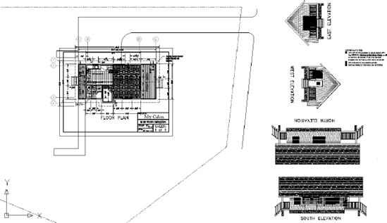
Carefully move the elevations and notes outside of the property line. Figure 13.16 shows the elevations stacked on the right side of the drawing area.
Open the Layer States Manager again, select the Plan and Elev No Hatch state, and click the Restore button. The layers return to their conditions when the layer state was saved.
Now you need to rotate the site plan to match the orientation of the cabin:
Freeze the Dim1 layer.
Start the Rotate command, click the site plan, and then press
To specify the insertion point of the xref as the rotation point, activate the Insert object snap, and then click any object from the site plan.
At the
Specify rotation angle or:prompt, enter 90
You have established Site13a as an external reference in this drawing. The next step is to make revisions to Site13a and see how they are reflected in the host drawing.
You can modify an xref drawing by making it the current drawing, making the modification, saving the changes, making the host drawing current, and reloading the xref. AutoCAD users can also modify an xref by using a special modification command while the host drawing is current. This section demonstrates both methods. You'll start by opening Site13a.dwg and adjusting the width of the road. Then you'll make Cabin13a current again and use AutoCAD to modify the site plan as an xref, changing the property line and moving the North arrow.
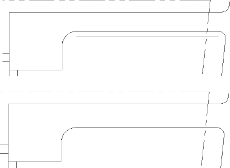
The longest part of the driveway is 8′−0″ wide, and we want to increase that to 10′−0″. You'll make the change in the site plan drawing and then reload it into the cabin drawing:
With
Site13aas the current drawing, zoom in to the area that includes the road and the driveway.Offset the lower road line 2′ downward, as shown in the top of Figure 13.18.
Fillet the right side with a radius of 3′ and the left at 6′.
Delete the original line and radii. Your driveway is now 10′ wide, as shown in the bottom of Figure 13.18.
Save the
Site13adrawing.Although you'll make more later, this concludes the modifications you'll make to the site plan in this exercise. Now you can return to the cabin drawing.
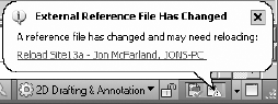
Switch to the
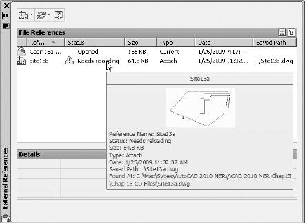
Cabin13afile. A balloon message appears at the bottom of the AutoCAD window (see Figure 13.19), pointing to the Manage Xrefs icon in the tool tray. This indicates that an externally referenced drawing has been saved after it was attached to the current drawing. You could click the blue link text to reload the file, but for this exercise, you will look at the External References palette and reload it from there.Open the External References palette, as shown in Figure 13.20, and stretch it to make it wider. The palette shows most of the pertinent information regarding the externally referenced files in the scene, including the status. When you pause the cursor over a reference, a cue card appears displaying a thumbnail image and additional information about that file. In this case, the palette indicates that
Site13aneeds reloading.Select the
Site13axref in the palette, right-click, and choose Reload from the context menu. This causes AutoCAD to reevaluate the external reference and update the current drawing. The cabin drawing now shows the 10′−wide access road from the site plan drawing (see Figure 13.21).Close the
Site13afile, but leave theCabin13afile open.Save the cabin drawing as
Cabin13b.dwg.
In this exercise, you saw how a host drawing is updated when the drawing that is externally referenced is made current, modified, saved, and then reloaded as an xref. Layers become an even more important tool when using external references. You can set them up one way in the actual drawing and another way in the xref of that drawing in a host file. In fact, you can externally reference the same drawing into any number of host files; have the layer characteristics of visibility, color, and linetype be different in each host file; and save them as such with each host file. External referencing is a powerful feature of AutoCAD, and you'll learn more about the possible applications of this tool toward the end of this chapter.
In Chapter 7, you used the Xref And Block In-Place Editing tool to update the window block. You can use the same tool here for editing an xref while the host drawing is the current drawing. You can't create a new layer with this tool, but many of the regular editing commands are available when you use it. You'll make a few modifications to the site plan xref to illustrate this feature.
In the
Cabin13bfile, make Layer 0 current.Zoom in to see the cabin and the lower portion of the property line (see Figure 13.22).
Note
The Edit In-Place command edits both blocks and xrefs. So, in AutoCAD's technical vocabulary for this command and its prompts, both blocks and xrefs are referred to as references.

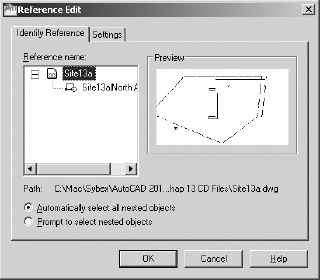
The Reference Edit dialog box opens (see Figure 13.23). On the Identify Reference tab,
Site13ais listed as the selected xref with the North Arrow blocks shown as a nested reference. A preview window illustrates the xref drawing.Click OK. The Edit Reference panel appears at the right end of the Ribbon.
Warning
If you have the AutoSave tool set to save your drawing automatically periodically (Application menu
You're now free to use many of the Draw and Modify commands on the site plan drawing that you just selected.
Open the Layer Properties Manager, and notice that several new layers now appear.
At the top are $0$Prop_Line and $0$Road, and lower in the list are Site-RefEdit0, Site13a|Prop_Line and Site13a|Road. The layer names separated by the pipe (|) symbol indicate that these are layers from the externally referenced
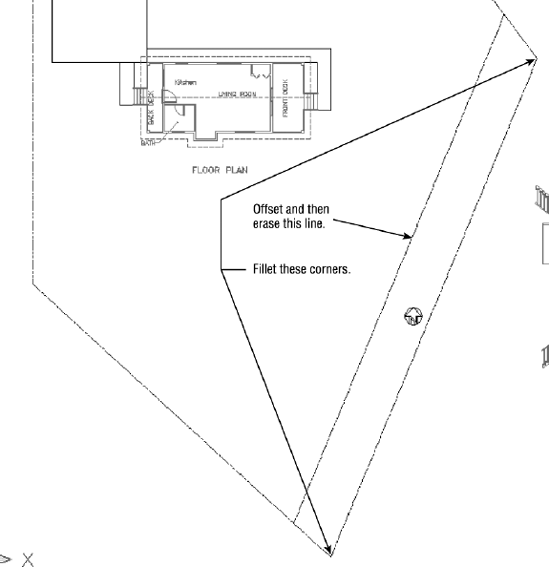
Site13drawing and are referred to as xref-dependent. Site13|Prop_Line and Site13a|Road appear in the Layer Properties Manager even when you are not editing an xref in-place. One restriction in the layer tools is that you can't make an xref-dependent layer current in the host drawing. The layers at the top of dialog box, the ones with the $ symbols, are temporary and will hold any objects created on them in the editing session and then shift those objects to the proper xref layer at the conclusion of the editing session.Make the $0$Prop_Line layer current, and then offset the lower-right diagonal property line 10′−0″ (3048 mm) to the right (see Figure 13.24).
Fillet the two lines that intersected with the line you just offset to the newly created line using a radius of 0. Erase the original line (see Figure 13.24).
Select the North arrow and move it closer to the floor plan, just to the right of the label.
Expand the Edit Reference panel, and click the Save Changes button.
When the warning dialog box opens, click OK. Your changes to the site plan are now saved back to the
Site13afile and the Edit In-Place tool is terminated.Use Zoom To Extents, and then zoom out a little to a view of the whole site (see Figure 13.25). Save this drawing. It's still named
Cabin13b.dwg.
In this exercise, you saw how a host drawing is updated when its external reference is changed and how you can control the appearance of objects in the xref drawing from the host drawing by working with the xref-dependent layers. You also saw how you can modify objects in the xref from the host drawing by using the in-place xref editing tool. A drawing can serve as an external reference in several host drawings at the same time and have a different appearance in each one, including location, rotation, and scale. The results of in-place xref editing, however, must be saved back to the original drawing in order to be viewed in the xref. In-place xref editing is usually done only when the results are meant to be permanent changes in the original source drawing.
Not only can you externally reference other drawing files into the current drawing, but you can also reference image files. Using this feature, you can add digital photographs or scanned images, such as artist renderings and construction forms, to a drawing. The procedure is similar to adding an externally referenced drawing; just follow these steps:
Create a new layer named Image, make it current, and then open the External References palette.
Right-click a blank area in the File References area below the existing filenames, and choose Attach Image from the context menu to open the Select Image File dialog box. You can also click the down arrow next to the Attach DWG button and choose Attach Image from the context menu.
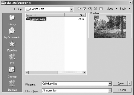
Most of the common image file formats are compatible with AutoCAD 2010. Navigate to the file that you want to attach, and then click the Open button (see Figure 13.26). A
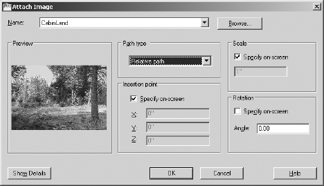
.jpgfile is included with the files on this book's web page,www.sybex.com/go/autocad2010ner.In the Attach Image dialog box that opens, similar to the External Reference dialog box that you saw earlier in this chapter, select Relative Path and the path type. Check the Specify On-Screen options for both Scale and Insertion point (see Figure 13.27), and then click OK.
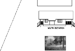
In the drawing area, click once to designate the lower-left corner of the image, move the cursor, and then click again to create the rectangular frame for the image. The image appears inside the frame (see Figure 13.28). The exact size and location of the frame are unimportant for this exercise, so ignore them for now. In the next chapter, you will decide how to view the image in the context of the rest of the drawing.
The
imageframevariable determines the visibility of the image frame and how it reacts when clicked. Setting the variable to 0 (zero) causes the frame to be invisible and also prevents the image from being selected or edited. Setting the variable to 1 displays the frame, allows it to be selected, and also shows the frame when the drawing is plotted (plotting is covered in Chapter 15). Settingimageframeto 2 displays the frame in the viewport and allows it to be selected, but does not show the frame when the drawing is plotted. This variable affects all the images in the drawing.Enter imageframe
Save the cabin drawing as
Cabin13c.dwg, and then close the file.
That's all there is to adding images to AutoCAD drawings. You can move and rotate the image using the same tools as with any other object. You can resize the image by selecting the frame and adjusting the grips. You get access to some rudimentary image-editing tools when you double-click the image frame. Feel free to experiment with them, but do not be concerned about altering the image file; these adjustments affect only the image's display inside AutoCAD.
External references have many different uses. I'll describe two common applications to illustrate their range.
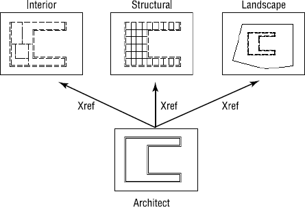
Suppose you're working on a project as an interior designer and a subcontractor to the lead architect. The architect gives you a drawing of a floor plan that is still undergoing changes. You load this file onto your hard drive in a specially designated folder, and then you externally reference it into your drawing as a background—a drawing to be used as a reference to draw over. You can now proceed to lay out furniture, partitions, and so on while the architect is still refining the floor plan.
At an agreed-on time, the architect gives you a revised version of the floor plan. You overwrite the one that you have on your computer with the latest version. You can then reload the xref into your furniture layout drawing, and the newer version of the floor plan will be the background. In this example, the lead architect might also send the same versions of the floor plan to the structural and mechanical engineers and the landscape architect, all of whom are working on the project and using the architect's floor plan as an xref in their respective host drawings (see Figure 13.29).
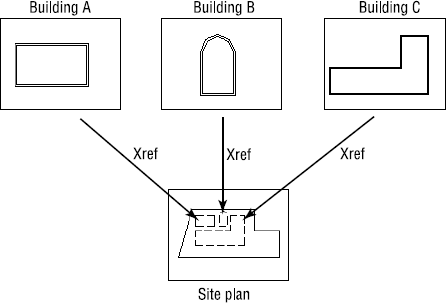
Xrefs are often used when parts of a job are being done in an office where a network is in place. Suppose a project involves work on several buildings that are all on the same site. If the project uses xrefs, each building can be externally referenced to the site plan. This keeps the site plan drawing file from getting too large and allows the project work to be divided among different workstations; in addition, the project manager can open the host site plan and keep track of progress on the whole project (see Figure 13.30).
These two applications for setting up xrefs in relation to a host file are applicable to almost any profession or trade using AutoCAD.
You have seen how you can modify an xref in the host or the original drawing and how to bring in images. A few other features of external references deserve mention.
When you attach an xref to the host drawing, AutoCAD stores the name of the xref and its path.
Note
The path of a drawing file is the name of the drive, folder, and subfolder where a file is stored, followed by the name of the drawing.
Each time you open the host drawing, AutoCAD searches for any xrefs saved with the host file and displays them in the host drawing. If the xref drawing is moved to a new folder after the xref has been attached to a host, AutoCAD won't be able to find the xref and can't display it. To avoid that situation, you must update the host drawing with the new path to the xref file. Let's go through a quick exercise to illustrate how this works:
Use Windows Explorer to create a new subfolder called
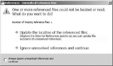
Xrefwithin theTraining Datafolder you previously set up. MoveSite13a.dwgto this folder.Return to AutoCAD, and open
Cabin13c.dwgagain. The xref doesn't show up, and the References—Unresolved Reference Files dialog box opens (see Figure 13.31).AutoCAD is unable to find the xref because the path has changed.
Click the Update the Location Of The Referenced Files option to open the External References palette.
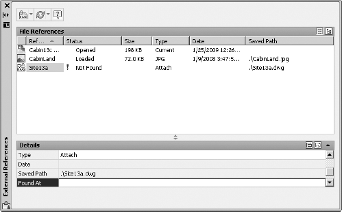
In the File References area where xrefs are listed, the path appears for each xref under the heading Saved Path (see Figure 13.32). The "." preceding the filename indicates that the current file path is relative and in the same folder as the current drawing. You can slide the scroll bar to the right—or widen the palette—to see the full path. Notice also that the Status column for this xref reads "Not Found."
Click the
Site13axref to highlight it. Move down to the Details area, and click the blank space to the right of Found At. A button with three dots appears at the right end of the blank space.Click the button. This opens the Select New Path dialog box. Find the
Site13adrawing in the newXreffolder. Highlight it and click Open.Back in the External References palette, the path has been updated to reflect the current location for
Site13a. Move or minimize the palette and then perform a Zoom Extents. You can see that the xref is restored in your drawing.
Warning
When you're working with xrefs, be careful where you store files that are acting as xrefs to other files. All the files' paths must remain valid for the xrefs to be located.
On occasion, you'll want to attach an xref to the host drawing permanently. If you send your drawing files to a printing service to be plotted, including a set of xref files can complicate things. Also, for archiving finished work, it might be better to reduce the number of files. There might also be occasions when the xref has been revised for the last time and no longer needs to be a separate file. In all these situations, you'll use the Bind command to convert an external reference into a block that is stored permanently in the host drawing:
In the External References palette, right-click
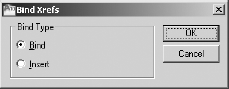
Site13ain the File References list.Choose Bind from the context menu to open the Bind Xrefs dialog box (see Figure 13.33).
The two options in the Bind Type area have to do with how layers are treated when an xref is bound to the host drawing. The default is Bind. It sets the xref layers to be maintained as unique layers in the host drawing. With the Insert option, layers that have the same name in the two drawings are combined into one layer. None of the layers in
Site13ahas the same name as any layers inCabin13c. Let's use the Insert option.Change the Bind Type to Insert and click OK. The xref disappears from the File References list.
Close the External References palette. Your drawing looks unchanged.
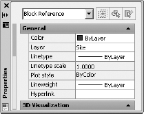
Click the site plan, and then open the Properties palette. The field at the top of the palette identifies the site plan as a block reference, as shown in Figure 13.34.
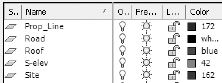
Open the Layer Properties Manager. Figure 13.35 shows that the site plan's layers have all become layers in the
Cabin13cdrawing and no longer have theSite13a|prefix.
Close the drop-down list by clicking a blank portion of the dialog box. Then click Cancel to return to your drawing. The site plan is now a permanent part of the
Cabin13cdrawing. If you need to make changes to the site plan part of the drawing, you can explode it and use the Modify commands. Or, you can use the In-Place Xref and Block Edit tool that you used previously in Chapter 7 to modify the window block.You do not want to save the changes in this drawing. Click the Close button in the top-right corner of the drawing area, and then click No in the dialog box that opens.
Move the
Site13afile back into theTraining Datafolder where it was prior to starting the exercises in the "Exploring Additional Xref Features" section.
This has been a quick tour of the basic operations used to set up and control external references. There are more features and commands for working with xrefs than I've covered here, but you now know enough to start working with them.
What follows are a few additional operations and features that you might find useful when you delve more deeply into external references. Play around a little, and see what you can do:
Externally referenced drawings can also be hosts and have drawings externally referenced to them. These are called nested xrefs. There is no practical limit to the number of levels of nested xrefs that a drawing can have.
You can't explode an xref, but you can detach it from the host. The Detach command is on the context menu that appears when you right-click an xref in the External References palette.
Large, complex drawings that are externally referenced often have their insertion points coordinated in such a way that all xrefs are attached at the 0,0 point of the host drawing. This helps keep drawings aligned properly. By default, any drawing that is externally referenced into a host drawing uses 0,0 as its insertion point. However, you can change the coordinates of the insertion point with the Base command. With the drawing you want to change current, enter base
You can limit which layers, and to some degree, which objects in a drawing are externally referenced in the host drawing by using indexing and demand loading.
A host drawing can be externally referenced into the drawing that has been externally referenced into the host, causing a circular reference. This is called an overlay and is an option in the Attach Xref dialog box. Overlays ignore circular xrefs.
If you freeze the layer that was current when an xref was attached, the entire xref is frozen. Turning off this same layer has no effect on the visibility of the xref.
The Unload option, available when you right-click a reference in the External References palette, lets you deactivate xrefs without detaching them from the host file. They stay on the list of xrefs and can be reloaded at any time with the Reload option. This option can be useful when you're working with complex drawings that have many xrefs.
In this chapter, you externally referenced the site plan drawing into the cabin drawing as an architect who was designing the project might have done. If you were the architect, you might want to have several additional drawings. Try doing this:
Create several new drawings of furniture and a shed. Each object is to have its own layer. Make more than one drawing for some of the objects, such as two beds or tables.
Add digital images on their own layers that show real-world examples of the furniture.
Externally reference all the furniture and shed drawings into the cabin drawing.
Use the Layer States Manager, as covered in Chapter 6, to create layer states for each combination of furniture.