
Dimensions are the final ingredient to include with your cabin drawing. To introduce you to dimensioning, I'll follow a pattern similar to the one I used in Chapter 8, "Controlling Text in a Drawing." You will first create a dimension style that contains the properties for the dimensions, and then you will add the dimensions themselves.
Dimension styles are similar to text styles but give you more options to control. You set them up in the same way, but many parameters control the various parts of dimensions, including the dimension text.
Before you start setting up a dimension style, you need to make a few changes to your drawing to prepare it for dimensioning:
Open
Cabin11c.dwg, the cabin with the hatch patterns added to all the views, and zoom in to the upper half of the drawing. If you didn't complete the "If You Would Like More Practice" section in the previous chapter, you can download the file from the book's website or continue with theCabin11b.dwgfile you created.Create a new layer called Dim1. Assign white as its color, and make it current.
Freeze all the remaining layers except 0, Deck, Doors, Roof, Steps, Text1, Walls, Windows, Foundation, and all the elevations.
Set the Endpoint and Midpoint object snaps to be running.
Set the status bar so that only the Object Snap and Dynamic Input buttons are in their on positions.
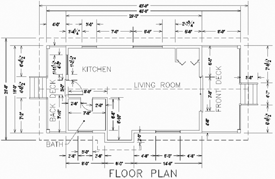
Click the Annotate tab. Your drawing will look like Figure 12.1.
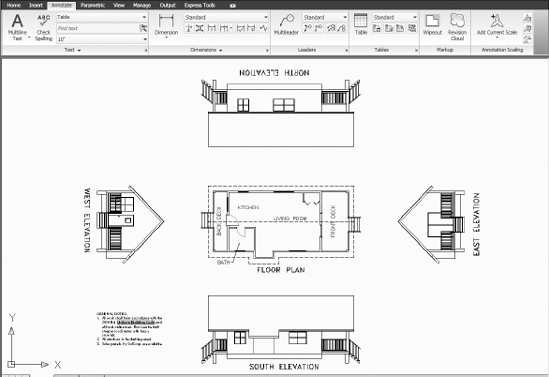
Figure 12.1. The cabin floor plan and elevations with the Annotate panels at the top of the drawing area
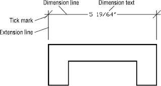
Each dimension has several components: the dimension line, arrows or tick marks, extension lines, and the dimension text (see Figure 12.2). An extensive set of variables stored with each drawing file control the appearance and location of these components. You work with these variables through a series of dialog boxes designed to make setting up a dimension style as easy and trouble free as possible. Remember that AutoCAD is designed to be used by drafters from many trades and professions, each of which has its own standards for drafting. To satisfy these users' widely varied needs, AutoCAD dimensioning features have many options and settings for controlling the appearance and placement of dimensions in drawings.
Every dimension variable has a default setting, and these variables as a group constitute the default Standard dimension style. As in defining text styles, the procedure is to copy the Standard dimension style and rename the copy—in effect making a new style that is a copy of the default style. You then make changes to this new style so it has the settings you need to dimension your drawing and save it. Follow these steps:

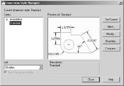
With Standard (ISO-25) highlighted in the Styles window, click the New button on the right side of the Dimension Style Manager dialog box to open the Create New Dimension Style dialog box shown in Figure 12.4.
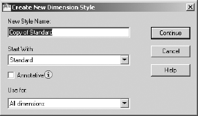
In the New Style Name field, Copy of Standard (ISO-25) is highlighted. Enter DimPlan, but don't Press

Notice that Standard (ISO-25) is in the Start With drop-down list just below. Because it's the current dimension style in this drawing, the new dimension style you're about to define will begin as a copy of the Standard style. This is similar to the way in which new text styles are defined (as you saw in Chapter 8). The Use For drop-down list allows you to choose the kinds of dimensions to which the new style will be applied. In this case, it's all dimensions, so you don't need to change this setting.
Click the Continue button. The Create New Dimension Style dialog box is replaced by the New Dimension Style: DimPlan dialog box (see Figure 12.5). It has seven tabs containing parameters that define the dimension style. You have created a new dimension style that is a copy of the Standard style, and now you'll make the changes necessary to set up DimPlan to work as the main dimension style for the floor plan of the cabin.
Be sure the Lines tab is active (on top). If it's not, click it.
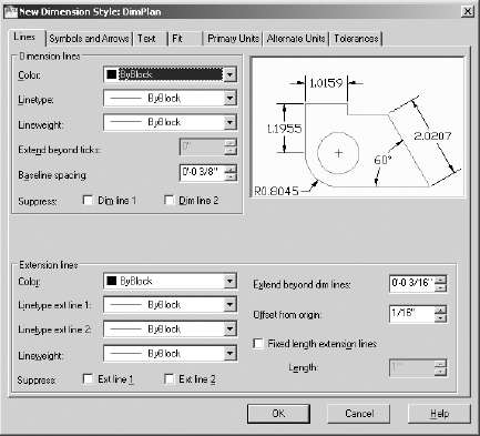
You'll use the Lines tab to control the appearance of the dimension and extension lines. In most cases, the color, linetype, and lineweight should stay at their default ByBlock value, indicating that an object inherits its color from the block containing it.
In the Extension lines area, change the Offset from origin setting from 1/16″(0.63) to 1/8″ (1.25) to increase the gap between the beginning of the extension line and the object being dimensioned.
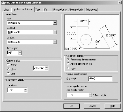
The Symbols and Arrows tab has settings that control the appearance of arrowheads and other symbols related to dimensioning:
Click the Symbols and Arrows tab and then, in the Arrowheads area, click the down arrow in the First drop-down list to open the list of arrowheads.
Click the Open 30 option. The drop-down list closes with Open 30 displayed in the First and Second drop-down lists. In the preview window to the right, a graphic displays samples using the new arrowhead type.
Select Open 30 from the Leader drop-down list as well.
Set the Arrow Size parameter to 1/8″ (3.5). After the changes, the tab should look like Figure 12.6.
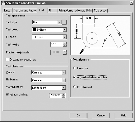
The settings in the Text tab control the appearance of dimension text and how it's located relative to the dimension and extension lines:
Click the Text tab in the New Dimension Style dialog box. Settings in three areas affect the appearance and location of dimension text. Look ahead to Figure 12.7 to see the Text tab. The preview window appears in all tabs and is updated automatically as you modify settings. Move to the Text Appearance area in the upper-left corner of the dialog box, where six settings control how the text looks. You're concerned with only two of them.

Arial font
0′−0″ (0) height
0.8000 width factor
All other settings at their default
If you need a reminder about creating text styles, refer to Chapter 8. Apply this text style, click the Set Current button, and then close the Text Style dialog box.
Back in the Text tab, open the Text Style drop-down list and select the new Dim style from the list.
Tip
Setting the text height to 0′0″ (0) in the Text Style dialog box allows the Text Height parameter of the dimension style to dictate the actual height of the text in the drawing. This allows many different dimension styles to use the same text style, each producing text with different heights. If you give the text a non-zero height in the Text Style dialog box, then that height is always used and the Text Height parameter of the dimension style is disregarded.
Set the Text Height value to 1/8″ (3.5).
Move down to the Text Placement area. These settings determine where the text is located, vertically and horizontally, relative to the dimension line. You need to change two settings here; make sure both the Horizontal and Vertical options are set to Centered.
Move to the Text Alignment area. The radio buttons control whether dimension text is aligned horizontally or with the direction of the dimension line. The ISO Standard option aligns text depending on whether the text can fit between the extension lines. Only one of the buttons can be active at a time. Horizontal should already be active. Click the Aligned With Dimension Line button. Notice how the appearance and location of the text changes in the preview window. This finishes your work in this tab; the settings should look like those in Figure 12.7.
This dialog box has four more tabs with settings, but you'll be making changes in only two of them: Fit and Primary Units.
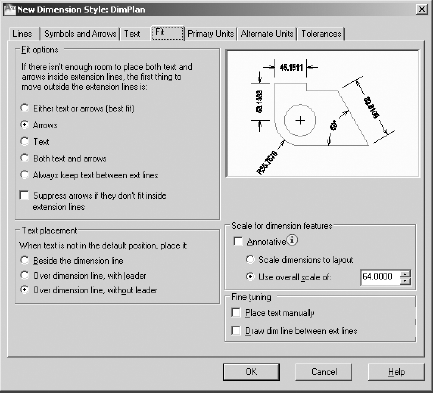
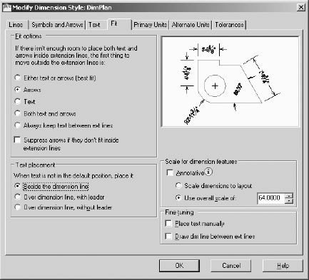
The settings on the Fit tab control the overall scale factor of the dimension style and how the text and arrowheads are placed when the extension lines are too close together for both text and arrows to fit:
Click the Fit tab in the New Dimension Style dialog box. Figure 12.8 shows the Fit tab as you'll set it.
In the upper-left corner, in the Fit Options area, click the Arrows radio button. This causes the arrows to be moved from between the extension lines to outside the dimension lines when they won't fit properly.
In the Text Placement area, click the Over Dimension Line, Without Leader radio button.
Move to the Scale For Dimension Features area. Be sure the Use Overall Scale Of radio button is active. Set the scale to 64 (70). In the Fine Tuning area, uncheck Draw Dim Line Between the Ext Lines. The settings on the Fit tab should look like those in Figure 12.8.
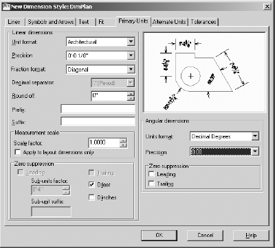
If your drawing is set up to use Architectural units, continue with this section. If you are using decimal units, skip this section and continue with the next section, "Setting Up the Primary Units Tab (Metric)." In the preview window, you might have noticed that the numbers in the dimension text maintain a decimal format with four decimal places, rather than the feet and inches format of the current architectural units. Dimensions have their own units setting, independent of the basic units for the drawing as a whole. On the Primary Units tab, you'll set the dimension units:
Click the Primary Units tab, and take a peek ahead at Figure 12.9 to see how it's organized. It has two areas: Linear Dimensions and Angular Dimensions, each of which has several types of settings.
In the Linear Dimensions area, starting at the top, make the following changes:
Change the Unit Format setting from Decimal to Architectural.
Change the Precision setting to 0′−0 1/8″.
Change the Fraction Format setting to Diagonal.
In the Zero Suppression area, uncheck 0 inches.
Note
Zero Suppression controls whether the zero is shown for feet when the dimensioned distance is less than one foot and also whether the zero is shown for inches when the distance is a whole number of feet. For the cabin drawing, you'll suppress the zero for feet, but you'll show the zero for inches. As a result, 9″ will appear as 9″, and 3′ will appear as 3′−0″.
In the Angular Dimensions area, leave Decimal Degrees as the Units Format setting and change Precision to two decimal places, as you did for the basic drawing units in Chapter 3, "Setting Up a Drawing." For now, leave the Zero Suppression area as it is. After these changes, the Primary Units tab looks like Figure 12.9.
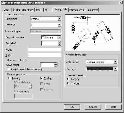
If your drawing is set up to use Architectural units, and you've completed the previous section, then skip this section and continue with the next section, "Completing the Dimension Style Setup." In the preview window, you might have noticed that the numbers in the dimension text maintain a decimal format with four decimal places rather than the feet and inches format of the current architectural units. Dimensions have their own units setting, independent of the basic units for the drawing as a whole. On the Primary Units tab, you'll set the dimension units:
Click the Primary Units tab, and take a peek ahead at Figure 12.10 to see how it's organized. It has two areas: Linear Dimensions and Angular Dimensions, each of which has several types of settings.
In the Linear Dimensions area, starting at the top, make the following changes:
Make sure Unit Format is set to Decimal.
Change the Precision setting to 0.
In the Suffix box, enter mm
In the Zero Suppression area, make sure Leading is checked and Trailing is not.
Note
Zero Suppression controls whether the zero is shown for measurements when the dimensioned distance is less than one millimeter and whether the zero is shown when the final digits, to the right of the decimal point in the dimension, are zeros. For the cabin drawing, you'll suppress the trailing zeros but not the leading zeros. As a result,.9500 will appear as 0.95 with Precision set to 0. This won't be a factor during these exercises
In the Angular Dimensions area, leave Decimal Degrees as the Units Format setting and change Precision to two decimal places, as you did for the basic drawing units in Chapter 3. For now, leave the Zero Suppression area as it is. After these changes, the Primary Units tab looks like Figure 12.10.
Of the last two tabs, any industry involved in global projects may use the Alternate Units tab, and the mechanical engineering trades and professions use the Tolerances tab. You won't need to make any changes to these tabs for this tutorial, but you'll take a brief look at them in the following sections.
It's time to save these setting changes to the new DimPlan dimension style and begin dimensioning the cabin:
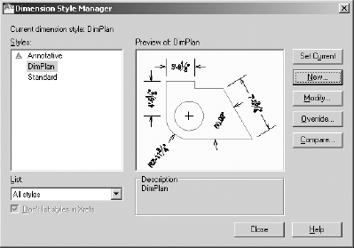
Click the OK button at the bottom of the New Dimension Style dialog box. You're returned to the Dimension Style Manager dialog box (see Figure 12.11).
DimPlan appears with a gray background in the Styles list box, along with Standard and Annotative. In the lower-right corner of the dialog box, in the Description area, you'll see the name of the new style. See Table 12.1, later in this section, as a reference for the differences between the Standard style that you started with and the DimPlan style.
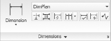
Click DimPlan to highlight it in a dark blue; then click the Set Current button. Finally, click the Close button. You're returned to your drawing, and the Dimensions panel displays DimPlan in the Dimension Style drop-down list, as shown in Figure 12.12. This indicates that DimPlan is now the current dimension style.
Save your drawing as
cabin12a.dwg.
You have made changes to 16 settings that control dimensions. This isn't too many, considering that there are more than 50 dimension settings. Table 12.1 summarizes the changes you've made so that the dimensions will work with the cabin drawing.
Table 12.1. Changes Made So Far
Tab | Option | Default Setting | DimPlan Setting |
|---|---|---|---|
Lines | Offset From Origin | 0′−0 1/16″ (0.63) | 0′−0 1/8″ (1.25) |
Symbols and Arrows | First | Closed Filled | Open 30 |
Second | Closed Filled | Open 30 | |
Leader | Closed Filled | Open 30 | |
Ext. Line – Extend Beyond Ticks | 3/16″ (2.5) | 1/8″ (3.5) | |
Arrow Size | 3/16″ | (2.5) 1/8″ (3.5) | |
Text | Text Style | Standard | Dim |
Text Alignment | Horizontal | Aligned With Dimension Line | |
Text Height | 3/16″ (2.5) | 1/8″ (3.5) | |
Fit | Fit Options | Either Text or Arrow (Best Fit) | Arrows |
Text Placement | Beside The Dimension Line | Over Dimension Line, Without Leader | |
Overall Scale | 1.0000 (1) | 64.0000 (70) | |
Primary | Unit Format | Decimal | Architectural (Decimal) |
Units | |||
Fraction Format | Horizontal | Diagonal | |
Zero Suppression | Feet, Inches (Trailing Only) | Feet Only | |
Angular Precision | Zero decimal places | Two decimal places |
You'll change a few more settings throughout the rest of this chapter as you begin to dimension the cabin in the next set of exercises. We'll now look briefly at the Alternate Units and Tolerances tabs.
Note
The next two sections describe dimensioning features that you won't use in the cabin project. If you would rather begin dimensioning the cabin and look at this material later, skip to the "Placing Dimensions on the Drawing" section.
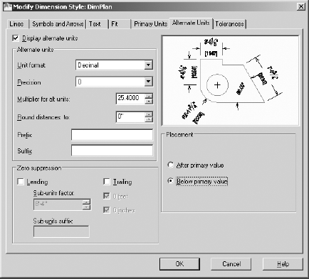
If your work requires your dimensions to display both metric and architectural units, use the Alternate Units tab in the New Dimension Style dialog box or the Modify Dimension Style dialog box when you are changing an existing style. In the example shown in Figure 12.13, the primary units setting is Architectural (Decimal). Now you'll set up the alternate units:

Highlight DimPlan in the Dimension Style Manager, if it's not already highlighted.
Click the Modify button to open the Modify Dimension Style dialog box. This is identical to the New Dimension Style dialog box that you used in the previous sections.
Click the Alternate Units tab. (Look ahead to Figure 12.13 to see what the style will look like when you're finished here.) You'll make only three or four changes on this tab.
In the upper-left corner of the tab, select the Display Alternate Units check box. This makes the rest of the settings on the tab available to you for making changes.
If Decimal (Architectural) isn't displayed in the Unit Format drop-down list, select it.
If Precision isn't set to 0 (0′−0 1/8″), open that drop-down list and select that level of precision.
If the alternate units is Decimal, then set Multiplier For Alt Units to 25.4. This makes millimeters the alternate units. If the alternate units is Architectural, then set Multiplier For Alt Units to 0.039370. This makes inches the alternate units.
In the lower-right quarter of the tab, in the Placement area, select Below Primary Value. This has the effect of placing the alternate units below the primary units and on the opposite side of the dimension line. The tab should look like Figure 12.13.
Uncheck the Display Alternate Units check box; you don't need use these settings. You won't be using alternate units when you dimension the cabin.
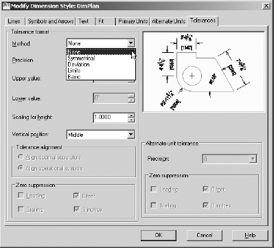
AutoCAD offers features whose options help you create several kinds of tolerances (allowable variances from the stated dimension). These are very common in the machining and manufacturing industries where it's understood that the dimensions given are only approximations of the part fabricated. Tolerances are usually measured in thousandths of an inch or hundredths of a millimeter. The Tolerances tab provides four methods for creating what are called lateral tolerances, the traditional kind of tolerance that most drafts people use. This is the plus or minus kind of tolerance. Open the Modify Dimension Style dialog box, click the Tolerances tab, and look at the choices in the Method drop-down list, shown in Figure 12.14.
Each of these is a method for displaying a plus or minus type of tolerance:
- None
No tolerances are displayed.
- Symmetrical
This method is for a single plus or minus expression after the base dimension. It's used when the upper allowable limit of deviation is identical to that for the lower limit, as in 1.0625 ± 0.0025.
- Deviation
This method is for the instance in which the upper allowable deviation is different from that of the lower deviation. For example, the upper limit of the deviation can be +0.0025, and the lower limit can be −0.0005. The two deviation limits are stacked and follow the base dimension.
- Limits
In this method, the tolerances are added to or subtracted from the base dimension, resulting in maximum and minimum total values. The maximum is placed over the minimum. In the example for the Symmetrical method, 1.0650 is the maximum and on top of 1.0600, the minimum.
- Basic
The base dimension is left by itself, and a box is drawn around it indicating that the tolerances are general, apply to several or all dimensions in boxes, and are noted somewhere else in the drawing. Often, basic dimensions appear when a dimension is theoretical or not exact.
When you select one of these options, one or more of the settings below become available. If you select Deviation or Limits, all settings become available:
- Precision
Controls the overall precision of the tolerances.
- Upper Value and Lower Value
- Scaling For Height
The height of the tolerance text. A value of 1 here sets the tolerance text to match that of the base dimension. A value greater than 1 makes the tolerance text greater than the base dimension text, and a value less than 1 makes it smaller than the base dimension text.
- Vertical Position
Where the base dimension is placed vertically relative to the tolerances. It can be in line with the upper or lower tolerance or in the middle.
At the bottom, when checked the Zero Suppression options (which are not available when Basic is the tolerance format) suppress extra zeros that occur before or after the decimal point. If you set up the Tolerances tab as shown in the top of Figure 12.15, a dimension looks like the one shown in the bottom of Figure 12.15.
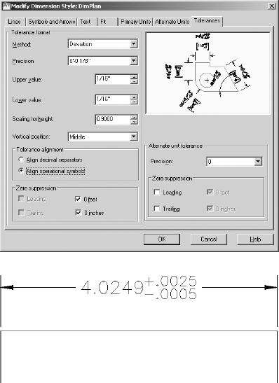
Figure 12.15. The Tolerances tab with some settings changed (top) and a dimension with deviation tolerances (bottom)
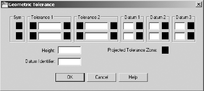
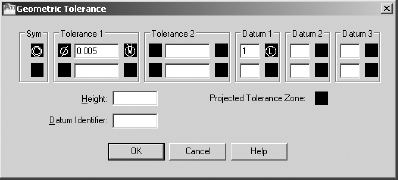
A more complex family of tolerances is available through the Dimensions panel. It's called geometric tolerancing and involves setting up a series of boxes that contain symbols and numbers that describe tolerance parameters for form, position, and other geometric features. Usually two to six boxes appear in a row, with the possibility of multiple rows. These all constitute the feature control frame, which eventually is inserted in the drawing and attached in some way to the relevant dimension. Follow these steps:

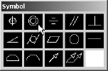
Click in the top Sym box on the left to open the Symbol dialog box, which contains 14 standard symbols that describe the characteristic form or position for which the tolerance is being used. When you select one of the symbols, the window closes, and the symbol is inserted into the SYM box. Click the icon in the top row that consists of two concentric circles, as shown in Figure 12.17.
Click the top-left black square in the Tolerance 1 area. This inserts a diameter symbol.
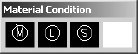
Click the top-right black square of Tolerance 1. The Material Condition dialog box (see Figure 12.18) opens and displays the three material condition options. When you click one, it's inserted in the top-right square of Tolerance 1.
If you need them, you can insert any of these three symbols in Tolerance 2 and Datum 1, 2, or 3.
Fill in the actual tolerance value(s) and datum references in the text boxes. (See Figure 12.19.)
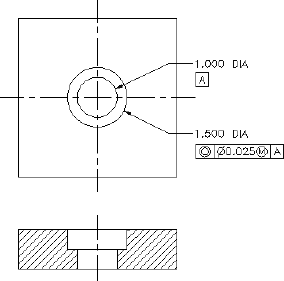
When you're finished, click OK. You can insert the feature control frame into your drawing like a block and reference it to a part or a dimension, as shown in Figure 12.20.
This exercise was intended to show you the tools that AutoCAD provides for setting up the most commonly used lateral and geometric tolerances when you use the Tolerances tab in the Modify Dimension Style dialog box and the Tolerance button on the Dimensions panel. My intention here isn't to explain the methodology of geometric tolerances or the meanings of the various symbols, numbers, and letters used in them. That is a subject beyond the scope of this book.
Upon returning to your drawing, it should still look almost exactly like Figure 12.1 (shown earlier), and it should have the following:
A new layer called Dim1, which is current
A new dimension style called DimPlan, which is current and is now displayed in the drop-down list on the Dimensions panel
Most of the layers frozen
The Endpoint osnap running (other osnaps may be running, but only Endpoint is important to this exercise)
On the status bar: Ortho Mode, Polar Tracking, and Object Snap Tracking off
A new text style called Dim, which is current
First, you'll dimension across the top of the plan, from the corner of the building to the closet wall, and then to the other features on that wall. Then you'll dimension the decks and roof.

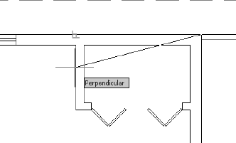
Pick the upper-right corner of the cabin walls. The prompt changes to
Specify second extension line origin:. At this point, zoom in to the closet area.Activate the Perpendicular osnap, place the cursor over the outside of the closet wall as shown in Figure 12.21, and then click.
At the
Specify dimension line location or:prompt, click a point above the roof line to place the dimension in the drawing (see the top of Figure 12.22). Also notice that the left extension line starts perpendicular to the wall you picked.Click anywhere on the new dimension. The dimension becomes dashed and five grips appear (see the bottom of Figure 12.22). When you need to adjust a dimension, click and drag the necessary grip. You'll learn more about using grips to modify dimensions in the "Modifying Dimensions" section later in this chapter.
Press Esc to deselect the dimension.
Your first dimension is completed.
When dimensioning a drawing, you usually dimension to the outside or center line of the objects and to each significant feature. The next dimension will run from the left side of the first dimension to the right side of the window.
Note
Studs are the vertical 2″×4″ (51 mm×102 mm) or 2″×6″ (51 mm×152 mm) members in the framing of a wall. When dimensioning buildings that have stud walls, architects usually dimension to the face of the stud rather than the outside surface of the wall material, but I won't go into that level of detail in this book.
AutoCAD has an automatic way of placing adjacent dimensions in line with one another—the Continue command. You use it as follows:
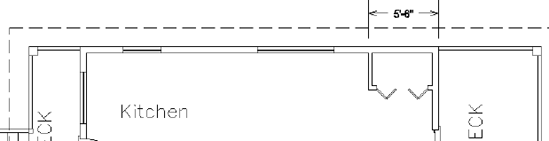
Zoom out, and pan until you have a view of the upper wall and roofline, with space above them for dimensions (see Figure 12.23).

Click the right corner of the living room window. This draws the second dimension in line with the first (see Figure 12.24). Note that the same prompt has returned to the Command window. You can keep picking points to place the next adjacent dimension in line.
Continue adding dimensions with the Continue command by clicking, moving right to left, the endpoints of the window openings, the endpoint of the wall, and the end of the deck.
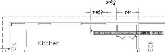
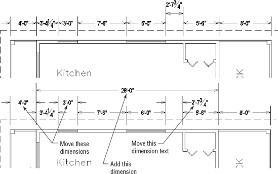
Use the Linear tool to add a dimension for the width of the front deck and the Perpendicular osnap to align the dimension lines. When you're done, your dimensions should look like the top of Figure 12.25.
Some of the dimensions, particularly on the left end of the cabin, appear cluttered with some of the arrowheads and text overlapping. Select the dimensions that need adjustment and use the grips near the arrows or at the text to adjust the dimension line or text location (see the bottom of Figure 12.25).
Finally, add a linear dimension from the end of the front deck to the beginning of the cabin and another overall dimension from one end of the cabin to another (see the bottom of Figure 12.25).
With the Continue command, you can dimension along a wall of a building quickly just by picking points. AutoCAD assumes that the last extension line specified for the previous dimension will coincide with the first extension line of the next dimension. If the extension line from which you need to continue isn't the last one specified, Press
Another automation strategy that you can use with linear dimensions is the Baseline command.
The Baseline command gets its name from a style of dimensioning called baseline, in which all dimensions begin at the same point (see Figure 12.26). Each dimension is stacked above the previous one. Because of the automatic stacking, you can use the Baseline command for overall dimensions. AutoCAD will stack the overall dimension a set height above the incremental dimensions.
The steps for creating baseline dimensions are listed here:
Create a linear dimension.

Pick the next feature to be dimensioned.
Repeat step 3 as necessary to add the required dimensions.
Press Esc to end the Baseline command.
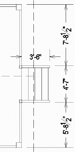
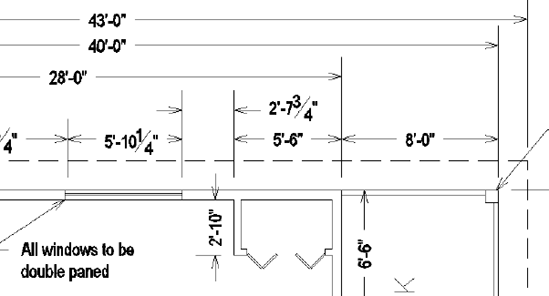
Because you can use the Linear command for vertical and horizontal dimensions, you can follow the steps in the previous exercise to do the vertical dimensions on the right side of the floor plan. The only difference from the horizontal dimensioning is that you need two sets of dimensions: one for the wall and another for the deck. The following steps will take you through the process of placing the first vertical dimension. You'll then be able to finish the rest of them by yourself.
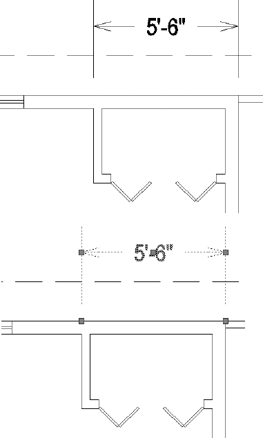
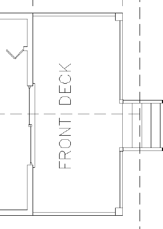
Pan and zoom to get a good view of the right side of the floor plan, including the front deck (see Figure 12.27).
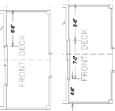
Click the Linear button, and then start a vertical dimension from the top of the right exterior wall.
Place the second point at the endpoint on the opening of the sliding door. Click to place the dimension between the wall and the FRONT DECK text. Adjust the location of the text if needed (see the left image of Figure 12.28).
Tip
AutoCAD can sometimes be conservative when deciding whether both text and arrows can fit between the extension lines. Try moving the text a bit toward one of the extension lines in one of the 4′−6″ dimensions and notice how the arrows move from outside the extension lines to inside.
Use the Continue command and grips to draw and edit the remaining two dimensions for the front of the cabin (see the right image of Figure 12.28).
Using a similar procedure, draw the vertical dimensions for the front deck, placing the dimensions to the right of the deck. Add a horizontal dimension showing the length of the stairway. When you're done, your dimensions should look like those in Figure 12.29.
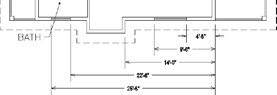
You place the rest of the horizontal and vertical dimensions using procedures similar to the one you used to complete the horizontal dimensions. Here is a summary of the steps:
Use the Linear and Continue commands to add horizontal dimensions to the bottom side of the building. Move the title and label text as required to display the dimensions clearly.
Add dimensions to the rear of the cabin and for the rear deck.
Dimension the roof.
Dimension the inside of the bathroom. After starting the Linear command, Press
The completed dimensions will be similar to Figure 12.30.
Save your drawing as
cabin12b.dwg.
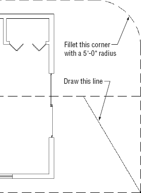
AutoCAD provides tools for placing radial and angular dimensions on the drawing and for placing linear dimensions that are neither vertical nor horizontal. You'll make some temporary changes to the cabin file that you just saved, so that you can explore these tools and then close the drawing without saving it:
Freeze the Dim1, Deck, Steps, and Text1 layers.
Use the Fillet command to fillet the top-right corner of the roof with a radius of 5′−0″ (1525 mm).
Start the Line command, and then pick the lower-right corner of the roof as the start point.
Activate the Nearest osnap, and pick a point on the roof's ridgeline. The right end of the cabin should look like Figure 12.31.
On the drop-down menu on the left side of the Dimensions panel are icons for Radius, Diameter, and Arc Length dimensions. They all operate the same way and are controlled by the same settings.
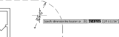
Follow these steps to place a radius dimension at the filleted corner, measuring the distance from the curve to the center point:
Click the Osnap button on the status bar to disable any running osnaps temporarily.

Note
Most of the commands used for dimensioning are prefaced with a dim when you enter them at the command line; that is, dim is part of the command name. For example, when you click the Radius button on the Dimension toolbar or choose Dimension

Click the inside filleted corner well above the midpoint. The radius dimension appears, and the text is attached to the cursor. Where you pick on the curve determines the angle of the radius dimension (see Figure 12.32).
Click to place the radius text in the dimension. The "R" prefix indicates that this is a radius dimension.
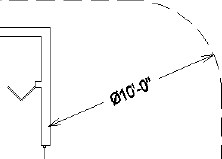
Similar to the radius dimension, a diameter dimension measures the distance from one side of a circle or arc, through the center point, to the other end. Follow these steps to place a diameter at the filleted corner:
Erase the radius dimension.

Click the inside filleted corner near the location where it meets the vertical wall. The diameter dimension appears and the text is attached to the cursor.
Click to place the radius text in the dimension. The Ø prefix indicates that this is a diameter dimension. Where you pick on the curve determines the angle of the radius dimension (see Figure 12.33).
An arc length dimension measures the length of an arc or polyline arc segment. As shown in Figure 12.34, an arc symbol, or cap, precedes the text to identify it as an arc length dimension. Follow these steps to place an arc length dimension at the filleted corner:
Tip
You can change the location of the arc length symbol, from in front of the text to over it, or eliminate it altogether in the Symbols and Arrows tab of the Modify Dimension style dialog box.
Erase the radius dimension.

Click anywhere on the arc at the filleted corner and the arc length dimension appears attached to the cursor.
Click to locate the dimension (see Figure 12.34).
Setting Up Parent and Child Dimensioning Styles
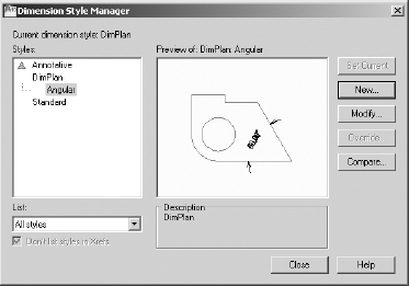
The DimPlan dimension style that you set up at the beginning of this chapter applies to all dimensions and is called the parent dimension style. You can change settings in this dimension style for particular types of dimensions, such as the radial type. This makes a child dimension style. The child version is based on the parent version, but it has a few settings that are different. In this way, all your dimensions will be made using the DimPlan dimension style, but radial dimensions will use a child version of the style. Once you create a child dimension style from the parent style, you refer to both styles by the same name and you call them a dimension style family. Follow these steps to set up a child dimension style for radial dimensions:
Click the Dimension Style button at the right end of the Dimensions panel to open the Dimension Style Manager dialog box.
With the parent style highlighted in the Styles list, click the New button to open the Create New Dimension Style dialog box.
Open the Use For drop-down list, select the type of dimensions for which you want to set up a child style, and then click the Continue button. The New Dimension Style dialog box opens and has the seven tabs you worked with earlier. Its title bar now includes the type of dimension you just identified, and the preview window shows a preview of that dimension type only.
Click the tabs and make the desired parameter changes.
Click OK to close the New Dimension Style dialog box.
In the Dimension Style Manager dialog box, notice the Styles list; the current dimension style now has a child style indented below it:
Click Close to close the Dimension Style Manager dialog box.
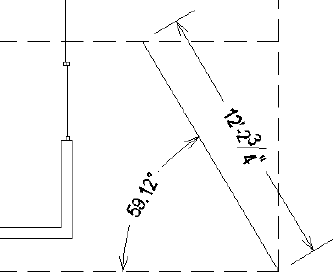
To become familiar with the aligned and angular dimension types, you'll experiment with the line you drew from the opposite corner of the roof in the previous exercise.
Aligned dimensions are linear dimensions that aren't horizontal or vertical. You place them in the same way that you place horizontal or vertical dimensions with the Linear command. You can also use the Baseline and Continue commands with aligned dimensions.
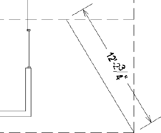
Use the Aligned command, which works just like the Linear dimension command, to dimension the line you drew at the beginning of this exercise. Follow these steps to add an aligned dimension:
Zoom in to the lower-right corner of the cabin roof.

Press
Pick the diagonal line. The dimension appears attached to the cursor.
Click to place the dimension. Your drawing should look similar to Figure 12.35.
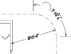
The angular dimension is the only basic dimension type that uses angles in the dimension text instead of linear measurements. Try making an angular dimension on your own. First turn off running osnaps.
Figure 12.36 show the angular dimension on the roof.
Ordinate dimensions are widely used by the mechanical and civil engineering professions and related trades. They differ from the kind of dimensioning you have been doing so far in this chapter in that ordinate dimensioning specifies x- and y-coordinate values for specific points in a drawing based on an absolute or relative Cartesian coordinate system, rather than on a distance between two points. This method is used to dimension centers of holes in sheet metal or machine parts and to locate surveying points on an area map.
You don't need ordinate dimensions in the cabin project, so you'll now go through a quick exercise in setting them up to dimension the holes in a steel plate. Doing so will give you a glimpse of the tools that AutoCAD provides for this type of work. (If you aren't interested in ordinate dimensioning, move on to the next section, "Using Leader Lines," to modify the dimensions you've already created for the cabin.)
Open a new drawing, and leave the units at the default of Decimal with a precision of four decimal places. Turn polar tracking on.
Set up a new text style, and set 0.125 as the height. Click Apply and then Close to make it the current text style.
Draw a rectangle using 0,0 as the first point and 6,−4 as the second.
Use Zoom To Extents, and then zoom out to see the area around the object. Turn off the UCS icon.
Somewhere in the upper-left quadrant of the rectangle, draw a circle with a radius of 0.35 units. Then, using Polar Tracking or Ortho mode, copy that circle once directly to the right, once directly below the original, and to two other locations that are not aligned with any other circle, so the configuration looks something like the top of Figure 12.37.
Set the Endpoint and Center osnaps to be running, and turn on Ortho mode.
What you are concerned with in ordinate dimensioning isn't how far the holes are from each other but how far the x- and y-coordinates of the centers of the holes are from a reference point on the plate. You'll use the upper-left corner of the plate as a reference point, or datum point, because it's positioned at the origin of the drawing, or at the 0,0 point.

Click the upper-left corner of the rectangular plate, and then move the cursor straight up above the point you picked. When you're about an inch above the plate, click again. This sets the first ordinate dimension (see the top left of Figure 12.37).
Press the spacebar to repeat the Dimordinate command, and then repeat step 8 for the four circles near the middle or upper portions of the plate, using their centers as points to snap to and aligning the ordinate dimensions by eye. The lower circle is in vertical alignment with the one above it, so it needs no horizontal dimension. Place an ordinate dimension on the upper-right corner of the plate to finish. Press the F8 key to toggle Ortho mode off if you need to jog an extension line. The result should look like the top right of Figure 12.37.
Repeat this procedure for the y-ordinate dimensions. Once again, ignore any circles that are in vertical alignment, but include the upper-left and lower-left corners of the plate (see the bottom of Figure 12.37).
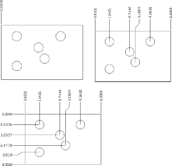
Figure 12.37. Placing the first ordinate dimension (top left), finishing up the x-coordinate dimensions (top right), and placing the y-coordinate dimensions (bottom)
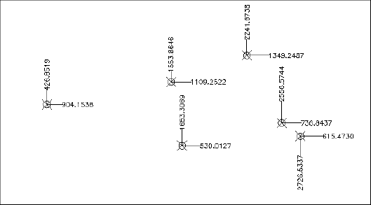
In civil engineering, ordinate dimensions are used almost the same way but displayed differently. A datum reference point is used, but the dimensions are displayed at each point. This is because the points are a set of surveying points spread randomly over a large area, and the datum or reference point might be miles away (see Figure 12.38).
When you change settings for a dimension style, dimensions created when that style was current automatically update to reflect the changes. You'll modify more dimensions in the next section.
You have been introduced to the basic types of dimensions—linear, radial, leader, and angular—and some auxiliary dimensions—baseline, continue, and aligned—that are special cases of the linear type. You can also use the baseline and continuous dimensions with angular dimensions.
You will use the Multileader command to draw an arrow to features in the drawing to add descriptive information. Multileaders are not part of the dimension family, and you can find them on the Multileaders panel. Before you create a leader, you need to create a multileader style:
You don't need to save the changes from the previous exercise so, if it's still open, close the
Cabin12b.dwgwithout saving it and then reopen the file.Click the Multileader Style Manager button at the right end of the Leaders panel's title bar.
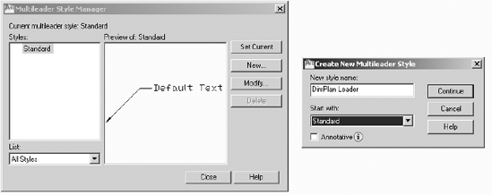
Click the New button in the Multileader Style Manager. In the Create New Mulitleader Style dialog box that opens, enter DimPlan Leader in the New Style Name text box and then click Continue (see Figure 12.39).
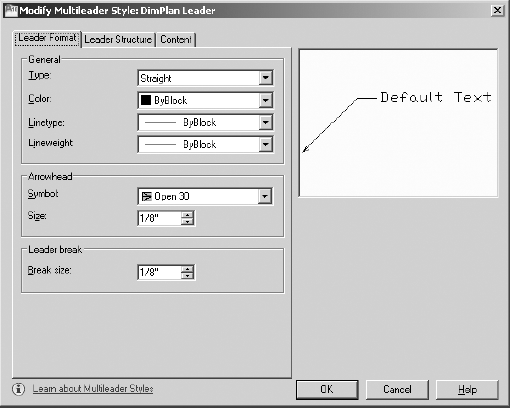
The Modify Multileader Style dialog opens (see Figure 12.40). This is where you define the leader properties. In the Leader Format tab, expand the Symbol drop-down list in the Arrowhead section, and choose Open 30. Set Size to 1/8″ (3.5).
Click the Leader Structure tab. The landing is the horizontal line at the end of the leader, just before the text. Make sure the Set Landing Distance option is checked, and then enter 3/16″ (0.36) in the text box.
In the Scale area, make sure the Specify Scale radio button is selected and then click in the text box and enter 64
Switch to the Content tab. Expand the Text Style drop-down list, choose Dim, and set the text height to 1/8″ (3.5).
In the Leader Connection area, set both the Left Attachment and Right Attachment options to Middle of Top Line. This places the middle of the top line of the leader text even with the landing.
Set the Landing Gap value to 1/8″ (3.5).
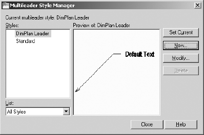
In the Multileader Style Manager, the DimPlan Leader style appears in the Styles list box (see Figure 12.41). Select it, click Set Current, and then click the Close button.
To add the leaders to the drawing, follow these steps:
Zoom in to the front deck.

Activate the Endpoint osnap, if necessary, and then click the top-right corner of the top-right deck post.
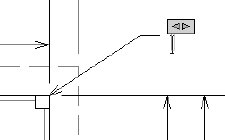
At the
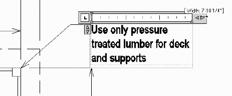
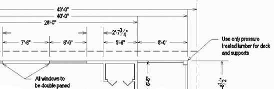
Specify leader landing location:prompt, click a point above and to the right of the deck. The Text Editor tab and panels replace the Annotate tab and panels in the Ribbon, and a flashing vertical cursor appears to the right of the landing, as shown in Figure 12.42.Enter Use only pressure treated lumber for deck and supports, and then drag the right arrow near the text to adjust the width of the multiline text object, as shown in Figure 12.43. Click a blank spot in the drawing area to complete the text and return to the Annotate tab.
Pan to the right so that you can see the two windows on the north side of the cabin.
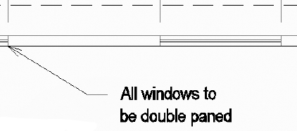
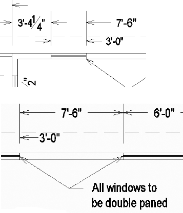
Add a leader that starts at the right edge of the 3′ (915 mm) window and then extends below and to the right. Enter All windows to be double paned at the text prompt, adjust the width of the text, and then click a blank spot in the drawing area (see Figure 12.44).

Note
AutoCAD may place the second leader on the right side of the text if it determines that the leader fits better there. If this happens, click the multileader to select it and then move the text to the right. The second leader will reposition itself to the left side of the text.
Reposition the text as necessary. Your drawing should look similar to Figure 12.45.
Save this drawing as
Cabin12c.dwg.
The final part of this chapter will be devoted to teaching you a few techniques for modifying dimensions.
You can use several commands and grips to modify dimensions, depending on the desired change. Specifically, you can do the following:
You can change the dimension text content.
You can move the dimension text relative to the dimension line.
You can move the dimension or extension lines.
You can change the dimension style settings for a dimension or a group of dimensions.
You can revise a dimension style.
The best way to understand how to modify dimensions is to try a few.
You can modify any aspect of the dimension text. You'll look at how to change the content first.
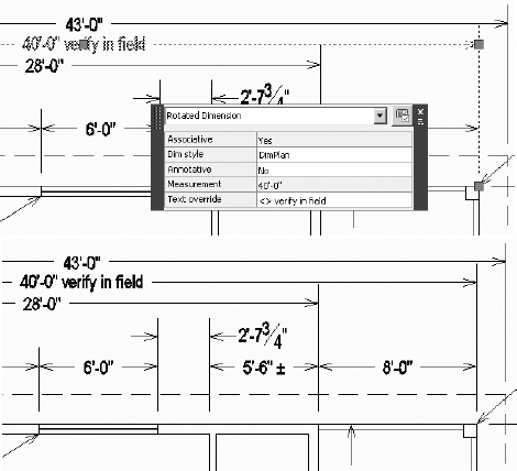
To change the content of text for one dimension, or to add text before or after the dimension, you can use the Properties or Quick Properties palette. You'll change the text in the horizontal dimensions for the cabin and walls using Quick Properties:
Zoom and pan until your view of the floor plan is similar to Figure 12.46.

Tip
The procedure shown here can also be done in the Text rollout of the Properties palette.
Highlight the Text Override field, and enter <> verify in field
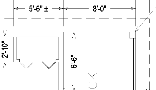
Press the Esc key, and then click the 5′−6″ (1670 mm) dimension, measuring the distance from the end of the cabin to the closet wall.
In the Text Override box, enter <> %%P
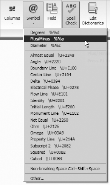
Unless you have memorized all the ASCII symbol codes, it might be easier to insert symbols into dimension text using the text editing tools command. To do this, choose Modify
You can use grips to move dimensions. You used grips to move the dimension lines when you were putting in the vertical and horizontal dimensions. This time, you'll move the dimension line and the text:
Zoom in to a view of the upper-left side of the floor plan until you have a view that includes the left window and the top of the rear deck and their dimensions.
Select the 3′−0″ (915 mm) window dimension. Its grips appear.
Click the grip on the right arrowhead to activate it.
Move the cursor down until the dimension text is just below the roofline. Click again to fix it there.
Click the grip that's on the text and, with polar tracking on, move the text to the right, outside of the extension line; then click to place it. Press Esc to deselect the dimension (see the top of Figure 12.49).
Select either of the leader lines pointing to the two windows. The leaders, landing, and leader text ghost and the grips appear.
Click the grip at the tip of the left leader, then move the grip to the end of the inner pane of the left window (see the bottom of Figure 12.49).
Click the grip at the tip of the right leader, and move the grip to the left end of the inner pane of the right window (also shown at the bottom of Figure 12.49).
You can suppress the left extension line with the Properties palette, which allows you to change a setting in the dimension style for one dimension without altering the style settings. Follow these steps:
Thaw the Headers layer.
Notice how the white (or black), left extension line for the 8′−0″ (2350 mm) dimension, measuring the width of the bath room, coincides with the header line. You could use the Draw Order tools to move the dimension behind the header, but that may still result in a visibly overlapping condition when the drawing is printed. In this case, you'll suppress the extension line, rendering it invisible.
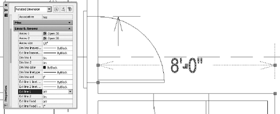
Double-click the 8′−0″ (2350 mm) dimension to open the Properties palette.
Scroll down to the Lines & Arrows rollout. If this section isn't open, click the arrow to the right.
Scroll down the list of settings in this section, and click Ext Line 1. Then click the down arrow to the right to open the drop-down list. Click Off. This suppresses the left extension line of the dimension (see Figure 12.50).
Close the Properties palette. Press Esc to deselect the dimension.
To illustrate how dimension overrides work, you suppressed an extension line without having to alter the dimension style. Extension lines are usually the thinnest lines in a drawing. It's usually not critical that they be suppressed if they coincide with other lines, because the other lines will overwrite them in a print.
However, in this example, the left extension line of the 8′−0″ (2350 mm) dimension for the bathroom dimension coincides with the line representing the header of the back door. If the Headers layer is turned off or frozen, you will have to unsuppress the extension line of this dimension so that it will be visible spanning the door opening. Also, if you dimension to a noncontinuous line, such as a hidden line, use the dimension style override features to assign special linetypes to extension lines. In the practice exercises at the end of this chapter, you'll get a chance to learn how to incorporate center lines into your dimensions.
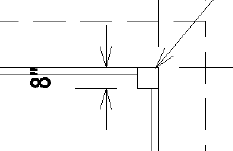
When you have to dimension distances so short that both the text and the arrows can't fit between the extension lines, a dimension style setting determines where they are placed. To see how this works, you'll add dimensions to the deck dimensioning the widths of the handrails and posts as well as the thickness of an interior wall. Then make a change in the Fit tab to alter the DimPlan dimension style to change where it places text that doesn't fit between the extension lines:
Zoom and pan to a view of the upper portion of the front deck so that the horizontal dimensions above the floor plan are visible (see Figure 12.51).
Activate the running osnaps if necessary, click the Linear button, and pick the upper-left corner of the deck post. Then pick the lower-left corner of the same deck post. Place the dimension line about 2′ (610 mm) to the left of the deck post. The 8″ (204 mm) dimension is placed even farther to the left of the point you selected (see Figure 12.52).
Tip
Several of the dimensioning commands are also available on the Annotation panel under the Home tab.
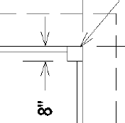
Open the Dimension Style Manager dialog box, click the Modify button, and then, in the Modify Dimension Style dialog box, click the Fit tab.
In the Text Placement area, select the Beside The Dimension Line radio button (see Figure 12.53); click OK and then Close to shut both dialog boxes.
The dimension changes to reflect the modification to the style (see Figure 12.54). This is a global change that will affect all future dimensions.
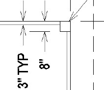
Add another dimension measuring the width of the horizontal handrail, and add the text TYP after the dimension text, as shown in Figure 12.55. Refer to the "Modifying Dimension Text" section if you need a refresher.
Make any adjustments necessary to make the drawing readable, and then save the drawing as
Cabin12d.dwg.
This concludes the exercises for dimensions in this chapter. Working successfully with dimensions in your drawing requires an investment of time to become familiar with the commands and settings that control how dimensions appear, how they are placed in the drawing, and how they are modified. The exercises in this chapter have led you through the basics of the dimensioning process. For a more in-depth discussion of dimensions, you can refer to Mastering AutoCAD 2010 and AutoCAD LT 2010 by George Omura (Wiley, 2009).
The next chapter will introduce you to external references, a tool for viewing a drawing from within another drawing.
In the first practice exercise, you'll get a chance to use the dimensioning tools that you just learned. After that is a short exercise that shows a technique for incorporating center lines into dimensions.
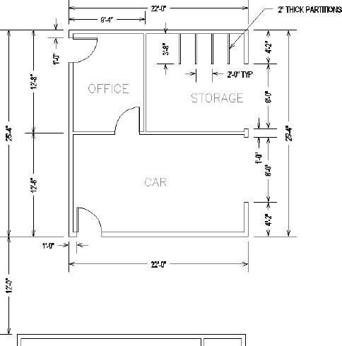
Try dimensioning the garage addition to the cabin that was shown at the end of Chapter 4 (Cabin04c-addon). Use the same techniques and standards of dimensioning that you used in this chapter to dimension the cabin; use the DimPlan dimension style you set up and used in this chapter.
Open
Cabin04c-addon.dwg. Then use the DesignCenter to bring over the DimPlan dimension style, the Dim text style, the DimPlan Leader multileader style, and the Dim1 layer.Dimension to the outside edges of exterior walls, the edges of the openings, and the center lines of interior walls.
Drag a Room_Info block and a room label from the cabin drawing into the garage drawing, and then copy and modify them as required.
If the leader does not display properly, check the Overall Scale value in the Properties panel and make sure it is set to 64 (70). When you're done, the drawing should look similar to Figure 12.56.
When you're finished, save this drawing as
Cabin12d-addon.dwg.
This exercise will show you how to use center lines as replacements for extension lines in dimensions. I'll use as many of the default settings for AutoCAD as I can to give you a look at what out-of-the-box, or vanilla, AutoCAD looks like; that is, how drawings look if you use the default settings for text styles, dimension styles, units, and so forth. The drawing you'll make is similar to the one you made in Chapter 2, but you know so much more now:
Choose File
Start the Rectangle command, and click a point in the lower-left quadrant of the drawing area. For the second point, enter @6,2
Turn off the UCS icon, use Zoom To Extents, and then zoom out a bit. Pan to move the new rectangle down a little (see Figure 12.57).

You want to dimension from the upper-left corner of the rectangle to the center of the upper horizontal line and then to the upper-right corner. You'll select the Dimension command from the menu bar and use the default dimension settings:
Create a new layer called Dim, accept the White color, and make Dim current. Set the Endpoint and Midpoint osnaps to be running, and then click the Linear button in the Dimensions panel or in the Annotation panel under the Home tab. Click the upper-left corner of the rectangle, and then click the midpoint of the upper horizontal line of the rectangle. Drag the dimension line up to a point about one unit above the upper line of the rectangle, and click. This places the first dimension.
Click the dimension to make grips appear. Click the grip that is at the midpoint of the upper horizontal line of the rectangle, and with polar tracking on, drag it down to a point below the rectangle. Press Esc to deselect the dimension.
Click the Continue button, and select the upper-right corner of the rectangle. Doing so places the second dimension. Press Esc to end the command.
On the Properties panel, open the Linetype drop-down list and select Other. In the Linetype Manager dialog box, click the Load button.
In the Load Or Reload Linetypes dialog box, scroll down, find and click Center2, and then click OK. The Center2 linetype now appears in the Linetype Manager dialog box. Click OK.
Double-click the left dimension to open the Properties palette. In the Lines & Arrows rollout, click Ext Line 2 Linetype. Open the drop-down list, and select Center2. Press Esc to deselect the dimension.
Select the right dimension. On the Properties palette, return to the Lines & Arrows rollout, and click Ext Line 1 Linetype. Open the drop-down list, and select Center2. Press Esc to close the Properties palette.
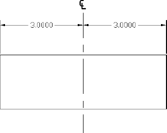
Now there is a center line through the rectangle that's part of the dimensions. As a final touch, you'll put a center line symbol at the top of the center line by using the MText command:
Start the Multiline Text command, and make a small defining window somewhere in a blank portion of the drawing area.
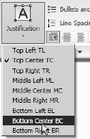
Right-click the drawing area and select Symbol in the context menu that appears, then select Center Line. A center line symbol now appears in the Multiline Text editor. Highlight it, and change its height from 0.2000 to 0.4000 in the Text Height text box in the Text Style panel, as shown in Figure 12.58.


Click the center line symbol to activate the grips. Click the lower-middle grip, and then click the upper end of the center line. This locates the symbol properly.
Turn off running osnaps, be sure polar tracking is on, and click the same grip you did in the previous step. Move the symbol up slightly to create a space between it and the center line (see Figure 12.60).
This completes the exercise. You can save the drawing if you wish.
Use the skills you've learned in this chapter to do the following:
Set up a dimension style for your own use.
Dimension a drawing as you would in your own profession or trade.
Dimension any of the other drawings offered in previous chapters, such as the block, the gasket, or the parking lot.
Add dimensions to the cabin elevations.