8. Advanced Programming
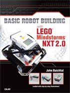
In this chapter, we learn a bit more about Mindstorms programming and how it works. First and foremost, we explore data wires, NXT-G’s on-screen representation of the flow of data (see Figure 8.1). When one programming block needs to send information to another block, it uses data wires.
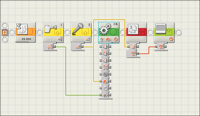
Figure 8.1. Look complicated? Let’s learn more about programming.
Wires are the key to turning an otherwise blah program into a sophisticated and responsive one that can pull in data from its sensors and use that data to adjust the behaviors of various blocks. Learning about wires is one of the keys to advanced programming!
Tip: There’s Wire...and There’s Wire
There’s a good chance you’re puzzled about the use of the word wire in this book. There are physical wires, actual wires that you can touch that plug into the NXT and transmit electricity and data. Then there are data wires. These are only on the screen and illustrate the flow of data from one block to another. Both are called wires in Mindstorms circles, so be aware of the context when the term crops up. If we’re talking about the programming world, then chances are we’re talking about data wires rather than physical ones.
Data Wires
In the Mindstorms programming world, wires regulate all the flow of data throughout the program. What if you want to have the reading from the Light sensor regulate how far your robot travels? Wires send data from one block to the other and make it happen. There are four kinds of data wires, described next.
Green Wires
The green wires carry Logic data, which is Mindstorms parlance for things that are either true or false. Note that some blocks refer to “true” or “false” as “yes” or “no,” but for purposes of simplicity we’re just going to use “true” or “false.” Put simply, there are literally only two possible types of data transmitted by a Logic wire: absolutely true and absolutely false. Here’s an example: A button is either pressed or not pressed. If it’s pressed, the program returns a true response; if it’s not pressed, the result is false. We see this in action in Figure 8.2.
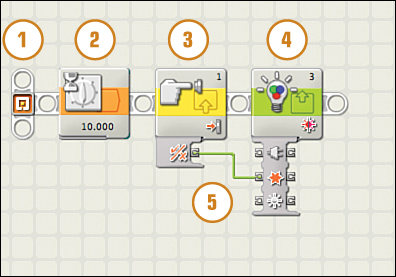
Figure 8.2. Green wires carry Logic data, which represent a statement that can be either true/yes or false/no.
1. The program begins with the starting point. Every program begins there and works its way to the right, following each block in sequence.
2. The Wait block pauses the program for 10 seconds. After that time has elapsed, the program continues.
3. The Touch Sensor block is the next in line. If the button is pressed when this block executes, a Logic signal is sent along a green data wire to the Color Lamp block.
4. The Color Lamp block turns the color sensor into a light. The green Logic wire delivers either a true or false signal. In the former case, the light comes on! If the button isn’t pressed, a false signal is sent and the light remains dark.
5. This marks the path of the green data wire as it travels from the Logic plug of the Touch Sensor block’s data hub to the Color Lamp’s hub.
Yellow Wires
Yellow wires carry Number data. What the heck is this? Is Number data any old number? Well, sort of. It’s actually kind of tricky. Let’s break it down:
• An Ultrasonic sensor’s reading is a Number because the sensor generates a number based on the robot’s distance to an object.
• A Touch sensor’s output isn’t a Number because it creates only a yes or no, which is called Logic data in the Mindstorms world.
• Number data can be manipulated with math and can change a motor’s or sensor’s settings. In Figure 8.3, a Rotation Sensor block returns Number data showing the degrees of rotation, and sends that data along a yellow data wire to the Motor block, which alter’s the motor’s duration (how long it turns) accordingly.

Figure 8.3. Yellow wires send Number data, which is just what it sounds like!
Orange Wires
Text data is transmitted through orange wires. Text differs from Number data in that it’s an actual string of text, such as a sentence or name. An example of this could be the output of a Text block, which can’t output Number or Logic data. You could spell out a sentence with Text data, but you couldn’t do math with it or make the motors turn a certain number of rotations.
Text data is unique in that it is the only kind of data that can be displayed on the NXT brick’s screen. If you wanted to display a sensor’s reading, you’d first have to convert the reading from Number data to Text data using a special block—the Number to Text block. Figure 8.4 shows an example of how to use the Number to Text block.

Figure 8.4. Text data, carried by orange wires, consists of strings of letters, numbers, and punctuation marks.
1. For example, look at the reading from your Light Sensor. The reading is output through a yellow wire as Number data.
2. The yellow wire begins with the Intensity port of the Light Sensor block’s data hub and travels to the number port of the Number to Text block.
3. The Number to Text block converts Number data to Text data, not surprisingly! Data converted this way can then be displayed on the NXT brick’s screen.
4. The orange Text wire travels from the Text output plug of the Number to Text block to the input data plug of the Display block.
5. The Display block accepts the Text data and displays it on the screen!
Gray Wires
If you see a gray wire on the NXT screen, that means the wire is busted and won’t transmit data. There can be a number of reasons why the wire isn’t working. If you try to connect two mismatched plugs—a Number plug and a Text plug, for instance—the wire will turn gray, indicating that the connection isn’t going to work. Another example might be a broken string of wires where data isn’t supplied to one block, so it can’t transmit the data to the next. In Figure 8.5, we see a wire string between two output Logic plugs of two sensors. Because two output plugs can’t be connected, a gray wire is the result. Gray wires in your program will result in a failed download, so you must make sure your wires are in order if you want your robot to work.

Figure 8.5. Uh oh! A gray wire indicates a broken connection.
Connecting Wires
The first step to connecting two blocks with wires is to open their data hubs. Some blocks automatically pop out their hubs when placed on a sequence beam. The tricky thing is that they don’t always pop out all the way. If you don’t see the plug you want, click on the tab to extend it all the way. Clicking on the tab again after you’ve added wires will hide all the unused plugs.
Next, click on the output data plug of the type of connection you want to make. Remember, inputs are on the left, and outputs are on the right. Then, while holding down the mouse button, “draw” a line to the input plug of the block you want to connect to (see Figure 8.6). If you did it right, the wire will be colored orange, green, or yellow. If you messed it up, the wire will be gray. If you change your mind and want to delete the wire, click on the input plug the wire leads to.
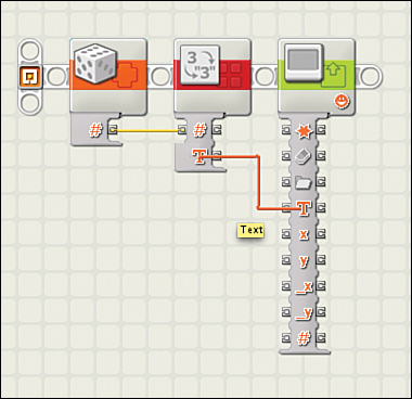
Figure 8.6. Want to connect two blocks with a wire? Just click and draw it with your mouse pointer.
Additional Blocks
Although we covered a bunch of blocks in previous chapters, there are a few more yet to discuss. You won’t use these blocks in every program, but you’ll be glad to have access to them when you finally need them!
Variable Block
In the programming world, a variable is a piece of data that can be modified during the operation of the program (see Figure 8.7). For instance, a Light sensor could tell you whether the room was light or dark, and the result would be saved within the Variable block so that the robot would always know. Variables can be either Logic, Number, or Text, and the block can be set to read or write the variable.
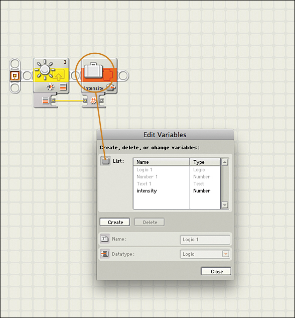
Figure 8.7. The suitcase icon represents a variable—in this case, a Number variable.
When modifying a variable, you set the block to “write.” When you want to access the value stored, you set the block to read and whatever data is stored may be accessed by another block.
Constant Block
The Constant block creates a Number, string of Text, or a true/false Logic statement that when placed into a program, never changes. That constant can be accessed through data wires as needed and can be given its own name so you can easily reference it.
You use constants much the same way as you’d use a variable, except that once defined, a constant can’t be changed during the course of the program. In the example in Figure 8.8, a Logic constant activates a light.
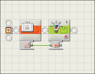
Figure 8.8. Unlike a variable, a constant never changes.
Random Block
A Random block generates a random number between 0 and 100 (the default) or any other range smaller than that, every time you launch the program. For instance, you could make the range 1–20 if you wanted, or 15–75. In the example shown in Figure 8.9, a Random block generates a number, which sets the duration of a Motor block. Changing the range of the random number ensures that the motor doesn’t roll too far!

Figure 8.9. A Random block creates a random number that can be used to add the unpredictable to your program.
Keep Alive Block
Although normally you can set the amount of time before the NXT brick falls asleep directly from the NXT menus, the Keep Alive block lets you renew that timer. For instance, you could have the brick stay awake during a longer program and then fall asleep when done.
If you select the Keep Alive block, you’ll immediately notice that the configuration panel is black; there are no settings to change. The way it works is that whenever the program launches the Keep Alive block, the NXT’s built-in sleep timer resets. So, if you set the NXT to fall asleep after five minutes, then every time the Keep Alive block is run, that five-minute timer starts over at the beginning. In other words, if you want to keep your program running indefinitely, include a Keep Alive block in a loop as shown in Figure 8.10.
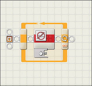
Figure 8.10. The Keep Alive block inside a loop keeps your NXT brick awake.
Light Sensor Block
The Light Sensor block uses a Light sensor to detect ambient light levels, sending either a numeric light reading or a true/false via a data wire. As shown in Figure 8.11, the Light sensor returns a “true” value” if reading is a 50 or higher. The Logic wire connecting the Light Sensor block to a Motor block activates the motor’s power and it starts moving!
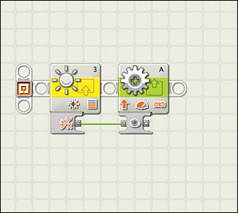
Figure 8.11. The Light Sensor block takes information from the sensor and shares it with other program blocks.
Rotation Sensor Block
The Rotation Sensor block takes data from a motor’s encoder—the widget inside the motor that tells the NXT how far and how fast the hub turns—and returns either the number of rotations or the number of degrees made by the motor to the program, which compares it against a preset value. The example in Figure 8.12 shows how you could control the turns of a motor’s hub with another motor; the block detects the rotation of the first motor and instructs the second motor to mirror it.
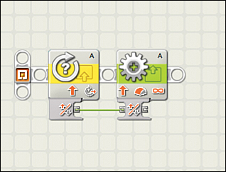
Figure 8.12. How far did that motor hub turn? The Rotation Sensor block can tell you.
Display Block
The Display block controls the NXT brick’s screen, allowing you to use the display as part of your robot. You can set it to show text, or you can also have it display a drawing like a smily face. Figure 8.13 shows how you could set the Display block to display the reading of an Ultrasonic sensor, using the Number to Text block to convert the Number data the sensor outputs into the Text data the Display block can handle.
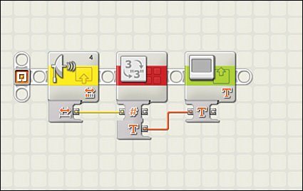
Figure 8.13. The Display block controls the NXT brick’s LCD screen.
Bluetooth Block
Multiple Bluetooth blocks manage the wireless communications of your robot. The Bluetooth Connection block (the leftmost block in Figure 8.14) activates a wireless connection between two NXT bricks, providing the two have previously connected and appear on each other’s contact list. The Send Message (middle block) and Receive Message (rightmost) blocks control the stream of data—Logic, Text, or Number—that can be transmitted between NXT bricks via Bluetooth. Note that that Figure 8.14 doesn’t actually show a viable program; I just put all three blocks on a beam so you could see them.
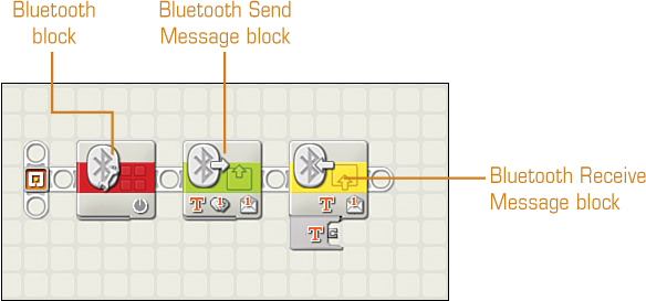
Figure 8.14. Mindstorms’ Bluetooth capability is controlled by these three blocks.
Logic Block
As we’ve already discussed, Logic data can be either true or false. The Logic block manages inputs from up to two sources of Logic data and then sends out a Logic signal to the next block. In the case of Figure 8.15, two touch sensors trigger a Color Lamp block; the Logic block looks for both buttons to be pressed simultaneously before it triggers the lamp.
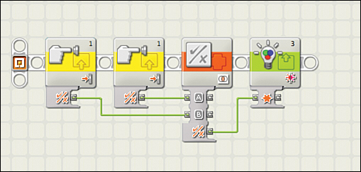
Figure 8.15. The Logic block accepts data from two input plugs and outputs a yes/no.
Tip: Logic from Two Places
The Logic block works with the Mindstorms Logic function, which governs conditions that are either true or false. The cool thing is that it can accept Logic data from two data wires, allowing it to reference both when making a decision. For instance, it could look to see if Data A is true while Data B is false, or both are true, or both are false.
Creating Your Own Blocks
One of the most intriguing aspects of NXT-G programming is the possibility of combining one or more blocks into a single customized block. The way this works is that you can grab a series of programming blocks and their data wires and combine their functionality into a single block, called a My Block. If you’re planning on using this new block a lot, you can even save it and drop it into all of your programs.
Here’s how it works: Say you want to display your light sensor readings on the NXT brick’s screen, which would ordinarily take three blocks—a Light Sensor block sending data to a Number to Text block and then to a Display block. The Number to Text block takes the Number data from the sensor and converts it to Text; the Display block then shows the text on its screen. By combining these three blocks into a single My Block that has already been configured the way you like, you can save yourself a lot of time!
Here’s how you do it:
1. Lay Out Your Blocks—First, arrange the blocks just as you would do in a normal Mindstorms program with all the data wires set up the way you want. Click and drag to select all the blocks you want to turn into a My Block (see Figure 8.16). It doesn’t have to be every block in the program!
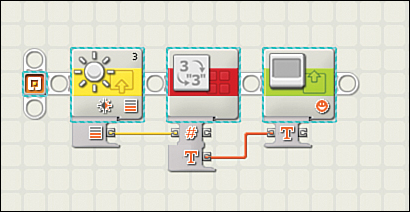
Figure 8.16. To create a My Block, first start with the snippet of program you want to turn into a block.
2. Launch Create My Block—Next, select Create My Block from the Edit menu. Your blocks appear in a pop-up window labeled My Block Builder (see Figure 8.17). This view is completely editable, so if you need to make changes, or you accidentally added on or left off a block, you can fix the problem in this view. Now you can edit your My Block any time you want! Note that editing a My Block edits it for all uses of that block, so if you edit it to draw from Port 1 instead of Port 3, forever after that block will pull data from Port 1. If you want to pull data from two sensors, you need two separate versions of the My Block. You’ll also need to come up with a name for your block; choose one that describes precisely what the block does.

Figure 8.17. Launching the Create My Block option brings your blocks into a separate window.
3. Edit the Icon—After you set the custom block’s program, click on Next and you are able to edit its icon (see Figure 8.18). This simple process involves adding one of a wide assortment of icons to a teal-colored block. When you’re done, click Finish and you return to your original program (see Figure 8.19), but with your new block in place of the code you selected. It’s slick!
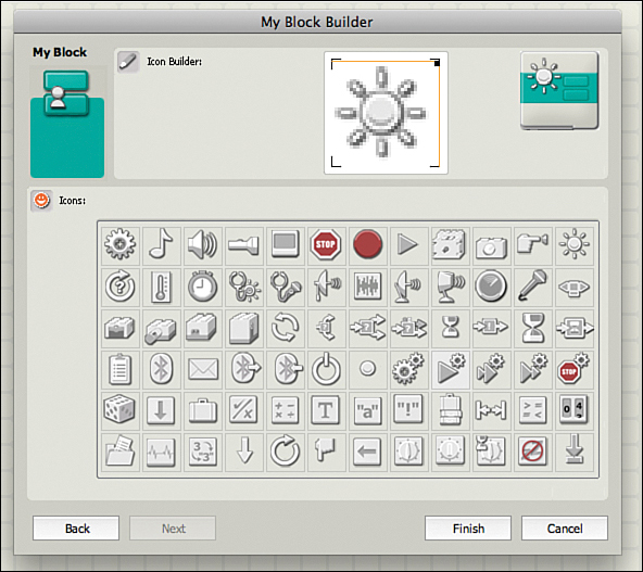
Figure 8.18. You can customize your icon to make your block more recognizable.

Figure 8.19. The end result of the process is a custom block that appears in your program!
The Next Chapter
In Chapter 9, “Project: Rebounder,” we build our third and final robot, the Rebounder. This cool tank-treaded roller uses a couple of cool programming tricks that will keep you thinking about NXT-G! Even better, you get to create a robot that interacts with its environment.