
C H A P T E R 4
Inputs
In the context of the ADK board, inputs are pins and connectors on the board with which you can receive data or measurements. Although the common USB-type connectors are technically also inputs, this chapter will only concentrate on the inputs with which you can take measurements or detect digital state changes. The inputs in that sense are the pins of the ADK board.
The majority of the pins on an ADK board are capable of being used as input pins. You remember that digital pins can be configured to work as outputs and inputs. Digital pins are configured as input pins by default. You can set them into input mode by using the pinMode method, but you don’t necessarily need to.
Additionally, an ADK board has dedicated analog input pins. With analog input pins you can measure changes in the applied voltage on those pins. The measured analog voltage is mapped to a digital representation you can process in your code.
Both input pin types and their use cases are described in the following two projects.
Project 3: Reading the State of a Button
In this project you will learn how the digital input pins on the ADK board can be used to detect the state of a button or a switch. For additional hardware you will need a button or a switch and a resistor. You can use a button or a switch in this project because they basically work the same way. Both components can be used to close or open a circuit. You will write an Arduino sketch that reads the current state of a button and transmits the state change to an Android application. The Android application receiving the state change will propagate the change in a TextView and your Android device's vibrator will be triggered to vibrate whenever the button is pressed.
The Parts
You already know most of the parts for this project by now. However, I will explain the principle of a button or switch, the use of a so-called pull-up resistor, and the use of a digital pin configured as an input pin. You will need the following hardware in this project (shown in Figure 4-1):
- ADK board
- Breadboard
- Button or switch
- 10kΩ pull-up resistor
- Some wires

Figure 4-1. Project 3 parts (ADK board, breadboard, resistor, button, wires)
Button or Switch
A button or a switch is a component used to control the state of a circuit. A circuit can be either closed, which means that the power source has a return path, or it can be open, which means that the circuit's return path is blocked or not connected to the circuit. To achieve the change from an open circuit to a closed one, a button or a switch is used. In its ON state, a button or switch ideally has no voltage drop across itself and no current-limiting properties. In its OFF state, a button or switch ideally has no voltage limit and an infinite resistance value. In a simple circuit diagram, a closed circuit would look like the one shown in Figure 4-2.
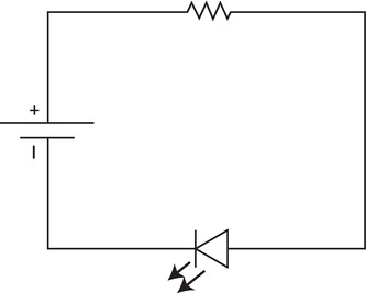
As you can see, the power can flow through the circuit's components to its return path. If you connect a switch or a button to that circuit you can control whether the circuit should be open or closed. By pressing the button or switching the switch to its ON position, you close the circuit so that power can flow through the circuit. If you release the button or switch the switch back to its OFF position, you disconnect the circuit, thus leaving it open. The circuit diagram symbol for a button or a switch is displayed as an open part in the circuit. The symbol for a switch can be seen in the circuit diagram in Figure 4-3.

Figure 4-3. Circuit with switch
Buttons and switches come in numerous types and sizes. Typical buttons can be push buttons, which you need to press and hold to close a circuit and release to open a circuit, or they can be toggle buttons, which reside in their current state after being pushed. Switches also have several shapes and application types, but the most common are the well known ON/OFF switch, which defines two states, and the toggle switch, which can switch between many states (see Figure 4-4).

Figure 4-4. Buttons and switches
Pull-up Resistor
You already used a resistor to limit the current in a circuit. In this project you will use a resistor in combination with a button or switch to pull the input pin to either LOW (0V) or HIGH (5V). This can be achieved by a special circuit setup.
There are certain situations in which you would want the input pin to be in a defined state. So, for example, when a digital pin is configured as an input and no component is connected to it you will still measure a voltage fluctuation. Those fluctuations are a result of external signals or other electrical disturbances. The voltage measured on the pin will be anywhere between 0V and 5V, which causes a continuous change in the digital readings of the pin state (LOW/HIGH). To eliminate those disturbances you will pull the voltage on that input pin up. In this kind of use case the resistor is called a pull-up resistor.
The pull-up resistor has to be placed between the voltage source and the input pin within the circuit. The button or switch is placed between the input pin and ground. A simple schematic for this setup looks like that shown in Figure 4-5.

Figure 4-5. Pull-up resistor circuit
An easy explanation of what happens here is that if the switch or the button is not pressed, the input is only connected to Vcc (5V), the line is pulled up, and the input is set to HIGH. When the switch or the button is pressed and the input is connected to Vcc and GND (0V), the current flow has more resistance at the 10kΩ resistor than at the switch or button, which has a very low resistance (usually way below 1Ω). In this case the input is set to LOW as the connection to GND is stronger than to Vcc.
The high-valued resistor is also needed to limit the overall current flow in the circuit. If you press the switch or button you directly connect Vcc to GND. Without a high value resistor you would let too much current flow directly to GND and you would cause a short circuit. The high current flow would cause heat to build up which, most of the time, will damage your components permanently.
ADK Board
You have already worked with the digital pins of the ADK board configured as output pins. For this project you will use the pins in their input mode. By using the digital pins as input pins you have the capability of measuring digital signals: a digital HIGH expresses a voltage of around 5V across the input pin, while a digital LOW is somewhere close to 0V. You have already learned that pull-up resistors can be used to stabilize the input pin so that it isn't influenced by disturbances by steadily pulling the pin up to the supply voltage of 5V. One specialty of the ADK boards is that the embedded ATmega chip has integrated pull-up resistors that can be activated by code. To activate an integrated pull-up resistor you only have to set the pin to input mode and set it to HIGH.
pinMode(pin, INPUT);           // set digital pin to input mode

digitalWrite(pin, HIGH);       // turn on pullup resistor for pin
I do not recommend using this technique in this project, however, so that you can learn the fundamentals of pull-up resistors firsthand. If you have no high-valued resistor at hand you can still change this project's code as shown above to activate the internal pull-up resistors. Note that you only have to use the pinMode method to define an input pin if it was used as an output pin before in the code. Per default, all digital pins are configured to act as inputs, so you won't have to explicitly set the pinMode if the pin is only used as an input the entire time.
The Setup
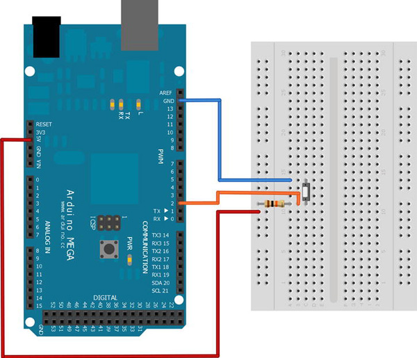
You have just learned that you need to connect your digital input pin which you want to use to a pull-up resistor circuit. You can see in Figure 4-6 that the +5V Vcc pin of the ADK board has to be connected to one lead of the 10kΩ pull-up resistor. The other lead is connected to the digital input pin 2. The digital pin 2 also connects to one lead of the switch or button. The opposite lead is connected to ground. It's as easy as that. With this setup you pull the input pin up to 5V when the button or switch is not pressed, causing the digital input pin to measure a digital HIGH. If the button or switch is now pressed, the digital input pin is pulled down to GND, causing the input to measure a digital LOW.
The Software
As described in the project description at the beginning of the chapter, you will write an Arduino sketch that continuously monitors the state of a digital input pin. Each time the pin changes its state from HIGH to LOW, or vice versa, you will send a message to the connected Android device. The Android application will listen to incoming state changes and it will show the current state in a TextView. Additionally, the vibrator of the Android device will be activated as long as the button is pressed.
The Arduino Sketch
As before, the Arduino sketch implementation is very straightforward. Have a look at Listing 4-1 and I will explain the details afterward.
Listing 4-1. Project 3: Arduino Sketch
#include <Max3421e.h>

#include <Usb.h>

#include <AndroidAccessory.h>


#define COMMAND_BUTTON 0x1

#define TARGET_BUTTON 0x1

#define VALUE_ON 0x1

#define VALUE_OFF 0x0

#define INPUT_PIN 2


AndroidAccessory acc("Manufacturer",

                     "Model",

                     "Description",

                     "Version",

                     "URI",

                     "Serial");


byte sntmsg[3];

int lastButtonState;

int currentButtonState;


void setup() {

  Serial.begin(19200);

  acc.powerOn();

  sntmsg[0] = COMMAND_BUTTON;

  sntmsg[1] = TARGET_BUTTON;

}


void loop() {

  if (acc.isConnected()) {

    currentButtonState = digitalRead(INPUT_PIN);

    if(currentButtonState != lastButtonState) {

      if(currentButtonState == LOW) {

        sntmsg[2] = VALUE_ON;

      } else {

        sntmsg[2] = VALUE_OFF;

      }

      acc.write(sntmsg, 3);

      lastButtonState = currentButtonState;

    }

    delay(100);

  }

}
The first thing to do here is to define some new message bytes for the button state message.
#define COMMAND_BUTTON 0x1

#define TARGET_BUTTON 0x1

#define VALUE_ON 0x1

#define VALUE_OFF 0x0

#define INPUT_PIN 2
Since the first two bytes of your message won't change, you can already set them in your setup method.
sntmsg[0] = COMMAND_BUTTON;

sntmsg[1] = TARGET_BUTTON;
Note that it is not necessary to call the pinMode method within the setup method because the digital pin is an input pin per default.
The first new method here is the digitalRead method, which measures the applied voltage on an input pin and translates it to two possible digital states, HIGH or LOW. The only parameter that is supplied to that method is the pin, which should be read.
currentButtonState = digitalRead(INPUT_PIN);
The next thing you see is that the current state is compared to the previous one so that a message is only sent to the Android device if the state has changed.
if(currentButtonState != lastButtonState) {

  if(currentButtonState == LOW) {

    sntmsg[2] = VALUE_ON;

  } else {

    sntmsg[2] = VALUE_OFF;

  }

  acc.write(sntmsg, 3);

  lastButtonState = currentButtonState;

}
Now let's have a look at the Android application.
The Android Application
The Android application for this project introduces no new UI element. You will visualize the state change of the button or switch with the help of the already known TextView. However, you will be learning how to call system services to address certain system or hardware features. For this project the vibrator service of the Android device will be responsible for controlling the vibrator motor in the device. First, have a look at the code in Listing 4-2. I will explain the new functionalities afterward. Again, the already known code parts that haven't changed are shortened so that you can focus on the important parts.
Listing 4-2. Project 3: ProjectThreeActivity.java
package project.three.adk;


import …;
public class ProjectThreeActivity extends Activity {


    …


    private static final byte COMMAND_BUTTON = 0x1;

    private static final byte TARGET_BUTTON = 0x1;

    private static final byte VALUE_ON = 0x1;

    private static final byte VALUE_OFF = 0x0;


    private static final String BUTTON_PRESSED_TEXT = "The Button is pressed!";

    private static final String BUTTON_NOT_PRESSED_TEXT = "The Button is not pressed!";


    private TextView buttonStateTextView;


    private Vibrator vibrator;

    private boolean isVibrating;


    @Override

    public void onCreate(Bundle savedInstanceState) {

        super.onCreate(savedInstanceState);


        …


        setContentView(R.layout.main);

        buttonStateTextView = (TextView) findViewById(R.id.button_state_text_view);


        vibrator = ((Vibrator) getSystemService(VIBRATOR_SERVICE));

    }


    @Override

    public void onResume() {

        super.onResume();

        …

    }


    @Override

    public void onPause() {

        super.onPause();

        closeAccessory();

        stopVibrate();

    }


    @Override

    public void onDestroy() {

        super.onDestroy();

        unregisterReceiver(mUsbReceiver);

    }


    private final BroadcastReceiver mUsbReceiver = new BroadcastReceiver() {

        @Override

        public void onReceive(Context context, Intent intent) {
            …

        }

    };


    private void openAccessory(UsbAccessory accessory) {

        mFileDescriptor = mUsbManager.openAccessory(accessory);

        if (mFileDescriptor != null) {

            mAccessory = accessory;

            FileDescriptor fd = mFileDescriptor.getFileDescriptor();

            mInputStream = new FileInputStream(fd);

            mOutputStream = new FileOutputStream(fd);

            Thread thread = new Thread(null, commRunnable, TAG);

            thread.start();

            Log.d(TAG, "accessory opened");

        } else {

            Log.d(TAG, "accessory open fail");

        }

    }


    private void closeAccessory() {

        …

    }


    Runnable commRunnable = new Runnable() {


        @Override

        public void run() {

            int ret = 0;

            final byte[] buffer = new byte[3];


            while (ret >= 0) {

                try {

                    ret = mInputStream.read(buffer);

                } catch (IOException e) {

                    break;

                }


                switch (buffer[0]) {

                case COMMAND_BUTTON:


                    if(buffer[1] == TARGET_BUTTON) {

                        if(buffer[2] == VALUE_ON) {

                            startVibrate();

                        } else if(buffer[2] == VALUE_OFF){

                            stopVibrate();

                        }

                        runOnUiThread(new Runnable() {


                            @Override

                            public void run() {
                                buttonStateTextView.setText(buffer[2] == VALUE_ON ?

                                    BUTTON_PRESSED_TEXT : BUTTON_NOT_PRESSED_TEXT);

                            }

                        });

                    }

                    break;


                default:

                    Log.d(TAG, "unknown msg: " + buffer[0]);


                    break;

                }

            }

        }

    };


    public void startVibrate() {

        if(vibrator != null && !isVibrating) {

            isVibrating = true;

            vibrator.vibrate(new long[]{0, 1000, 250}, 0);

        }

    }


    public void stopVibrate() {

        if(vibrator != null && isVibrating) {

            isVibrating = false;

            vibrator.cancel();

        }

    }

}
Have a look at the variables that have been added for this project:
private static final byte COMMAND_BUTTON = 0x1;

private static final byte TARGET_BUTTON = 0x1;

private static final byte VALUE_ON = 0x1;

private static final byte VALUE_OFF = 0x0;


private static final String BUTTON_PRESSED_TEXT = "The Button is pressed!";

private static final String BUTTON_NOT_PRESSED_TEXT = "The Button is not pressed!";


private TextView buttonStateTextView;


private Vibrator vibrator;

private boolean isVibrating;
You should already recognize the protocol bytes needed to verify the sent message later on. Then you see two String constants which are used to update the text of the TextView if the state of the button or switch has changed. The last two variables are used to have a reference to the system vibrator service and to check if the vibrator has been activated.
In the onCreate method you request the system service for the device's vibrator:
vibrator = ((Vibrator) getSystemService(VIBRATOR_SERVICE));
The getSystemService method returns a handle to a system service of the Android device. This method can be called from each subclass of the Context class or from a Context reference directly. So you have access to system services from within an Activity or a Service, and from an Application subclass. The Context class also defines the constants for accessing the system services.
You already know the implementation details for receiving data messages from your HelloWorld application in Chapter 2. A separate thread checks for incoming data and processes the messages. Depending on the received button state value, either the startVibrate or stopVibrate method is called. The startVibrate method checks if you still have a valid handle to the system service and if the vibrator is not already vibrating. Then it sets the Boolean flag to depict that the vibrator is activated and it defines a vibration pattern to be started immediately.
public void startVibrate() {

    if(vibrator != null && !isVibrating) {

        isVibrating = true;

        vibrator.vibrate(new long[]{0, 1000, 250}, 0);

    }

}
The vibrate method of the vibrator system service takes two parameters. The first one is an array of the data type long. It contains three values: the time to wait before the vibration starts, the time to vibrate, and the time to turn off the vibrating. The second parameter for the vibrate method defines the index in the pattern where the pattern should be repeated. Passing in a value of 0 means to start at the beginning over and over again. If you don't want to repeat the pattern, just pass in a value of -1. The time unit for the values is milliseconds. So what the pattern does is to start immediately, vibrate for a second, turn off for 250 milliseconds, and than start all over again.
If your application gets paused you should make sure to not leave resources unnecessarily allocated, so make sure to stop the vibrator if that happens. That's why the stopVibrate method is called in the onPause lifecycle method. The implementation is simple.
public void stopVibrate() {

    if(vibrator != null && isVibrating) {

        isVibrating = false;

        vibrator.cancel();

    }

}
First check if you still have a valid reference to the service and if the vibrator is still vibrating. Then reset the Boolean flag and cancel the vibrating.
Now upload the Arduino sketch to your ADK board and deploy the Android application onto your device. If you did everything correctly your project should look like that shown in Figure 4-7 and your Android device should vibrate and change its TextView each time you press the button or switch connected to your ADK board.

Figure 4-7. Project 3: Final result
Project 4: Adjusting Analog Input with a Potentiometer
Analog input measurements are used to recognize changes in the applied voltage on analog input pins. Many sensors and components express value changes by altering their output voltage. This project will teach you how to work with the analog input pins of your board and how the analog input is mapped to digital values with which you can work in your code. To achieve a change in the analog input you will utilize a new component called a potentiometer. You will change the analog value which is converted into a digital value to be transmitted to an Android application. In the Android application you will use a ProgressBar UI element to visualize the change in the value received.
The Parts
For this project you'll only need a potentiometer and some wires as additional hardware components (shown in Figure 4-8):
Figure 4-8. Project 4 parts (ADK board, breadboard, potentiometer, wires)
ADK Board
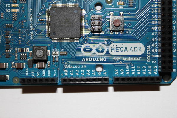
This is the first time you won't be using the digital IO pins of your ADK board. Instead, you will be using the analog input pins on your board. As their name already implies, they can only be used as inputs. The special thing about those pins is that they can measure analog values, meaning changes in the applied voltage. The ADK board is capable of translating those measured values into digital values. This procedure is called analog to digital conversion. This is done by an internal component called ADC, an analog to digital converter. In the case of the ADK board, it means that the values from 0V to 5V are mapped to digital values from 0 to 1023, so it is able to visualize the change in value in a 10-bit range. The analog input pins are placed on the opposite side of the digital pins on the board and are for the most part properly labeled with ANALOG IN and the pin number prefix A. So the analog pin 5 would be labeled A5. You can see those pins in Figure 4-9.
Potentiometer
A potentiometer is a variable resistor. It has three leads you can connect to a circuit. It has two functionalities, depending on how you connect it. If you just connect one of the outer terminals and the middle terminal to your circuit, it only serves as a simple variable resistor as shown in Figure 4-10.
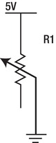
Figure 4-10. Potentiometer as variable resistor
If you also connect the third lead, it serves as a so-called voltage divider. A voltage divider (also called a potential divider) is a special circuit setup which, as the name implies, is capable of dividing the voltage in a circuit into different voltage levels among the circuit's components. A typical voltage divider circuit consists of two resistors in series or one potentiometer. A circuit visualization can be seen in Figure 4-11.
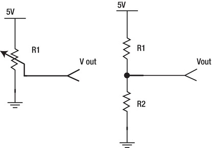
Figure 4-11. Voltage divider with potentiometer (left), voltage divider with two resistors in series (right)
Vin is the voltage which is applied across both resistors in series and Vout is the voltage across the second resistor (R2). The formula to determine the output voltage is as follows:
![]()
Let's see that in an example. Consider the use case in which you have a 9V battery but one of your electrical components only operates at a voltage level of 5V. You have already determined your Vin, which is 9V, and your Vout, which is 5V. The only thing missing is the resistor values, which you will need.
Let's try using a 27kΩ resistor for R2. The only thing missing now is R1. Put the values into the formula and it looks like this:
![]()
Rearrange the formula so that you can determine the missing variable R1.
Since you won't find such a specific resistor value you can take the next higher one, which is 22kΩ. With that value for R1 you will end up with 4.96V, which is very close to the targeted 5V.
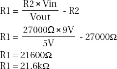
If you twist the potentiometer, you basically change its internal resistance proportion, meaning that if the resistance between the left terminal and the middle terminal decreases, the resistance between the right terminal and the middle terminal increases and vice versa. So if you apply that principle on the voltage divider formula, this would mean that if the value of R1 increases, it decreases at R2 and vice versa. So when the resistance proportion changes within the potentiometer, it causes a change in Vout. Potentiometers come in several shapes and resistance ranges. The most common types are the trimmer, which is adjusted by using a screwdriver or similar fitting object, and the rotary potentiometers, which have a shaft or knob to adjust the resistance value (shown in Figure 4-12). In this project I used the trimmer type because it is usually a bit cheaper than a rotary potentiometer.
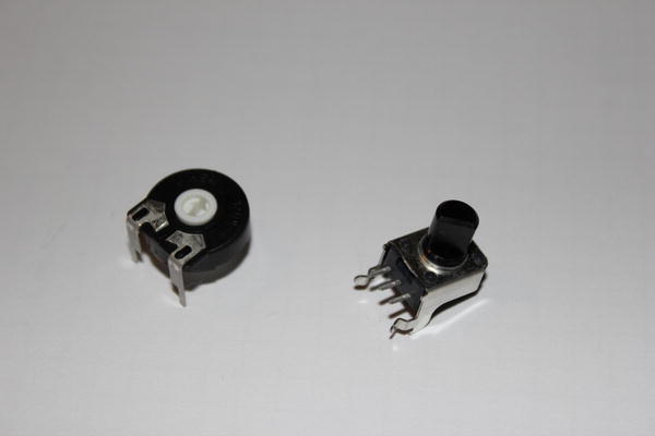
Figure 4-12. Potentiometer: trimmer (left), rotary potentiometer (right)
The Setup
The setup for this project is simple. Just connect the +5V pin to one of the outer leads of the potentiometer and a GND pin to the opposite outer lead. Connect analog pin A0 to the middle lead of the potentiometer and you're already done. Your setup should look like Figure 4-13. If you adjust your potentiometer, the measured value at the analog pin will change.

The Software
The Arduino sketch is responsible for reading the ADC value of the analog pin. The transmitted 10-bit value will be received by the Android application and the value change will be shown in a TextView and in a ProgressBar UI element. You will also learn a conversion technique to transmit large values.
The Arduino Sketch
Have a look at the complete Arduino sketch in Listing 4-3. I'll discuss what's new afterward.
Listing 4-3. Project 4: Arduino Sketch
#include <Max3421e.h>

#include <Usb.h>

#include <AndroidAccessory.h>


#define COMMAND_ANALOG 0x3

#define TARGET_PIN 0x0

#define INPUT_PIN A0


AndroidAccessory acc("Manufacturer",

                     "Model",

                     "Description",

                     "Version",

                     "URI",

                     "Serial");


byte sntmsg[6];

int analogPinReading;


void setup() {

  Serial.begin(19200);

  acc.powerOn();

  sntmsg[0] = COMMAND_ANALOG;

  sntmsg[1] = TARGET_PIN;

}


void loop() {

  if (acc.isConnected()) {

    analogPinReading = analogRead(INPUT_PIN);

    sntmsg[2] = (byte) (analogPinReading >> 24);

    sntmsg[3] = (byte) (analogPinReading >> 16);

    sntmsg[4] = (byte) (analogPinReading >> 8);

    sntmsg[5] = (byte) analogPinReading;

    acc.write(sntmsg, 6);

    delay(100);

  }

}
The first new method that can be seen is the analogRead method. It converts the analog voltage value to a 10-bit digital value. Since it is a 10-bit value it is too big to be stored in a byte variable. That's why you have to store it in an integer typed variable.
analogPinReading = analogRead(INPUT_PIN);
The problem is that you only can transmit bytes, so you have to transform and split the integer value into several bytes. The size of an integer as a data type is as big as 4 bytes, that's why you'll have to transform the integer to four single bytes which you can transmit later on. To transform the value, a technique called bit-shifting is used here. Bit-shifting means that the value is processed in its binary representation, which consists of single bits, and that you shift all the bits to a certain direction.
To better understand what bit-shifting is, have a look at an example. Imagine that you want to transmit the value 300. As you can already tell, this value is an integer. The binary representation of that value looks like this:
00000000 00000000 00000001 00101100 = 300
The mathematical correct expression for that is even shorter and would not require you to write all the leading zeros. It is just prefixed with 0b.
0b100101100 = 300
If you cast this value simply to a byte, only the last eight bits will form the byte value. In this case you would end up with a value of 44.
00101100 = 44
That's only one part of the whole value. To transform the rest of the bits, you need to get them into the proper places first. That's where bit-shifting is used. You can shift bits in both directions using either the operator <<, to shift them to the left side, or >>, to shift them to the right side. In this case you need a right shift, so you use the >> operator. You need to shift the value eight times to the right before you can cast it to a new byte. Since you need to shift it several times to construct all four bytes, the complete syntax would be this:
(byte) (300 >> 24)

(byte) (300 >> 16)

(byte) (300 >> 8)

(byte) 300
In its new binary representation, the above values look like this:
00000000

00000000

00000001

00101100
You can see that the shifted-out bits are simply dismissed. Now you can transmit all four data bytes and retransform them on the other side back to the initial integer.
The Android Application
In the Android application, the received four-byte value will be converted back to an integer value and the change in the measured value will be visualized by a TextView, which presents the current value. A second visual indicator will be the ProgressBar UI element. It looks similar to the already introduced SeekBar, but here the user has no possibility to interact with the bar. Have a look at the code in Listing 4-4. I'll explain the specifics afterward.
Listing 4-4. Project 4: ProjectFourActivity.java
package project.four.adk;


import …;


public class ProjectFourActivity extends Activity {


    …


    private static final byte COMMAND_ANALOG = 0x3;

    private static final byte TARGET_PIN = 0x0;


    private TextView adcValueTextView;

    private ProgressBar adcValueProgressBar;


    @Override

    public void onCreate(Bundle savedInstanceState) {

        super.onCreate(savedInstanceState);


        …


        setContentView(R.layout.main);

        adcValueTextView = (TextView) findViewById(R.id.adc_value_text_view);

        adcValueProgressBar = (ProgressBar) findViewById(R.id.adc_value_bar);

    }


    @Override

    public void onResume() {

        super.onResume();

        …

    }


    @Override

    public void onPause() {

        super.onPause();

        …

    }


    @Override

    public void onDestroy() {

        super.onDestroy();

        …

    }


    private final BroadcastReceiver mUsbReceiver = new BroadcastReceiver() {

        @Override

        public void onReceive(Context context, Intent intent) {

            …

        }

    };


    private void openAccessory(UsbAccessory accessory) {

        mFileDescriptor = mUsbManager.openAccessory(accessory);

        if (mFileDescriptor != null) {

            mAccessory = accessory;

            FileDescriptor fd = mFileDescriptor.getFileDescriptor();

            mInputStream = new FileInputStream(fd);

            mOutputStream = new FileOutputStream(fd);

            Thread thread = new Thread(null, commRunnable, TAG);

            thread.start();

            Log.d(TAG, "accessory opened");

        } else {

            Log.d(TAG, "accessory open fail");

        }

    }


    private void closeAccessory() {

        …

    }


    Runnable commRunnable = new Runnable() {


        @Override

        public void run() {

            int ret = 0;

            byte[] buffer = new byte[6];


            while (ret >= 0) {

                try {

                    ret = mInputStream.read(buffer);

                } catch (IOException e) {

                    Log.e(TAG, "IOException", e);

                    break;

                }


                switch (buffer[0]) {

                case COMMAND_ANALOG:


                    if (buffer[1] == TARGET_PIN) {

                        final int adcValue = ((buffer[2] & 0xFF) << 24)

     + ((buffer[3] & 0xFF) << 16)

     + ((buffer[4] & 0xFF) << 8)

     + (buffer[5] & 0xFF);

                        runOnUiThread(new Runnable() {


                            @Override

                            public void run() {

                                adcValueProgressBar.setProgress(adcValue);

                                adcValueTextView.setText(getString(R.string.adc_value_text,

                                    adcValue));

                            }

                        });

                    }

                    break;


                default:

                    Log.d(TAG, "unknown msg: " + buffer[0]);

                    break;

                }

            }

        }

    };

}
As you can see, the new variables in this code snippet are the same message definition bytes as in the Arduino sketch and the two UI elements I described at the beginning.
private static final byte COMMAND_ANALOG = 0x3;

private static final byte TARGET_PIN = 0x0;


private TextView adcValueTextView;

private ProgressBar adcValueProgressBar;
Have a look at the UI element definition that needs to be made in the main.xml layout file shown in Listing 4-5. In addition to the usual layout attributes of both elements, you have to define the max value attribute of the ProgressBar so that the graphical visualization can be made in the correct range from 0 to 1023.
You can see that there is a second attribute of importance. The style attribute tells the system to render the UI elements' appearance in a certain style. If the attribute is omitted, the ProgressBar will render in its default style, which is a loading-type spinning wheel. That's not what you want here so you can overwrite the style with another one. The syntax for that particular style lookup looks a little bit strange. The ?android: prefix means that this particular resource cannot be found in the current project's res folder but in the Android system resources.
Listing 4-5. Project 4: main.xml
<?xml version="1.0" encoding="utf-8"?>

<LinearLayout xmlns:android="http://schemas.android.com/apk/res/android"

    android:orientation="vertical"

    android:layout_width="fill_parent"

    android:layout_height="fill_parent"

    android:gravity="center">

    <TextView android:id="@+id/adc_value_text_view"

        android:layout_width="wrap_content"

        android:layout_height="wrap_content"/>

    <ProgressBar android:id="@+id/adc_value_bar"

        android:layout_width="fill_parent"

        android:layout_height="wrap_content"

        android:max="1023"

        style="?android:attr/progressBarStyleHorizontal"/>

</LinearLayout>
As in project 3 you are interested in the received input, so the logic of receiving data stays pretty much the same. A separate thread is responsible for reading the inputstream and processing the received message. You can see that the last four bytes of the received message are reconverted into an integer value again by using the bit-shifting technique—only this time, the shift happens in the other direction.
final int adcValue = ((buffer[2] & 0xFF) << 24)

     + ((buffer[3] & 0xFF) << 16)

     + ((buffer[4] & 0xFF) << 8)

     + (buffer[5] & 0xFF);
You also see that the byte values are altered before they are bit-shifted. This operation is called bitwise AND. By applying the value 0xFF you eliminate possible sign-bit errors when dealing with negative and positive numbers.
If you consider the example from before and imagine that the value that was measured is 300, then the four received bytes would have the following values without the bit-shifting:
00000000 = 0

00000000 = 0

00000001 = 1

00101100 = 44
To reconstruct the original integer value you need to left-shift the byte values as done above.
00000000 << 24 = 00000000 00000000 00000000 00000000 = 0

00000000 << 16 = 00000000 00000000 00000000 00000000 = 0

00000001 <<  8  = 00000000 00000000 00000001 00000000 = 256

00101100            = 00000000 00000000 00000000 00101100 = 44
Now if you add the received byte values you end up with the original integer value again.
0 + 0 + 256 + 44 = 300
The last thing to do is to visualize the value to the user. With the helper method runOnUiThread, both UI elements are updated. The TextView gets its text set accordingly and the ProgressBar sets its new progress value.
Upload both the Arduino sketch and the Android application and see how the value changes if you adjust the potentiometer. The final result is shown in Figure 4-14
Figure 4-14. Project 4: Final result
Summary
This chapter showed how you can read values from the input pins of your ADK board. You used the digital pins in their input configuration to read digital inputs of HIGH and LOW. A button or switch was used to toggle between those two states and an Android application expressed the current state by vibrating whenever the button was pressed or the switch got closed. You also learned about a second possibility to measure a range of values by converting analog voltage readings on the analog input pins of the ADK board to digital expressions in the range from 0 to 1023. An Android application visualized the current reading with a new UI element, the ProgressBar. You changed the appearance of a UI element by applying a different style. Along the way you learned about the principles of a voltage divider and a pull-up resistor and you learned that bit-shifting can serve as a way for data conversion.