
C H A P T E R 9
Making Things Move
Probably one of the most interesting aspects of hobby electronics is building robots or making your projects move. There are many ways of achieving general movement depending on the use case. One common way to make a project move is through motors. Motors are referred to as actuators because they act on something rather than sense something, as sensors do. Different kinds of motors provide different levels of freedom of movement and power. The three most common motors are DC motors, servos, and stepper motors (see Figure 9-1).
DC motors are electrical motors that run on direct current (DC) and are mostly used in toys such as remote-controlled cars and such. They provide a continuous rotation of an axis that can be connected to gears to achieve different power transmissions. They have no positional feedback, meaning you can’t determine how many degrees the motor has turned.
Servos are commonly used in robots to move joints of an arm or a leg, for example. Their rotation is mostly restricted to a certain range of degrees. Most servos provide no continuous rotation and only support movement in the range of 180 degrees. However, there are special servos capable of rotating a full 360 degrees and there are even hacks of restricted servos to suppress their 180-degree restriction. Servos have positional feedback, which makes it possible to set them to a certain position by sending a specific signal.
Stepper motors are mainly used for precise machine movement as in scanners or printers. They provide full rotation with precise positional feedback. That allows gears or conveyer belts to move to exact positions when they are attached to a stepper motor.
Since stepper motor projects aren’t as popular as DC motor projects and servo projects, I will only describe the latter in this chapter. However, if you want to give stepper motors a try, you can find some tutorials on the Arduino website at http://arduino.cc/hu/Tutorial/StepperUnipolar and http://arduino.cc/en/Tutorial/MotorKnob.

Figure 9-1. Motors (DC motor, servo, stepper motor)
Project 10: Controlling Servos
Servos are perfect for controlling limited movement. In order to control a servo you will need to send different waveforms to the servo via a digital pin of your ADK board. To define in which direction your servo should move, you will write an Android application that utilizes your device’s accelerometer sensor. So when you tilt your device in a certain direction along the x-axis, your servo will reflect the relative movement as well.
What the device’s accelerometer actually does is to measure the acceleration applied to the device. The acceleration is the rate of change of velocity relative to a set of axes. The force of gravity influences the measured acceleration. When the Android device is resting on a table, no acceleration will be measured. When tilting the device along one of its axes, the acceleration along that axis changes. (See Figure 9-2).
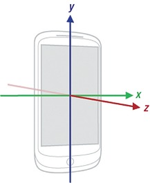
Figure 9-2. Device axes overview (image property of Google Inc., under Creative Commons 2.5, http://developer.android.com/reference/android/hardware/SensorEvent.html)
The Parts
Luckily servos don’t need fancy circuits or additional parts. They just have one data line that receives waveform pulses to set the servo in the correct position. So in addition to a servo you’ll only need your ADK board and some wires (shown in Figure 9-3).
- ADK board
- Servo
- Some wires
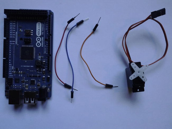
Figure 9-3. Project 10 parts (ADK board, wires, servo)
ADK Board
As in previous projects in which you had to generate waveforms, you will use one of the digital pins of your ADK board. The ADK board will send electrical pulses to the servo. The widths of these pulses are responsible for setting the servo to a specific position. To produce the necessary waveforms you can either implement the logic on your own by setting a digital pin to an alternating HIGH/LOW signal in a defined period of time or you can use the Arduino Servo library, but more on that later.
Servo
As already described, a servo is a kind of motor limited for the most part to turning its axis within a predefined range. The range for hobby servos is usually 180 degrees. The restriction is achieved mechanically by blocking an internal gear when it reaches the predefined position. You can find hacks on the Web to get rid of that block but you have to open up your servo to break the blocking and do some soldering afterwards. Another possibility to get more rotational freedom is to use a special 360-degree servo. Those tend to be a bit more expensive, which is why the hacking of low-budget 180-degree servos seems to be a good alternative for some people. Anyway, in most cases you won’t need a full rotational servo for most projects. You would be better off using a DC motor or a stepper motor in those use cases.
So how does a servo work? Basically, a servo is just an electric motor that transfers its power to a set of gears that can turn an axis in a predefined range of degrees. The range for turning the axis is mechanically limited. An integrated circuit, combined with a potentiometer, receives waveform pulses sent to the servo and determines to which angle the servo has to be set. The usual hobby servos operate with pulses in the frequency of 50Hz, which describes a signal-period of about 20ms. The amount of time in which the signal is set to HIGH specifies the servo angle. According to the servo industry standard, the signal has to be set to HIGH for 1ms and afterward set to LOW for the remaining time to move the servo to its outmost left position. To move the servo to its outmost right position the signal has to be set to HIGH for 2ms and afterward set to LOW for the remaining time. (See Figure 9-4.) Note that those signal times are defaults and they may differ in practice from servo to servo, so the values could be even lower for the left position or higher for the right position. In some cases you won’t even have to adhere to the 20ms period, so even that could be defined as even shorter. In general, you should stick to the defaults first and only change those values if you run into trouble.

Figure 9-4. Servo control signal waveforms (top : full left position, bottom: full right position)
Servos come in many different form factors for different use cases (Figure 9-5). In hobby electronics, you’ll find small servos for model planes or robots. Those servos can differentiate in size and speed but they are generally small and are easily mountable.

Figure 9-5. Different servo form factors
Most servos come with different attachments for their drive shaft or axis, so that you can use them as joints for robots or to control a rudder on a model plane or ship. (See Figure 9-6).
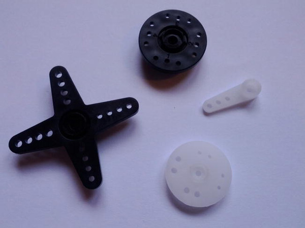
Figure 9-6. Servo drive shaft attachments
Since you don’t need a special circuit to control a servo, connecting a servo is very straightforward if you have a microcontroller capable of producing the required waveforms. A servo has three wires attached to it. Usually they are colored in a certain way. You have a red wire, which is Vin, and it connects to +5V. However, you should read the datasheet to see if your servo has a different input voltage rating. The black wire has to be connected to ground (GND). The last wire, which is usually orange, yellow, or white, is the data line. That’s where you connect the digital output pin of your microcontroller. It is used to transmit the pulses to the servo, which in turn moves to the desired position.
The Setup
Since you won’t have to build a special circuit for this project, you can connect your servo directly to your ADK board. As described before, connect the red wire to +5V, the black wire to GND, and the orange, yellow, or white wire to digital pin 2. Servos usually come with female connectors, so you either connect wires directly to the connector or use a male-to-male connector in between. (See Figure 9-7).

The Software
To control the servo you will write an Android application that requests updates of its accelerometer sensor’s current tilt on the x-axis. When you tilt your device left or right, you will send the resulting orientation update to the ADK board. The Arduino sketch receives the new tilt value and sends the corresponding positioning pulse to the servo.
The Arduino Sketch
The Arduino sketch is responsible for receiving the accelerometer data and setting the servo to the correct position. You have two possibilities for doing that. You can either implement your own method for creating the desired waveform to send to the servo, or you can use the Servo library that comes with the Arduino IDE. Personally, I prefer to use the library because it is more precise, but I will show you both approaches here. You can decide which solution fits better to your needs.
Manual Waveform Generation
The first approach is to implement the waveform generation on your own. Have a look at the complete Listing 9-1 first.
Listing 9-1. Project 10: Arduino Sketch (Custom Waveform Implementation)
#include <Max3421e.h>

#include <Usb.h>

#include <AndroidAccessory.h>


#define COMMAND_SERVO 0x7

#define SERVO_ID_1 0x1
#define SERVO_ID_1_PIN 2


int highSignalTime;

float microSecondsPerDegree;

// default boundaries, change them for your specific servo

int leftBoundaryInMicroSeconds = 1000;

int rightBoundaryInMicroSeconds = 2000;


AndroidAccessory acc("Manufacturer", "Model", "Description",

                     "Version", "URI", "Serial");


byte rcvmsg[6];


void setup() {

  Serial.begin(19200);

  pinMode(SERVO_ID_1_PIN, OUTPUT);

  acc.powerOn();

  microSecondsPerDegree = (rightBoundaryInMicroSeconds – leftBoundaryInMicrosSeconds) / 180.0;

}


void loop() {

  if (acc.isConnected()) {

    int len = acc.read(rcvmsg, sizeof(rcvmsg), 1);

    if (len > 0) {

      if (rcvmsg[0] == COMMAND_SERVO) {

        if(rcvmsg[1] == SERVO_ID_1) {

          int posInDegrees = ((rcvmsg[2] & 0xFF) << 24)

                  + ((rcvmsg[3] & 0xFF) << 16)

                  + ((rcvmsg[4] & 0xFF) << 8)

                  + (rcvmsg[5] & 0xFF);

          posInDegrees = map(posInDegrees, -100, 100, 0, 180);

          moveServo(SERVO_ID_1_PIN, posInDegrees);

        }

      }

    }

  }

}


void moveServo(int servoPulsePin, int pos){

  // calculate time for high signal

  highSignalTime = leftBoundaryInMicroSeconds + (pos * microSecondsPerDegree);

  // set Servo to HIGH

  digitalWrite(servoPulsePin, HIGH);

  // wait for calculated amount of microseconds

  delayMicroseconds(highSignalTime);

  // set Servo to LOW

  digitalWrite(servoPulsePin, LOW);

  // delay to complete waveform

  delayMicroseconds(20000 – highSignalTime);

}
As always, let’s begin by having a look at the variables of the sketch.
#define COMMAND_SERVO 0x7

#define SERVO_ID_1 0x1

#define SERVO_ID_1_PIN 2
You can see that a new command-type constant is defined for the servo control messages. The second constant is the ID of the servo, which should be controlled, in case that you want to attach more than one to your ADK board. The third constant is the corresponding pin on the ADK board where your servo is connected. Next, you have some variables to specify the waveform later on.
int highSignalTime;

float microSecondsPerDegree;

int leftBoundaryInMicroSeconds = 1000;

int rightBoundaryInMicroSeconds = 2000;
The variable highSignalTime is calculated later on and it describes the amount of time in microseconds for which the signal is set to HIGH. As you remember, setting the signal to HIGH for about 1ms means turning the servo left, and setting it to HIGH for about 2ms results in the servo turning right. The microSecondsPerDegree variable is used for conversion purposes and it describes, as the name already implies, the necessary microseconds that have to be added to the HIGH signal time per degree. The last two variables are the servo boundaries in microseconds. As already stated, a HIGH signal of about 1ms should result in full servo movement to the left, and 2ms should result in full movement to the right. In practice, however, that’s usually not the case. If you work with those default values you might see that your servo won’t turn to its full potential. You should experiment with the boundary values to adjust the code to your servo as each servo is different. I even had to change the defaults for one of my servos to the boundaries from 600 to 2100, which means that the servo fully moved to the left if I applied a HIGH signal for 0.6ms and it moved fully to the right if I applied a HIGH signal for about 2.1ms. As you can see, you can work with the defaults but, if you experiencing problems, you should experiment with the servo’s boundaries.
In the setup method you will have to set the pinMode for the servo’s signal pin as an output.
pinMode(SERVO_ID_1_PIN, OUTPUT);
You should also calculate here the microseconds per degree so that you can use the value later on in your positioning calculations.
microSecondsPerDegree = (rightBoundaryInMicroSeconds - leftBoundaryInMicroSeconds) / 180.0;
The calculation is easy. Since your servo most likely only has a range of up to 180 degrees, you just need to divide the difference between the right boundary value and the left boundary value by 180.
Next up is the loop method. After reading the received data message from the Android application, you need to decode the transmitted value by using the bit-shifting technique.
int posInDegrees = ((rcvmsg[2] & 0xFF) << 24)

                  + ((rcvmsg[3] & 0xFF) << 16)

                  + ((rcvmsg[4] & 0xFF) << 8)

                  + (rcvmsg[5] & 0xFF);
The Android application you will write afterward will transmit values from -100 for the left position and 100 for the right position. Since you need to provide the corresponding degrees for the servo position, you’ll need to use the map function first.
posInDegrees = map(posInDegrees, -100, 100, 0, 180);
The position value can now be given to your custom moveServo method along with the signal pin of the corresponding servo.
moveServo(SERVO_ID_1_PIN, posInDegrees);
The implementation of the moveServo method describes the construction of the necessary waveform to control the servo.
void moveServo(int servoPulsePin, int pos){

  // calculate time for high signal

  highSignalTime = leftBoundaryInMicroSeconds + (pos * microSecondsPerDegree);

  // set Servo to HIGH

  digitalWrite(servoPulsePin, HIGH);

  // wait for calculated amount of microseconds

  delayMicroseconds(highSignalTime);

  // set Servo to LOW

  digitalWrite(servoPulsePin, LOW);

  // delay to complete waveform

  delayMicroseconds(20000 - highSignalTime);

}
Let’s work through this with an example. Consider that you received a desired position of 90 degrees. To determine the time of the HIGH signal you would multiply 90 with microSecondsPerDegree and add the left boundary value. If you are using the default boundary values, then your calculation looks like this:
highSignalTime = 1000 + (90 * 5.55556);
This results in a HIGH signal time of about 1500 microseconds, so it should be the middle position of the servo. What you have to do now is set the signal pin of your servo to digital HIGH wait for the calculated amount of time and afterward set it to LOW again. The remaining delay for one signal-period of 20ms can now be calculated to complete a full pulse. That’s all there is to it.
Waveform Generation with Servo Library
As you can see, implementing the waveform generation is not particularly hard, but it can be made even easier if you use the Servo library that comes with the Arduino IDE. Listing 9-2 shows the sketch rewritten using the Servo library.
Listing 9-2. Project 10: Arduino Sketch (Using the Servo Library)
#include <Max3421e.h>

#include <Usb.h>

#include <AndroidAccessory.h>

#include <Servo.h>


#define COMMAND_SERVO 0x7

#define SERVO_ID_1 0x1

#define SERVO_ID_1_PIN 2


Servo servo;


AndroidAccessory acc("Manufacturer", "Model", "Description",
                     "Version", "URI", "Serial");


byte rcvmsg[6];


void setup() {

  Serial.begin(19200);

  servo.attach(SERVO_ID_1_PIN);

  acc.powerOn();

}


void loop() {

  if (acc.isConnected()) {

    int len = acc.read(rcvmsg, sizeof(rcvmsg), 1);

    if (len > 0) {

      if (rcvmsg[0] == COMMAND_SERVO) {

        if(rcvmsg[1] == SERVO_ID_1) {

          int posInDegrees = ((rcvmsg[2] & 0xFF) << 24)

                  + ((rcvmsg[3] & 0xFF) << 16)

                  + ((rcvmsg[4] & 0xFF) << 8)

                  + (rcvmsg[5] & 0xFF);

          posInDegrees = map(posInDegrees, -100, 100, 0, 180);

          servo.write(posInDegrees);

          // give the servo time to reach its position

          delay(20);

        }

      }

    }

  }

}
At first glance, you can see that the code got a lot shorter. You won’t need any calculations or custom methods anymore. To use the Servo library, you first have to include it in your sketch.
#include <Servo.h>
By including it in your sketch, you can work with a Servo object that does all the heavy lifting for you.
Servo servo;
To initialize the Servo object you have to call the attach method and provide the digital pin to which the servo’s signal wire is connected.
servo.attach(SERVO_ID_1_PIN);
To actually control the servo you just have to call its write method along with your desired position value in degrees.
servo.write(posInDegrees);

delay(20);
Note that you have to call the delay method here to give the servo some time to reach its position and to complete a full pulse. If you did not provide a delay the servo would just jitter, as the positional updates would come in too fast. The waveform generation is handled within the Servo library in the background so you don’t have to worry about that anymore. It’s a lot easier, isn’t it?
That’s it for the Arduino part. Remember, you can choose which approach best fits your needs as you implement your Arduino sketch.
The Android Application
Most Android devices have means to identify their orientation in three-dimensional space. Usually they achieve this by requesting sensor updates from their accelerometer sensors and their magnetic field sensors. For the Android part you will also request orientation updates from the accelerometer, which will directly relate to the servo’s movement later on. Listing 9-3 shows the activity implementation, which I’ll discuss in detail after.
Listing 9-3. Project 10: ProjectTenActivity.java
package project.ten.adk;


import …;


public class ProjectTenActivity extends Activity {


    …


    private static final byte COMMAND_SERVO = 0x7;

    private static final byte SERVO_ID_1 = 0x1;


    private TextView servoDirectionTextView;


    private SensorManager sensorManager;

    private Sensor accelerometer;


    /** Called when the activity is first created. */

    @Override

    public void onCreate(Bundle savedInstanceState) {

        super.onCreate(savedInstanceState);


        …


        setContentView(R.layout.main);

        servoDirectionTextView = (TextView) findViewById(R.id.x_axis_tilt_text_view);


        sensorManager = (SensorManager) getSystemService(SENSOR_SERVICE);

        accelerometer = sensorManager.getDefaultSensor(Sensor.TYPE_ACCELEROMETER);

    }


    /**

     * Called when the activity is resumed from its paused state and immediately

     * after onCreate().

     */

    @Override

    public void onResume() {

        super.onResume();
        sensorManager.registerListener(sensorEventListener, accelerometer,

            SensorManager.SENSOR_DELAY_GAME);


        …


    }


    /** Called when the activity is paused by the system. */

    @Override

    public void onPause() {

        super.onPause();

        closeAccessory();

        sensorManager.unregisterListener(sensorEventListener);

    }


    /**

     * Called when the activity is no longer needed prior to being removed from

     * the activity stack.

     */

    @Override

    public void onDestroy() {

        super.onDestroy();

        unregisterReceiver(mUsbReceiver);

    }


    private final SensorEventListener sensorEventListener = new SensorEventListener() {


        int x_acceleration;


        @Override

        public void onAccuracyChanged(Sensor sensor, int accuracy) {

            // not implemented

        }


        @Override

        public void onSensorChanged(SensorEvent event) {

            x_acceleration = (int)(-event.values[0] * 10);

            moveServoCommand(SERVO_ID_1, x_acceleration);

            runOnUiThread(new Runnable() {


                @Override

                public void run() {

                    servoDirectionTextView.setText(getString(
                        R.string.x_axis_tilt_text_placeholder, x_acceleration));

                }

            });

        }

    };


    private final BroadcastReceiver mUsbReceiver = new BroadcastReceiver() {
        @Override

        public void onReceive(Context context, Intent intent) {

            …

        }

    };


    private void openAccessory(UsbAccessory accessory) {

        …

    }


    private void closeAccessory() {

        …

    }


    public void moveServoCommand(byte target, int value) {

        byte[] buffer = new byte[6];

        buffer[0] = COMMAND_SERVO;

        buffer[1] = target;

        buffer[2] = (byte) (value >> 24);

        buffer[3] = (byte) (value >> 16);

        buffer[4] = (byte) (value >> 8);

        buffer[5] = (byte) value;

        if (mOutputStream != null) {

            try {

                mOutputStream.write(buffer);

            } catch (IOException e) {

                Log.e(TAG, "write failed", e);

            }

        }

    }

}
As was done in the Arduino sketch, you’ll first have to define the same command and target IDs for your control message you intend to send later on.
private static final byte COMMAND_SERVO = 0x7;

private static final byte SERVO_ID_1 = 0x1;
The only visual component you will use is a simple TextView element for debugging purposes and to give you an overview on how the orientation value of the x-axis changes when you tilt your device.
private TextView servoDirectionTextView;
In order to request updates from any sensor of your Android device you will first need to acquire references to the SensorManager and the Sensor itself. There are other ways to fetch data from certain sensors, but the SensorManager is a general registry for most of them.
private SensorManager sensorManager;

private Sensor accelerometer;
After doing the usual setup of your content view elements in the onCreate() method, you acquire the aforementioned reference to the SensorManager by calling the context method getSystemService and providing the SENSOR_SERVICE constant as a parameter. This method provides access to all kinds of system services such as connectivity services, audio services, and so on.
With the SensorManager ready to be used you have access to the Android device’s sensors. You want the accelerometer sensor in particular, so that’s what you have to specify as a parameter when you call the getDefaultSensor method on the SensorManager.
accelerometer = sensorManager.getDefaultSensor(Sensor.TYPE_ACCELEROMETER);
The Android system provides a mechanism to register for sensor changes so that you don’t have to worry about that. Since you can’t get sensor readings directly from the Sensor object you will have to register for those SensorEvents.
In the onResume() method you call the registerListener method on the SensorManager object and pass along three parameters. The first is a SensorEventListener, which implements methods to react on sensor changes. (I will come to that in a moment.) The second parameter is the actual Sensor reference, which should be listened to. The last parameter is the update rate.
There are different rate constants defined in the SensorManager class. I had the best experience with the SENSOR_DELAY_GAME constant. It gives a very fast update rate. The normal delay caused somewhat laggy behavior in the servo movement. I would not recommend using the SENSOR_DELAY_FASTEST constant, either, as this usually makes the servo jitter a lot; the updates come in too quickly.
sensorManager.registerListener(sensorEventListener, accelerometer,

    SensorManager.SENSOR_DELAY_GAME);
Since you registered the listener in the onResume() method you should also make sure that the application frees up resources and cancels the listening process in the onPause() method accordingly.
sensorManager.unregisterListener(sensorEventListener);
Now let’s have a look at the listener itself since it is responsible for handling the sensor updates.
private final SensorEventListener sensorEventListener = new SensorEventListener() {


    int x_acceleration;


    @Override

    public void onAccuracyChanged(Sensor sensor, int accuracy) {

        // not implemented

    }


    @Override

    public void onSensorChanged(SensorEvent event) {

        x_acceleration = (int)(-event.values[0] * 10);

        moveServoCommand(SERVO_ID_1, x_acceleration);

        runOnUiThread(new Runnable() {


            @Override

            public void run() {

                servoDirectionTextView.setText(getString(
                    R.string.x_axis_tilt_text_placeholder, x_acceleration));

            }

        });

    }

};
When you implement a SensorEventListener you will have to write two methods, the onAccuracyChanged method and the onSensorChanged method. The first is not really of interest to you in this project; you don’t care about accuracy right now. The second, however, provides a parameter called SensorEvent that is provided by the system and holds the sensor values you are interested in. The SensorEvent values for the accelerometer contain three values, the acceleration on the x-axis, the acceleration on the y-axis and the acceleration on the z-axis. You are only interested in the acceleration on the x-axis so you only need to worry about the first value. The values returned are in the range from 10.0, for complete left tilt, to -10.0, for complete right tilt. This seems a bit counter-intuitive for the user seeing those values later on. That’s why the values have been negated in this example project. For easier transmission of the values it is also best to multiply the values by the factor of ten so that you can transmit integer numbers rather than floats later on. By doing so, the transmittable numbers will be in the range from -100 to 100.
x_acceleration = (int)(-event.values[0] * 10);
Now that you have the acceleration data on the x-axis, you can update the TextView element to give visual feedback.
runOnUiThread(new Runnable() {


    @Override

    public void run() {

        servoDirectionTextView.setText(getString(
            R.string.x_axis_tilt_text_placeholder, x_acceleration));

    }

});
The last thing to do is to send the control message to the ADK board. For that purpose you’ll use the custom method moveServoCommand by providing the ID of the servo to be controlled and the actual acceleration data.
moveServoCommand(SERVO_ID_1, x_acceleration);
The method’s implementation is straightforward. You’ll just set up the basic data structure, bit-shift the integer acceleration value to four single bytes, and send the complete message via the outputstream to the ADK board.
public void moveServoCommand(byte target, int value) {

    byte[] buffer = new byte[6];

    buffer[0] = COMMAND_SERVO;

    buffer[1] = target;

    buffer[2] = (byte) (value >> 24);

    buffer[3] = (byte) (value >> 16);

    buffer[4] = (byte) (value >> 8);

    buffer[5] = (byte) value;

    if (mOutputStream != null) {

        try {

            mOutputStream.write(buffer);

        } catch (IOException e) {

            Log.e(TAG, "write failed", e);

        }

    }

}
That’s it for the Android part, the final result of which is shown in Figure 9-8. When you’re ready, deploy both applications and see how your servo turns whenever you tilt your Android device sideways.
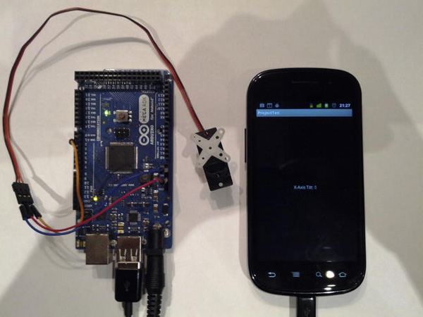
Figure 9-8. Project 10: Final result
Project 11: Controlling DC Motors
The next project shows you how to control another kind of motor, a so-called DC motor. As I already explained at the beginning of this chapter, DC motors provide continuous rotation and are not artificially limited the way servos are. You will again use your device’s accelerometer to control the DC motor, only this time you will work with the acceleration changes along the y-axis of your device. So when you tilt your device forward, the motor will begin to spin. You will also be able to control its speed while doing that. Note that I don’t cover spin direction changes, which require a bit more hardware. Before you begin, you’ll need to learn about the parts you will need to control a DC motor and how the motor operates.
The Parts
You won’t need many parts to get the motor running. In fact, the only new component for the circuit you are about to build is a so-called NPN transistor. I will explain its purpose in a moment.
![]() Note If you are using an Arduino design–based ADK board and you happen to use a DC motor that operates at a voltage higher than 5V, or if it consumes more than 40mA, you might need an additional external power supply as the output pins of the board are limited to those values.
Note If you are using an Arduino design–based ADK board and you happen to use a DC motor that operates at a voltage higher than 5V, or if it consumes more than 40mA, you might need an additional external power supply as the output pins of the board are limited to those values.
The part list looks like this (Figure 9-9):
- ADK board
- Breadboard
- NPN transistor (BC547B)
- DC motor
- Some wires
- Optional: 1-10kΩ resistor, external battery
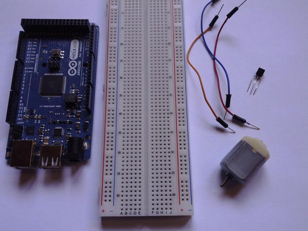
Figure 9-9. Project 11 parts (ADK board, breadboard, wires, NPN transistor, DC motor)
ADK Board
You will be using the pulse-width modulation (PWM) capability of an output pin to produce the different voltages that influence the motor’s speed later on.
DC Motor
DC motors run on direct current, hence their name. There are two types of DC motors: brushed DC motors and brushless DC motors.
Brushed DC motors work on the principle that stationary magnets interfere with an electromagnetic field. A mounted coil on the driveshaft generates an electromagnetic field around its armature, which constantly gets attracted and rejected by the surrounding stationary magnets, causing the drive shaft to spin. Brushed DC motors are usually cheaper than brushless DC motors, which is why they are more widely used in hobby electronics.
Brushless DC motors are built just like the opposite of brushed DC motors. They have stationary magnets mounted on their drive shaft that are set in motion when an electromagnetic field is applied to them. What’s also different about them is that a motor controller converts the direct current (DC) to alternating current (AC). Brushless DC motors are a bit more expensive than their counterparts. Different DC motor form factors are shown in Figure 9-10.
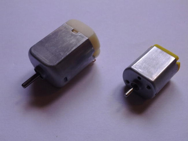
Figure 9-10. DC motors in different form factors
Most of the hobby DC motors have a two-wire connection, Vin and GND. To change the direction of the spin, you usually just change the polarity of the connections. When you want to switch the spin direction of the motor on the fly, you need a more sophisticated circuit than the one you are about to build here. For those purposes you would need a special circuit setup called H-bridge or a special motor driver IC. For further details about those just search the Web, where you will find plenty of tutorials and information. To avoid complicating the project, I will stick to only one motor direction. The speed of the motor can be influenced by the voltage level applied. The more you supply the faster it generally gets, but be careful not to supply more than it can handle. A quick look at the datasheet of the motor will give you an overview of the operating voltage range.
DC motors are usually used in conjunction with gears and transmissions, so that their torque can be projected onto those gears to turn, for example, wheels or other mechanical constructions. (See Figure 9-11.)
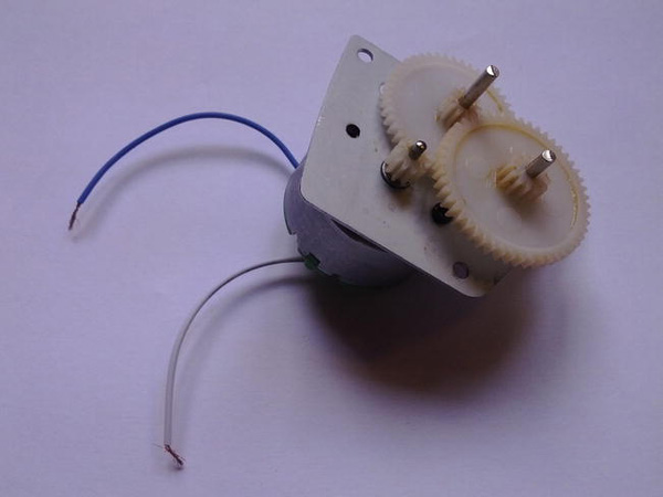
Figure 9-11. DC motor with gear attachment
Note that most DC motors don’t come with preattached wires, so you might have to solder on wires first.
NPN Transistor (BC547B)
Transistors are semiconductors capable of switching and amplifying power in a circuit. They usually have three connectors called base, collector, and emitter (see Figure 9-12).

Figure 9-12. Transistor (flat side facing toward: emitter, base, collector)
A transistor is able to influence the current flow between one pair of the connections by applying a smaller voltage or current to the other pair. So, for example, when current is flowing from the collector to the emitter, you can apply a smaller fraction of that current to the base flowing through the emitter to control the higher current. So basically a transistor can be used as a switch or amplifier for the power in a circuit.
There are several different types of transistors for different tasks. In this project you will need an NPN transistor. An NPN transistor operates with the base connector pulled high, meaning that it is set “on” when a high voltage or current is applied to the base. So when the voltage on the base increases, the connection from collector to emitter will let more current pass through. The electrical symbol for an NPN transistor is shown in Figure 9-13.

Figure 9-13. Electrical symbol for NPN transistor
The opposite of the NPN transistor is the PNP transistor, which operates in the exact opposite way. To switch the current flow between the collector and emitter, you need to pull the base low. So with a decreasing voltage you let more current pass through the collector-emitter connection. The electrical symbol for PNP transistors is shown in Figure 9-14.

Figure 9-14. Electrical symbol for PNP transistor
You will be using a NPN transistor to control the power applied to the motor later on so that you can control its speed.
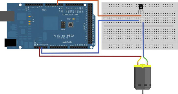
The Setup
The connection setup for this chapter’s second project is fairly easy as well (Figure 9-15). Depending on the DC motor you use, you connect one wire of the motor determined by your motor’s voltage rating to either +3.3V or 5V. If you happen to use a motor that works with even higher voltage ratings, you might want to connect an external battery. In that case you’ll have to make sure to connect the battery and the ADK board to a common ground (GND). The second wire of the motor needs to be connected to the collector of the transistor. The emitter of the transistor is connected to GND and the base of the transistor is connected to the digital pin 2. If you are having trouble finding the correct connection on the transistor just hold the transistor facing the flat side toward you. The right pin is the collector, the middle pin is the base, and the left pin is the emitter.
The NPN transistor has been added to the circuit in case your motor needs more power than the ADK board can supply. So if you are experiencing a really slow running motor or no movement at all you can easily attach an external battery to the circuit. If you do that you should make sure to also add a high valued resistor in the range from 1kΩ to 10kΩ to the digital pin 2 to keep the ADK board safe from power anomalies that might come from the higher-powered circuit. If you need an external battery your circuit would look like Figure 9-16.
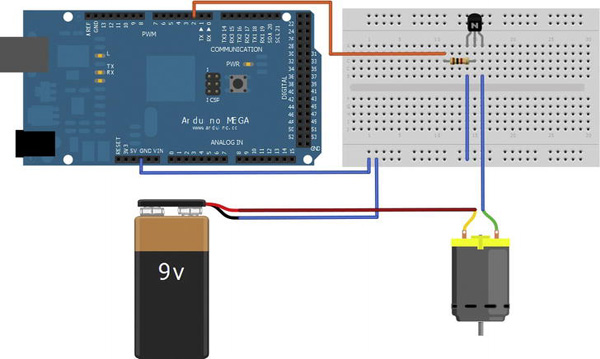
Figure 9-16. Project 11 setup with external battery
You should try using the first circuit setup first, but if your motor needs more power it is easy to just switch to the second circuit setup.
The Software
The software component of this little project is fairly easy. You will use the Android device’s accelerometer again to acquire the change of the tilt value when the device is tilted, only this time you are interested in the tilt value of the y-axis instead of the x-axis. The y-axis tilt describes the tilt motion when your device’s screen is facing upward and its top edge gets pushed down and its bottom edge gets pulled up. It’s as though you were to push a throttle lever in an airplane forward. The tilt value will be transmitted to the ADK board and the running Arduino sketch will map the received value, which will be only in the range from 0 to 100, since you are not interested in the other tilt direction, to a value between 0 and 255 to feed into the analogWrite method. This causes the digital pin 2 to act in its PWM mode and the output voltage of the pin will change accordingly. Remember that the transistor’s base connector is connected to pin 2, so with the changing voltage you will influence the overall power provided for the motor and the speed will vary according to your tilt.
The Arduino Sketch
The Arduino sketch will be a bit shorter than the one you wrote for controlling the servo (shown in Listing 9-4). There are no official DC motor libraries that come with the Arduino IDE, but for this example you won’t need a library because the code is really simple. There are custom libraries on the Web written by the community, for the case in which you use an H-bridge to also control the spin direction, but this is out of scope for the example here. You will only need to use the analogWrite method to change the voltage output on the digital pin 2 according to the tilt value you will receive from the connected Android device.
Listing 9-4. Project 11: Arduino Sketch
#include <Max3421e.h>

#include <Usb.h>

#include <AndroidAccessory.h>


#define COMMAND_DC_MOTOR 0x8

#define DC_MOTOR_ID_1 0x1

#define DC_MOTOR_ID_1_PIN 2


AndroidAccessory acc("Manufacturer", "Model", "Description",

                     "Version", "URI", "Serial");


byte rcvmsg[3];


void setup() {

  Serial.begin(19200);

  pinMode(DC_MOTOR_ID_1_PIN, OUTPUT);

  acc.powerOn();

}


void loop() {

  if (acc.isConnected()) {

    int len = acc.read(rcvmsg, sizeof(rcvmsg), 1);

    if (len > 0) {

      if (rcvmsg[0] == COMMAND_DC_MOTOR) {

        if(rcvmsg[1] == DC_MOTOR_ID_1) {

          int motorSpeed = rcvmsg[2] & 0xFF;

          motorSpeed = map(motorSpeed, 0, 100, 0, 255);

          analogWrite(DC_MOTOR_ID_1_PIN, motorSpeed);

        }

      }

    }

  }

}
The first thing to do here is to change the command and target bytes as usual.
#define COMMAND_DC_MOTOR 0x8

#define DC_MOTOR_ID_1 0x1

#define DC_MOTOR_ID_1_PIN 2
Next you configure the digital pin 2 as an output pin.
pinMode(DC_MOTOR_ID_1_PIN, OUTPUT);
Once you have received a valid message from the connected Android device you’ll have to convert the original tilt value from a byte to an int.
Since the analogWrite method works with values from 0 to 255 rather than with values from 0 to 100, you’ll have to map them to the appropriate range first before feeding them to the analogWrite method.
motorSpeed = map(motorSpeed, 0, 100, 0, 255);
Finally you can do the call to the analogWrite method by providing the target pin 2 and the converted value for the motor’s speed.
analogWrite(DC_MOTOR_ID_1_PIN, motorSpeed);
This short snippet of code is all there is to do to control a simple DC motor’s speed in one direction.
The Android Application
The Android application is almost the same as in the previous servo project. The only things that need changing are the message bytes and the value you get when a SensorEvent is received by the SensorEventListener. Let’s have a look what needs to be done (Listing 9-5).
Listing 9-5. Project 11: ProjectElevenActivity.java
package project.eleven.adk;


import …;


public class ProjectElevenActivity extends Activity {


    …


    private static final byte COMMAND_DC_MOTOR = 0x8;

    private static final byte DC_MOTOR_ID_1 = 0x1;


    private TextView motorSpeedTextView;


    private SensorManager sensorManager;

    private Sensor accelerometer;


    /** Called when the activity is first created. */

    @Override

    public void onCreate(Bundle savedInstanceState) {

        super.onCreate(savedInstanceState);


        …


        setContentView(R.layout.main);

        motorSpeedTextView = (TextView) findViewById(R.id.y_axis_tilt_text_view);


        sensorManager = (SensorManager) getSystemService(SENSOR_SERVICE);

        accelerometer = sensorManager.getDefaultSensor(Sensor.TYPE_ACCELEROMETER);

    }
    /**

     * Called when the activity is resumed from its paused state and immediately

     * after onCreate().

     */

    @Override

    public void onResume() {

        super.onResume();


        sensorManager.registerListener(sensorEventListener, accelerometer,
            SensorManager.SENSOR_DELAY_GAME);


        …


    }


    /** Called when the activity is paused by the system. */

    @Override

    public void onPause() {

        super.onPause();

        closeAccessory();

        sensorManager.unregisterListener(sensorEventListener);

    }


    /**

     * Called when the activity is no longer needed prior to being removed from

     * the activity stack.

     */

    @Override

    public void onDestroy() {

        super.onDestroy();

        unregisterReceiver(mUsbReceiver);

    }


    private final SensorEventListener sensorEventListener = new SensorEventListener() {


        int y_acceleration;


        @Override

        public void onAccuracyChanged(Sensor sensor, int accuracy) {

            // not implemented

        }


        @Override

        public void onSensorChanged(SensorEvent event) {

            y_acceleration = (int)(-event.values[1] * 10);

            if(y_acceleration < 0) {

                y_acceleration = 0;

            } else if(y_acceleration > 100) {

                y_acceleration = 100;

            }

            moveMotorCommand(DC_MOTOR_ID_1, y_acceleration);

            runOnUiThread(new Runnable() {
                @Override

                public void run() {

                    motorSpeedTextView.setText(getString(
                        R.string.y_axis_tilt_text_placeholder, y_acceleration));

                }

            });

        }

    };


    private final BroadcastReceiver mUsbReceiver = new BroadcastReceiver() {

        @Override

        public void onReceive(Context context, Intent intent) {

            …

        }

    };


    private void openAccessory(UsbAccessory accessory) {

        …

    }


    private void closeAccessory() {

        …

    }


    public void moveMotorCommand(byte target, int value) {

        byte[] buffer = new byte[3];

        buffer[0] = COMMAND_DC_MOTOR;

        buffer[1] = target;

        buffer[2] = (byte) value;

        if (mOutputStream != null) {

            try {

                mOutputStream.write(buffer);

            } catch (IOException e) {

                Log.e(TAG, "write failed", e);

            }

        }

    }

}
The command and target message bytes have been changed here to match the ones in the Arduino sketch.
private static final byte COMMAND_DC_MOTOR = 0x8;

private static final byte DC_MOTOR_ID_1 = 0x1;
As in the servo example, you will provide visual feedback for the user with a simple TextView element that displays the current tilt value of the device along the y-axis.
private TextView motorSpeedTextView;
Really, the only interesting new part here is the implementation of the SensorEventListener.
private final SensorEventListener sensorEventListener = new SensorEventListener() {
    int y_acceleration;


    @Override

    public void onAccuracyChanged(Sensor sensor, int accuracy) {

        // not implemented

    }


    @Override

    public void onSensorChanged(SensorEvent event) {

        y_acceleration = (int)(-event.values[1] * 10);

        if(y_acceleration < 0) {

            y_acceleration = 0;

        } else if(y_acceleration > 100) {

            y_acceleration = 100;

        }

        moveMotorCommand(DC_MOTOR_ID_1, y_acceleration);

        runOnUiThread(new Runnable() {


            @Override

            public void run() {

                motorSpeedTextView.setText(getString(
                    R.string.y_axis_tilt_text_placeholder, y_acceleration));

            }

        });

    }

};
Again, you don’t need to implement the onAccuracyChanged method, as you only want to know the current tilt value and not its accuracy. In the onSensorChanged method you can see that you access the second element of the event’s values. As you may remember, the SensorEvent provides three values for this sensor type: the values for the x-axis, y-axis, and z-axis. Since you need the value change on the y-axis, you’ll have to access the second element.
y_acceleration = (int)(-event.values[1] * 10);
As was done in the servo example, you’ll need to adjust the value for better user readability and easier transmission later on. Normally you would receive values from -10.0 to 0.0 if you tilt your device in the forward direction. To avoid confusing the user you will negate the value first so that an increasing tilt forward will visualize with an increasing number rather than a decreasing number. For easier transmission, just multiply the value by ten and cast it to an integer data-type as in the previous project.
You could still receive sensor values when tilting backward which you wouldn’t want to transmit to the ADK board later on, so just define the boundaries and adjust the received value.
if(y_acceleration < 0) {

    y_acceleration = 0;

} else if(y_acceleration > 100) {

    y_acceleration = 100;

}
Now that you have your final tilt value, you can update the TextView and send the data message to the ADK board. The transmission is done in a separate method called moveMotorCommand.
public void moveMotorCommand(byte target, int value) {
    byte[] buffer = new byte[3];

    buffer[0] = COMMAND_DC_MOTOR;

    buffer[1] = target;

    buffer[2] = (byte) value;

    if (mOutputStream != null) {

        try {

            mOutputStream.write(buffer);

        } catch (IOException e) {

            Log.e(TAG, "write failed", e);

        }

    }

}
The Android code wasn’t much trouble this time as you only had to adjust some lines of code from the last example. However, you completed the Android part and now you are ready to see your DC motor in action (Figure 9-17). Deploy the Arduino sketch and the Android application and see your motor spinning as you tilt your device forward.

Figure 9-17. Project 11: Final result
Summary
This chapter gave you a brief overview about some possibilities to make your project move in any way. That overview is far from complete. There are plenty of ways to bring movement into the game, but using a servo or a DC motor is the most common way and it gives you a perfect start for further experiments. You learned how those actuators operate and how to drive them with your ADK board. You also learned how to address the accelerometer sensor of your Android device and how you can use it to read the current acceleration or tilt value of any of its three axes. Finally, you used the accelerometer sensor of your device to control your actuators.