
C H A P T E R 7
Temperature Sensing
Temperature sensors are broadly used in many household devices and industrial machinery. Their purpose is to measure the current temperature in their proximity. Often they are used for precautionary reasons—to keep sensitive components from overheating, for example—or just to monitor changes in temperature.
There are several very common kinds of low-cost components to measure ambient temperature. One such component is a called a thermistor. It is a variable temperature–dependent resistor that has to be set up with a voltage divider circuit (see Chapter 6) to measure the change in a circuit's voltage. Other kinds are small integrated circuits (ICs), such as the LM35 found on the Google ADK Demo Shield, or sensors that can usually be connected directly to a microcontroller without a special circuit setup.
This chapter will show you how to use the thermistor because it is the cheapest and most widely available component to measure the temperature. You will learn how to calculate the temperature with the help of your component's datasheet and some formulas. You will write an Android application that visualizes changes in temperature by directly drawing shapes and text on the device's screen using a customized view component.
Project 8: Sensing the Temperature with a Thermistor
Project 8 will guide you through the process of building a temperature sensor. You will use a thermistor to calculate the temperature in correspondence to its resistance value. In order to do that you will have to set up a voltage divider circuit and connect it to an analog input pin of your ADK board. You will measure the change in voltage and apply some formulas to calculate the temperature. You will learn how to calculate the temperature with the help of your component's datasheet and the Steinhart-Hart equation. After that, you will transmit the determined value to the Android device. An Android application will visualize the measured temperature by drawing a thermometer and the textual value to its screen.
The Parts
Beside the aforementioned thermistor you will need an additional 10kΩ resistor, your ADK board, a breadboard, and some wires. I will use a 4.7kΩ thermistor in this project description. The 4.7kΩ resistance value is the resistance at 25° Celsius. It is not important which resistance value you choose but it is important if the thermistor has a negative or positive coefficient and which specification values its datasheet provides (but more on that later). The parts you will need for this project are shown in Figure 7-1:
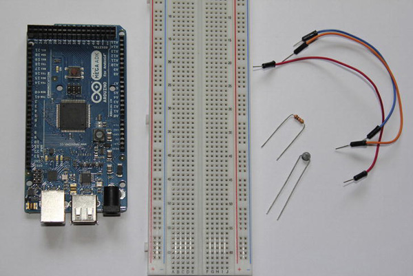
Figure 7-1. Project 8 parts (ADK board, breadboard, wires, 4.7kΩ thermistor, 10kΩ resistor)
Thermistor
A thermistor is a variable resistor whose resistance value is dependent on the ambient temperature. Its name is a composition of the words thermal and resistor. Thermistors are not directional, meaning that it doesn't matter which way you connect them to your circuit, just as with common resistors. They can have a negative or a positive coefficient, which means that their resistance in correspondence to the temperature increases when they have a negative coefficient and that it decreases if they have a positive coefficient. As photoresistors do, they rely on the band theory, described in Chapter 6 in the section on photoresistors. The temperature change has a direct effect on a thermistor's electrons, promoting them into the conductive band and causing a change in conductivity and resistance. Thermistors come in different shapes, but the most common is the leaded disc thermistor which resembles a typical ceramic capacitor. (See Figure 7-2.)

The most important thing to do when choosing a thermistor is to have a look into its datasheet first. The datasheet needs to contain some important details for the temperature calculation. Some datasheets contain lookup tables where each resistance value is mapped to a temperature value. Although you could work with such a table, it is a tedious task to transfer it into your code.
A better approach is to calculate the current temperature with the Steinhart-Hart equation. The following abstract will show you the necessary equations for calculating the temperature. Don't be afraid of the math here. Once you know which values you have to put into the equations, it's fairly easy.
The Steinhart-Hart Equation
The Steinhart-Hart equation describes a model where a semiconductor's resistance is dependent of the current temperature T. The formula looks like this:
![]()
In order to apply this formula you'll need three coefficients—a, b, and c—and, additionally, the current resistance R value of your thermistor. If your thermistor's datasheet contains those values you can work with them just fine, but most of the datasheets only provide a so called B or Beta coefficient. Luckily there is another representation of the Steinhart-Hart equation which works with this B parameter and a pair of temperature T0 and resistance R0 for a specific temperature T.
![]()
The different parameters in this equation are just representations of a, b and c.
a = (1 / T0) - (1 / B)×ln(R0)
b = 1 / B
c = 0
R0 is specified as the resistance at T0 which is usually 298.15 Kelvin and equal to 25° Celsius. The following is a simplified formula of the B parameter equation:
R = R∞ × eB/T
R∞ describes the resistance tending to infinity and can be calculated with:
R∞ = R0 × e-B/T0
Now that you can calculate all necessary values you can rearrange the previous formula to finally calculate the temperature.
![]()
The equations will be applied in the Arduino sketch later on so you will encounter them again later.
The Setup
You'll have to set up a voltage divider circuit to measure the change in voltage when the resistance of the thermistor changes. The composition of the voltage divider depends on the type of thermistor you use. If you are using a negative coefficient thermistor (NTC) your basic circuit setup looks like the one shown in Figure 7-3.

Figure 7-3. NTC thermistor voltage divider
If you are using a positive coefficient thermistor (PTC) you'll need a circuit as shown in Figure 7-4.

Figure 7-4. PTC thermistor voltage divider
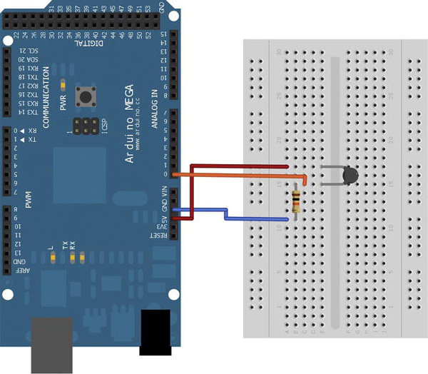
For this project you'll need to see an increase in voltage measured on the analog input pin when the temperature goes up and a decrease in the measured voltage when the temperature goes down. So make sure to build your voltage divider circuit according to the thermistor you use, as shown above. Figure 7-5 shows the project setup for an NTC thermistor.
The Software
The Arduino sketch for this project will use some of the mathematical functions of the Arduino platform. You will use self-written methods to express formulas to calculate the current temperature. The temperature value will be transmitted to the Android device afterward. The Android application will demonstrate how to draw simple shapes and text to the Android device's screen to visualize the measured temperature.
The Arduino Sketch
For the first time you will be writing your own custom methods in an Arduino sketch. Custom methods must be written outside of the mandatory setup and loop method. They can have a return type and input parameters.
Additionally, you will use some of the Arduino platform's mathematical functions. You will need the log and exp function to apply the Steinhart-Hart equation for calculating the temperature. The calculated temperature value needs to be bit-shifted for proper transmission to the Android device. Have a look at the complete Listing 7-1; I describe the details after the listing.
Listing 7-1. Project 8: Arduino Sketch
#include <Max3421e.h>

#include <Usb.h>

#include <AndroidAccessory.h>


#define COMMAND_TEMPERATURE 0x4

#define INPUT_PIN_0 0x0

//-----

//change those values according to your thermistor's datasheet

long r0 = 4700;

long beta = 3980;

//-----


double t0 = 298.15;

long additional_resistor = 10000;

float v_in = 5.0;

double r_inf;

double currentThermistorResistance;


AndroidAccessory acc("Manufacturer",

                     "Model",

                     "Description",

                     "Version",

                     "URI",

                     "Serial");


byte sntmsg[6];


void setup() {

  Serial.begin(19200);

  acc.powerOn();

  sntmsg[0] = COMMAND_TEMPERATURE;

  sntmsg[1] = INPUT_PIN_0;

  r_inf = r0 * (exp((-beta) / t0));

}


void loop() {

  if (acc.isConnected()) {

    int currentADCValue = analogRead(INPUT_PIN_0);
    float voltageMeasured = getCurrentVoltage(currentADCValue);

    double currentThermistorResistance = getCurrentThermistorResistance(voltageMeasured);

    double currentTemperatureInDegrees =

      getCurrentTemperatureInDegrees(currentThermistorResistance);


    // multiply the float value by 10 to retain one value behind the decimal point before

    // converting to an integer for better value transmission

    int convertedValue = currentTemperatureInDegrees * 10;


    sntmsg[2] = (byte) (convertedValue >> 24);

    sntmsg[3] = (byte) (convertedValue >> 16);

    sntmsg[4] = (byte) (convertedValue >> 8);

    sntmsg[5] = (byte) convertedValue;

    acc.write(sntmsg, 6);

    delay(100);

  }

}


// "reverse ADC calculation"

float getCurrentVoltage(int currentADCValue) {

  return v_in * currentADCValue / 1024;

}


// rearranged voltage divider formula for thermistor resistance calculation

double getCurrentThermistorResistance(float voltageMeasured) {

  return ((v_in * additional_resistor) - (voltageMeasured * additional_resistor)) /

    voltageMeasured;

}


//Steinhart-Hart B equation for temperature calculation

double getCurrentTemperatureInDegrees(double currentThermistorResistance) {

  return (beta / log(currentThermistorResistance / r_inf)) - 273.15;

}
Let's have a look at the variables defined at the top of the sketch. The first variables you see here are the definitions for the data protocol. To confirm that temperature data is transmitted, the byte constant COMMAND_TEMPERATURE 0x4 has been chosen. The analog input pin for taking measurements is defined as being INPUT_PIN_0 0x0.
Now the datasheet-specific values are defined:
long r0 = 4700;

long beta = 3980;
I used a 4.7kΩ thermistor in this project, which means that the thermistor's resistance at 25° Celsius (R0) is 4.7kΩ. That's why r0 is defined as 4700. The thermistor's datasheet only defined the B value in my case, which was 3980. Have a look into your thermistor's datasheet and adjust those values if necessary.
Next you'll see some definitions of constant values for calculation purposes:
double t0 = 298.15;

long additional_resistor = 10000;

float v_in = 5.0;
You need the temperature in Kelvin at 25° Celsius (T0) for calculating R∞. Additionally, you need the second resistor value in the voltage divider circuit, which is 10kΩ, and the input voltage to calculate the current resistance of the thermistor.
The last two variables are needed in the B parameter variation of the Steinhart-Hart equation when you calculate the current temperature.
Now let's see what happens in the program flow. In the setup method, you will calculate the value for R∞, as it only needs to be calculated once at the beginning.
r_inf = r0 * (exp((-beta) / t0));
The repeating steps in the loop method can be described as follows:
- Read current ADC value.
- Calculate the actual voltage on the pin from the ADC value.
- Calculate the current thermistor resistance.
- Calculate the current temperature.
- Convert the temperature to an integer number for easier transmission.
- Transmit the data.
Now let's see the detailed description of the single steps.
The analogRead method returns the currently read ADC value. You will use it to calculate the actual voltage applied to the analog input pin. For that purpose you use a self-written custom method:
float getCurrentVoltage(int currentADCValue) {

  return v_in * currentADCValue / 1024;

}
The getCurrentVoltage method takes the currentADCValue as an input parameter and returns the calculated voltage as a float. Since the Arduino platform maps the voltage range of 0V to 5V to 1024 values, you simply multiply the currentADCValue with 5.0V and divide it by 1024 to calculate the current voltage.
Now that you have the measured voltage you can calculate the actual resistance of the thermistor with the self-written method getCurrentThermistorResistance.
double getCurrentThermistorResistance(float voltageMeasured) {

  return ((v_in * additional_resistor) - (voltageMeasured * additional_resistor)) /

    voltageMeasured;

}
The getCurrentThermistorResistance method takes the measured voltage as an input parameter, calculates the resistance, and returns it as a double.
Finally, the most important calculation can be made. To calculate the temperature you use the self-written method getCurrentTemperatureInDegrees.
double getCurrentTemperatureInDegrees(double currentThermistorResistance) {

  return (beta / log(currentThermistorResistance / r_inf)) - 273.15;

}
The method takes the current thermistor resistance as an input parameter. It uses the B parameter variant of the Steinhart-Hart equation to calculate the current temperature in Kelvin. To convert it into degrees Celsius you have to subtract a value of 273.15. The method returns the current temperature in degrees Celsius as a double. The Arduino log function used here is the natural logarithmic function ln used in the formulas above.
The last remaining step before transmitting the data to the Android device is to convert the temperature value for easier transmission. For example, you might have calculated a double value of 22.52 degrees Celsius. Since you are transmitting only bytes you have to convert the value into a non-floating point number. A precision of one number after the decimal point should be sufficient so the conversion is as easy as just multiplying the value by 10, causing the value to be 225.
int convertedValue = currentTemperatureInDegrees * 10;
During the multiplication the decimal point is shifted one position to the right. Since the multiplication also converts the value to a non-floating number, the number after the decimal point is used to round the preceding number up or down before being dropped. So a value of 22.52 would become 225 and a value of 22.56 would become 226.
Now that you have an integer value, you need the bit-shifting technique again to convert it into a four-byte array.
sntmsg[2] = (byte) (convertedValue >> 24);

sntmsg[3] = (byte) (convertedValue >> 16);

sntmsg[4] = (byte) (convertedValue >> 8);

sntmsg[5] = (byte) convertedValue;

acc.write(sntmsg, 6);
That's it for the Arduino part, so let's have a look at the Android application.
The Android Application
As you already know, the first steps in the Android application are to establish the communication with the ADK board, reading the transmitted data and converting it back to its original integer value. Once you've done that you will visualize the current temperature by drawing 2D graphics onto the device's screen. This application will show you how to use some of the 2D graphics classes and methods to draw simple shapes to the screen's canvas. Listing 7-2 shows a snippet of the current project's activity with the emphasis on the new and important parts.
Listing 7-2. Project 8: ProjectEightActivity.java
package project.eight.adk;


import …;


public class ProjectEightActivity extends Activity {


    …


    private static final byte COMMAND_TEMPERATURE = 0x4;

    private static final byte TARGET_PIN = 0x0;


    private TemperatureView temperatureView;


    /** Called when the activity is first created. */

    @Override

    public void onCreate(Bundle savedInstanceState) {
        super.onCreate(savedInstanceState);


        …


        setContentView(R.layout.main);

        temperatureView = (TemperatureView) findViewById(R.id.temperature_view);

    }


    /**

     * Called when the activity is resumed from its paused state and immediately

     * after onCreate().

     */

    @Override

    public void onResume() {

        super.onResume();

        …

    }


    /** Called when the activity is paused by the system. */

    @Override

    public void onPause() {

        super.onPause();

        closeAccessory();

    }


    /**

     * Called when the activity is no longer needed prior to being removed from

     * the activity stack.

     */

    @Override

    public void onDestroy() {

        super.onDestroy();

        unregisterReceiver(mUsbReceiver);

    }


    private final BroadcastReceiver mUsbReceiver = new BroadcastReceiver() {

        @Override

        public void onReceive(Context context, Intent intent) {

            …

        }

    };


    private void openAccessory(UsbAccessory accessory) {

        mFileDescriptor = mUsbManager.openAccessory(accessory);

        if (mFileDescriptor != null) {

            mAccessory = accessory;

            FileDescriptor fd = mFileDescriptor.getFileDescriptor();

            mInputStream = new FileInputStream(fd);

            mOutputStream = new FileOutputStream(fd);

            Thread thread = new Thread(null, commRunnable, TAG);

            thread.start();

            Log.d(TAG, "accessory opened");
        } else {

            Log.d(TAG, "accessory open fail");

        }

    }


    private void closeAccessory() {

        try {

            if (mFileDescriptor != null) {

                mFileDescriptor.close();

            }

        } catch (IOException e) {

        } finally {

            mFileDescriptor = null;

            mAccessory = null;

        }

    }


    Runnable commRunnable = new Runnable() {


        @Override

        public void run() {

            int ret = 0;

            byte[] buffer = new byte[6];


            while (ret >= 0) {

                try {

                    ret = mInputStream.read(buffer);

                } catch (IOException e) {

                    Log.e(TAG, "IOException", e);

                    break;

                }


                switch (buffer[0]) {

                case COMMAND_TEMPERATURE:

                    if (buffer[1] == TARGET_PIN) {

                        final float temperatureValue = (((buffer[2] & 0xFF) << 24)

                                                    + ((buffer[3] & 0xFF) << 16)

                                                    + ((buffer[4] & 0xFF) << 8)

                                                    + (buffer[5] & 0xFF))

                                                    / 10;

                        runOnUiThread(new Runnable() {


                            @Override

                            public void run() {

                                temperatureView.setCurrentTemperature(temperatureValue);

                            }

                        });

                    }

                    break;


                default:
                    Log.d(TAG, "unknown msg: " + buffer[0]);

                    break;

                }

            }

        }

    };

}
First have a look at the variable definitions. The first two message bytes have to match the bytes defined in the Arduino sketch, so you define them as follows:
private static final byte COMMAND_TEMPERATURE = 0x4;

private static final byte TARGET_PIN = 0x0;
Then you can see another variable of the type TemperatureView.
private TemperatureView temperatureView;
TemperatureView, as the name implies, is a self-written custom View which extends the Android system View class. We will have a look into that class soon, but first let's continue with the remaining code of the activity class.
After reading the received message, you have to convert the byte array back into its original integer value. You just reverse the bit-shifting done in the Arduino part to get the integer value. Additionally you need to divide the integer number by ten to get the floating-point value you initially calculated.
final float temperatureValue = (((buffer[2] & 0xFF) << 24)

                                + ((buffer[3] & 0xFF) << 16)

                                + ((buffer[4] & 0xFF) << 8)

                                + (buffer[5] & 0xFF))

                                / 10;
A received value of 225 would now be converted to 22.5.
The last thing to do is to transfer the value to the TemperatureView so that you can draw a temperature visualization on its canvas.
runOnUiThread(new Runnable() {


    @Override

    public void run() {

        temperatureView.setCurrentTemperature(temperatureValue);

    }

});
Remember that you should update UI elements only on the UI thread. You have to set the temperature value on the TemperatureView within the runOnUIThread method because it will invalidate itself afterward to be redrawn.
The 2D drawings are implemented in the TemperatureView class itself so have a look at the complete Listing 7-3 first.
Listing 7-3. Project 8: TemperatureView.java
package project.eight.adk;


import android.content.Context;

import android.content.res.TypedArray;
import android.graphics.Canvas;

import android.graphics.Color;

import android.graphics.Paint;

import android.graphics.RectF;

import android.util.AttributeSet;

import android.view.View;


public class TemperatureView extends View {

    private float currentTemperature;

    private Paint textPaint = new Paint();

    private Paint thermometerPaint = new Paint();

    private RectF thermometerOval = new RectF();

    private RectF thermometerRect = new RectF();


    private int availableWidth;

    private int availableHeight;


    private final float deviceDensity;


    private int ovalLeftBorder;

    private int ovalTopBorder;

    private int ovalRightBorder;

    private int ovalBottomBorder;


    private int rectLeftBorder;

    private int rectTopBorder;

    private int rectRightBorder;

    private int rectBottomBorder;


    public TemperatureView(Context context, AttributeSet attrs) {

        super(context, attrs);

        textPaint.setColor(Color.BLACK);

        thermometerPaint.setColor(Color.RED);

        deviceDensity = getResources().getDisplayMetrics().density;

        TypedArray attributeArray = context.obtainStyledAttributes(attrs,

            R.styleable.temperature_view_attributes);

        int textSize = attributeArray.getInt(

            R.styleable.temperature_view_attributes_textSize, 18);

        textSize = (int) (textSize * deviceDensity + 0.5f);

        textPaint.setTextSize(textSize);

    }


    @Override

    protected void onMeasure(int widthMeasureSpec, int heightMeasureSpec) {

        super.onMeasure(widthMeasureSpec, heightMeasureSpec);

        availableWidth = getMeasuredWidth();

        availableHeight = getMeasuredHeight();


        ovalLeftBorder = (availableWidth / 2) - (availableWidth / 10);

        ovalTopBorder = availableHeight - (availableHeight / 10) - (availableWidth / 5);

        ovalRightBorder = (availableWidth / 2) + (availableWidth / 10);

        ovalBottomBorder = availableHeight - (availableHeight / 10);
        //setup oval with its position centered horizontally and at the bottom of the screen

        thermometerOval.set(ovalLeftBorder, ovalTopBorder, ovalRightBorder, ovalBottomBorder);


        rectLeftBorder = (availableWidth / 2) - (availableWidth / 15);

        rectRightBorder = (availableWidth / 2) + (availableWidth / 15);

        rectBottomBorder = ovalBottomBorder - ((ovalBottomBorder - ovalTopBorder) / 2);

    }


    public void setCurrentTemperature(float currentTemperature) {

        this.currentTemperature = currentTemperature;

        //only draw a thermometer in the range of -50 to 50 degrees celsius

        float thermometerRectTop = currentTemperature + 50;

        if(thermometerRectTop < 0) {

            thermometerRectTop = 0;

        } else if(thermometerRectTop > 100){

            thermometerRectTop = 100;

        }

        rectTopBorder = (int) (rectBottomBorder - (thermometerRectTop *

            (availableHeight / 140)));

        //update rect borders

        thermometerRect.set(rectLeftBorder, rectTopBorder, rectRightBorder, rectBottomBorder);

        invalidate();

    }


    @Override

    protected void onDraw(Canvas canvas) {

        super.onDraw(canvas);

        //draw shapes

        canvas.drawOval(thermometerOval, thermometerPaint);

        canvas.drawRect(thermometerRect, thermometerPaint);

        //draw text in the upper left corner

        canvas.drawText(getContext().getString(

            R.string.temperature_value, currentTemperature),

            availableWidth / 10, availableHeight / 10, textPaint);

    }

}
Have a look at the variables first. The currentTemperature variable will be set by the activity containing the TemperatureView, as you've seen before.
private float currentTemperature;
Next you can see two Paint references. A Paint object defines things like color, size, strokewidth, and so on. When you are drawing shapes or text you can provide a Paint object for the corresponding method call for refining the drawing result. You'll use two Paint objects, one for the textual visualization and one for the shapes you will draw later on.
private Paint textPaint = new Paint();

private Paint thermometerPaint = new Paint();
The RectF objects can be understood as bounding boxes that are used to define the bounds of a shape.
You'll be drawing a thermometer, so you will draw two different shapes: an oval for the basis and a rectangle for the temperature bar (see Figure 7-6).
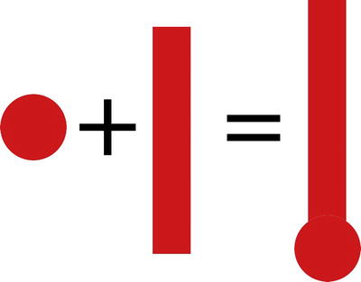
Figure 7-6. 2D shapes to create a thermometer (oval + rect = thermometer)
The next two variables will contain the View's width and height. They are used to calculate the position where you will draw the thermometer.
private int availableWidth;

private int availableHeight;
To be able to adjust the text size to your device's screen properties, you'll have to determine your screen density (but more on that later).
private final float deviceDensity;
The 2D graphics you will draw to depict a thermometer have defined boundaries. Those boundaries need to be calculated dynamically to fit to any screen size so you will save them in global variables as well.
private int ovalLeftBorder;

private int ovalTopBorder;

private int ovalRightBorder;

private int ovalBottomBorder;


private int rectLeftBorder;

private int rectTopBorder;

private int rectRightBorder;

private int rectBottomBorder;
That's it for the variables. Now we will have a look at the method implementations, starting with the constructor of the TemperatureView.
public TemperatureView(Context context, AttributeSet attrs) {

    super(context, attrs);

    textPaint.setColor(Color.BLACK);

    thermometerPaint.setColor(Color.RED);

    deviceDensity = getResources().getDisplayMetrics().density;

    TypedArray attributeArray = context.obtainStyledAttributes(attrs,

        R.styleable.temperature_view_attributes);

    int textSize = attributeArray.getInt(

        R.styleable.temperature_view_attributes_textSize, 18);

    textSize = (int) (textSize * deviceDensity + 0.5f);

    textPaint.setTextSize(textSize);

}
If you want to embed your custom View into an XML layout file you need to implement a constructor that takes not only a Context object but also an AttributeSet. Those will be set by the system once the View is inflated. The AttributeSet contains the XML definitions you can make such as width and height and even self-defined attributes. You also need to call the parent View's constructor for the attributes to be set properly. The constructor is also used to set up the Paint objects. This is only needed once, so you can set the colors and the text size in here.
When defining the text size, you have to consider that devices have different screen properties. They can come in different sizes from small to extra large, and each size can have a different density, as well, ranging from low density to extra-high density. The size describes the actual physical size measured as the screen's diagonal. The density describes the number of pixels in a defined physical area, mostly expressed as dots per inch (dpi). If you were to define a fixed pixel size for the text, it would show very differently across devices having the same size. It could be rendered very large on devices with a low density, whereas other devices of the same size would render it very small because they have a higher density.
![]() Note To learn more about screen sizes and densities visit the Android Developer Guide at
Note To learn more about screen sizes and densities visit the Android Developer Guide at http://developer.android.com/guide/practices/screens_support.html.
To address that issue you'll have to do several things here. First, you'll have to determine the device's density to calculate the actual pixel size you need to set so that the text looks uniform across devices.
deviceDensity = getResources().getDisplayMetrics().density;
Now that you have the density, you only need the relative size of the text to calculate the actual pixel size. When writing your own View element you can also define custom attributes for that view. In this example you will define the attribute textSize for the TemperatureView. In order to do that you'll have to create a new file that defines all custom attributes the TemperatureView can have. Create an XML file called attributes.xml in res/values. The name of the file is not restricted, so you can choose to call it whatever you like; just make sure that it ends with .xml. Inside of this XML file you'll have to define the attribute as shown in Listing 7-4.
Listing 7-4. Project 8: attributes.xml
<?xml version="1.0" encoding="utf-8"?>

<resources>

    <declare-styleable name="temperature_view_attributes">

        <attr name="textSize" format="integer"/>

    </declare-styleable>

</resources>
Next, you'll need to add the TemperatureView to your layout and set its textSize attribute. If you use your own custom views in an XML layout file you have to define them with their fully qualified class name, which is their package name plus their class name. The main.xml layout file for this project looks like Listing 7-5.
Listing 7-5. Project 8: main.xml
<?xml version="1.0" encoding="utf-8"?>

<project.eight.adk.TemperatureView

    xmlns:android="http://schemas.android.com/apk/res/android"

    xmlns:temperatureview="http://schemas.android.com/apk/res/project.eight.adk"

    android:id="@+id/custom_view"

    android:layout_width="fill_parent"

    android:layout_height="fill_parent"

    android:background="#FFFFFF"

    temperatureview:textSize=”18”>

</project.eight.adk.TemperatureView
Since you add not only system attributes but also your own attribute, you'll have to define your own namespace in addition to the standard system namespace.
xmlns:temperatureview="http://schemas.android.com/apk/res/project.eight.adk"
To define your own namespace you specify a name, as done here with temperatureview, and add the schema location. The schema location of the custom attribute you added earlier is http://schemas.android.com/apk/res/project.eight.adk. The important last part of the schema location reflects your package structure. Once the schema is added, you can define the custom attribute textSize by adding your namespace-name as a prefix.
temperatureview:textSize=”18”>
You have successfully configured the custom attribute textSize now. Let's see how you can access its value when you initialize the TemperatureView.
TypedArray attributeArray = context.obtainStyledAttributes(attrs,

    R.styleable.temperature_view_attributes);

int textSize = attributeArray.getInt(R.styleable.temperature_view_attributes_textSize, 18);
First, you'll have to get a reference to a TypedArray object that holds all attributes for a given styleable attribute set. To do that you call the obtainStyledAttributes method on the current Context object. This method takes two parameters, the current view's AttributeSet and the styleable attribute set you are interested in. Within the returned TypedArray you will find your textSize attribute. To access it, you call the type specific getter method on the TypedArray and provide the attribute's name you're interested in, along with a default value if that attribute cannot be found.
Finally you have the defined text size you can use to calculate the actual pixel size you need for your device's density.
textSize = (int) (textSize * deviceDensity + 0.5f);
That's it for the constructor of the TemperatureView. Next up is the onMeasure method.
@Override

protected void onMeasure(int widthMeasureSpec, int heightMeasureSpec) {

    super.onMeasure(widthMeasureSpec, heightMeasureSpec);

    availableWidth = getMeasuredWidth();

    availableHeight = getMeasuredHeight();


    ovalLeftBorder = (availableWidth / 2) - (availableWidth / 10);

    ovalTopBorder = availableHeight - (availableHeight / 10) - (availableWidth / 5);

    ovalRightBorder = (availableWidth / 2) + (availableWidth / 10);

    ovalBottomBorder = availableHeight - (availableHeight / 10);

    //setup oval with its position centered horizontally and at the bottom of the screen

    thermometerOval.set(ovalLeftBorder, ovalTopBorder, ovalRightBorder, ovalBottomBorder);


    rectLeftBorder = (availableWidth / 2) - (availableWidth / 15);

    rectRightBorder = (availableWidth / 2) + (availableWidth / 15);

    rectBottomBorder = ovalBottomBorder - ((ovalBottomBorder - ovalTopBorder) / 2);

}
The onMeasure method is inherited from the View system class. It is called by the system to calculate the necessary size to display the View. It's overridden here to get the current width and height of the View so that the shapes can be drawn in proper proportion later on. Note that it is important to also call the parent's onMeasure method or the system will throw an IllegalStateException. Once you have the width and height you can already define the bounding box for the oval shape because it will not change later on. You can also calculate three of the four borders of the rectangle shape. The only border that depends on the current temperature is the top border, so that will be calculated later. The calculations for the borders define shapes that will look proportional on each device.
To update the measured temperature value for visualization, you write a setter method called setCurrentTemperature, which takes the current temperature as a parameter. The setCurrentTemperature method is not just a simple variable setter. It is also used here to update the bounding box for the thermometer bar's rectangle and for invalidating the view so that it gets redrawn.
public void setCurrentTemperature(float currentTemperature) {

    this.currentTemperature = currentTemperature;

    //only draw a thermometer in the range of -50 to 50 degrees celsius

    float thermometerRectTop = currentTemperature + 50;

    if(thermometerRectTop < 0) {

        thermometerRectTop = 0;

    } else if(thermometerRectTop > 100){

        thermometerRectTop = 100;

    }

    rectTopBorder = (int) (rectBottomBorder - (thermometerRectTop *

        (availableHeight / 140)));

    //update rect borders

    thermometerRect.set(rectLeftBorder, rectTopBorder, rectRightBorder, rectBottomBorder);

    invalidate();

}
After updating the borders of the rectangle you need to invalidate the TemperatureView. The invalidate method, inherited from the TemperatureView's super class View, tells the system that this particular view element is invalid and needs to be redrawn.
The last method is the actual method responsible for the 2D graphical drawing. The onDraw method is called on a View each time it needs to be updated. You can tell the system that it needs redrawing by calling the invalidate method as was done in the setCurrentTemperature method. Let's have a look into its implementation.
@Override

protected void onDraw(Canvas canvas) {

    super.onDraw(canvas);


    //draw shapes

    canvas.drawOval(thermometerOval, thermometerPaint);

    canvas.drawRect(thermometerRect, thermometerPaint);


    //draw text in the upper left corner

    canvas.drawText(getContext().getString(

        R.string.temperature_value, currentTemperature),

        availableWidth / 10, availableHeight / 10, textPaint);

}
When the system calls the onDraw method it provides a Canvas object associated with the View. The Canvas object is used for drawing on its surface. The order of the draw method calls is important. You can think of it as an actual real-life canvas on which you would draw layer over layer. Here you can see that first an oval with its predefined RectF and Paint object is drawn. Next, the rectangle symbolizing the thermometer bar is drawn. At last the textual visualization is drawn by defining the text to draw, its coordinates with the origin being the top-left corner and its associated Paint object. That's it for the coding part.
After all those calculations, it is finally time to see if your self-built thermometer works. Deploy your applications and you should see an increase in temperature if you warm up the thermistor with your fingertips. The final result should look like Figure 7-7.
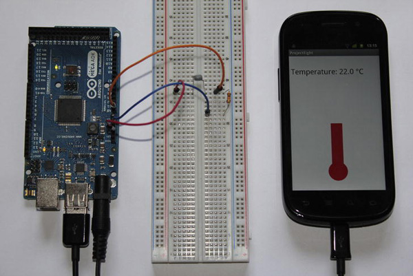
Figure 7-7. Project 8: Final result
Summary
In this chapter you learned how to build your own thermometer. You also learned the basics about thermistors and how to calculate the ambient temperature with the help of the Steinhart-Hart equation. For visualization purposes, you wrote your own custom UI element. You also used 2D graphical drawings to draw a virtual thermometer along with a textual representation of the currently measured temperature.