
Lighting and Materials
The programming team can help the art team achieve the look they desire for a game through the application of lighting and material models. Many techniques over the years have been developed to give games a specific style; Jet Grind Radio (Jet Set Radio outside North America), which was published in the year 2000, was one such game. Jet Grind Radio was famous for its cell-shaded graphical style which set it apart from the competition at the time.
The style of Jet Grind Radio was all the more impressive given that it was developed on a platform which did not have vertex and fragment shaders. Special lighting and material effects have become much more prevalent in video games over the last ten years as consumer hardware has advanced to a point which has made real-time shaders a possibility. These features are now also prevalent on mobile devices, and flexibility of shaders has opened up the use of advanced graphical techniques to game developers.
In this chapter, we’re going to be looking at the basic lighting and material techniques which are used as a foundation for the more advanced effects. The basic lights and materials in this chapter are a recreation of the fixed function lights and materials from OpenGL ES 1.0.
Note OpenGL ES 2.0 does not have any inbuilt support for lighting; it is up to the programmer to implement the model they desire using shaders.
To begin, we’ll take a look at what how light is defined to a programmer and how light interacts with our game entities via materials.
A Basic Lighting and Material Model
Light in the natural world is a complex phenomenon. Fortunately, as game developers we do not have to model light with physical reality; we instead use a model which approximates what light does and how it interacts with the objects in our scene.
At the most basic level, whether we are dealing with lights in a vertex or fragment shader, our light sources will eventually boil down to having a direction and a color which affect the output color of our object using some form of equation.
The light’s properties make up one set of inputs for our lighting equations; another set of inputs will be the properties of the object itself. We refer to these object properties as materials. When discussing materials, we say that we are applying materials to objects.
A material definition in a modern game engine includes the shader program to be used to shade the model, the textures to be applied, as well as any other special effects and render states which are necessary for proper rendering of the object.
This is the brief overview of lighting, and you won’t be surprised to learn that the actual implementation of the model is slightly more complex. Our lights and materials are going to be used to calculate three different components of light: ambient, diffuse, and specular. In this chapter, we are going to cover each of these components and look at the effects of each.
Once we have looked at the components of the lighting equation, we will look at three different representations of light sources in our engine. These will be directional lights, positional lights, and spotlights.
Per-Vertex or Per-Fragment Shading
The shading model which was used in OpenGL ES 1.0 is called the Blinn-Phong shading model. It is named after Jim Blinn and Bui Tuong Phong. Phong described his lighting model in 1973, and this was later modified by Blinn, giving rise to the name.
The model itself describes the equations we will use in this chapter to calculate the ambient, diffuse, and specular components of the color to be applied to the object. Another aspect of the model which we must consider is how accurate we would like the computations to be. If we calculate the color of the result of the interactions among the light, the surface, and the material in the vertex shader, the color will be stored in a varying and then interpolated across the rest of the polygon. This form of interpolating color is known as Gouraud shading, again named after the author of the technique, Henri Gouraud.
This technique can give acceptable results, but it is often possible to easily see the edges of polygons. An alternative form of interpolation is the Phong shading model, which was described by Bui Tuong Phong, along with the rest of his shading model technique. This form of interpolation involves interpolating the normal of the vertex across the surface of the fragment and calculating lighting color for each individual pixel in the fragment shader. This gives much better results but is obviously much more computationally expensive.
Fortunately for us, the equations of lighting are the same in both cases, and as we have a very simple scene in comparison to commercial games, we will be using the Blinn-Phong lighting model and Phong shading to give us the best results.
Before we get on with the task of implementing the lighting in our scene, we have to create a class which can represent a material.
Representing Materials
The Material class will be used to store all of the information which is relevant to the final appearance of the surfaces of the objects present in our scene. This includes any shaders, textures, and the colors which we will use to represent the separate sections of the lighting equation. Listing 9-1 describes the Material class. We haven’t yet covered what the fields of this class will be used for, so don’t worry about them for now.
Listing 9-1. The Material Class Declaration. Material.h
class Material
{
       private:
              Shader*       m_pShader;
              Texture*      m_pTexture;

              Vector4       m_ambientColor;
              Vector4       m_diffuseColor;
              Vector4       m_specularColor;
              float         m_specularExponent;

public:
       Material()
              :      m_pShader(NULL)
              ,      m_pTexture(NULL)
              ,      m_specularExponent(0.0f)
       {

       }

       ∼Material()
       {

       }

       void SetShader(Shader* pShader)
       {
              m_pShader = pShader;
       }

       Shader* GetShader() const
       {
              return m_pShader;
       }

       void SetTexture(Texture* pTexture)
       {
              m_pTexture = pTexture;
       }

       Texture* GetTexture() const
       {
              return m_pTexture;
       }

       void SetAmbientColor(Vector4 ambientColor)
       {
              m_ambientColor = ambientColor;
       }

       const Vector4& GetAmbientColor() const
       {
              return m_ambientColor;
       }

       void SetDiffuseColor(Vector4 diffuseColor)
       {
              m_diffuseColor = diffuseColor;
       }

       const Vector4& GetDiffuseColor() const
       {
              return m_diffuseColor;
       }

       void SetSpecularColor(Vector4 specularColor)
       {
              m_specularColor = specularColor;
       }

       const Vector4& GetSpecularColor() const
       {
              return m_specularColor;
       }

       void SetSpecularExponent(float specularExponent)
       {
              m_specularExponent = specularExponent;
       }

       const float GetSpecularExponent() const
       {
              return m_specularExponent;
       }
};
As you can see, our Material class is just a container to store some data which we can associate with an object. We do this by adding it to our Renderable class. Listing 9-2 shows our new Renderable class with a Material in place of the Shader pointer and color Vector4 field which were there previously.
Listing 9-2. Adding a Material to Renderable. Renderable.h
class Renderable
{
private:
       Geometry*     m_pGeometry;
 Material* m_pMaterial;
       Transform     m_transform;

       Vector3       m_min;
       Vector3       m_max;
       bool          m_useBounds;

public:
       Renderable();
       ∼Renderable();

       void          SetGeometry(Geometry* pGeometry);
       Geometry*     GetGeometry();

 void SetMaterial(Material* pMaterial);
 Material* GetMaterial();

       Transform&    GetTransform()       { return m_transform; }

       void                 SetBoundMin(const Vector3& min)    { m_min = min; }
       const Vector3&       GetBoundMin() const                { return m_min; }

       void                 SetBoundMax(const Vector3& max)    { m_max = max; }
       const Vector3&       GetBoundMax() const                { return m_max; }

       void                 SetUseBounds(bool enabled)         { m_useBounds = enabled; }
       bool                 GetUseBounds() const               { return m_useBounds; }

       bool                 IsInitialized() const
       {
 return m_pGeometry
&&
m_pMaterial;
       }
};

inline Renderable::Renderable()
       :      m_pGeometry(NULL)
 , m_pMaterial(NULL)
{

}

inline Renderable::∼Renderable()
{

}

inline void Renderable::SetGeometry(Geometry* pGeometry)
{
       m_pGeometry = pGeometry;
}

inline Geometry* Renderable::GetGeometry()
{
       return m_pGeometry;
}

inline void Renderable::SetMaterial(Material* pMaterial)
{
 m_pMaterial = pMaterial;
}

inline Material* Renderable::GetMaterial()
{
 return m_pMaterial;
}
Now that we have a class which can store material properties for our Renderables, we will look at how we can use these in Shaders which add light to our scene.
The ambient component of the lighting model is used to approximate the background light which will be present in our scene. You can think of this much like daylight in a room with windows.
Nothing in the room is being lit directly by a light source; however, everything has light bouncing off of it. This is because the light from the sun is powerful enough that it can bounce off of many objects yet still carry on and light many more. Once the sun goes down, everything is much darker, as there is much less ambient light bouncing around.
In this sense, ambient light is treated much like a base level of lighting to ensure that objects in the scene do not appear to be completely black. The equation for the ambient lighting component is very straightforward.
final color = ambient light color × ambient color
The current rendering we have been using in TransformShader so far has effectively been the equivalent of having an ambient light value of (1, 1, 1, 1), which specifies that our object should be lit fully by ambient lighting; Figure 9-1 shows how the game currently renders with no lighting present.
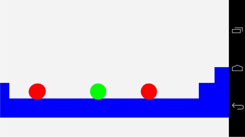
Figure 9-1. An unlit scene from Droid Runner
We’ll change this now by adding a new shader. Listing 9-3 shows the TransformAmbientShader class.
Listing 9-3. The TransformAmbientShader Class Declaration. TransformAmbientShader.h
class TransformAmbientShader
       :      public Shader
{
private:
       GLint  m_transformUniformHandle;
       GLint  m_positionAttributeHandle;
       GLint  m_colorUniformHandle;
       GLint  m_ambientLightUniformHandle;

public:
       TransformAmbientShader();
       virtual ∼TransformAmbientShader();

       virtual void Link();
       virtual void Setup(Renderable& renderable);
};
Our TransformAmbientShader class is almost identical to our TransformShader; the only addition is a new field to store the handle to the ambient light uniform.
The constructor for TransformAmbientShader contains the new GLSL code for our new shader. The fragment shader contains a new uniform, u_vAmbientLight. This uniform is a vec4 and contains the ambient light constant. This constant is multiplied with the fragment color to determine the ambient color for the fragment which is stored into gl_FragColor. Listing 9-4 shows the new GLSL code.
Listing 9-4. TransformAmbientShader's Constructor. TransformAmbientShader.cpp
TransformAmbientShader::TransformAmbientShader()
{
       m_vertexShaderCode =
              "uniform mat4 u_mModel;
"
              "attribute vec4 a_vPosition;
"
              "void main(){
"
              "    gl_Position = u_mModel * a_vPosition;
"
              "}
";

       m_fragmentShaderCode =
              "precision mediump float;
"
              "
"
              "uniform vec4 u_vColor;
"
              "uniform vec4 u_vAmbientLight;
"
              "
"
              "void main(){
"
              "    gl_FragColor = u_vAmbientLight * u_vColor;
"
              "}
";
}
We need to obtain the handle to the new uniform, and we do this in TransformAmbientShader::Link, shown in Listing 9-5.
Listing 9-5. TransformAmbientShader::Link . TransformAmbientShader.cpp
void TransformAmbientShader::Link()
{
       Shader::Link();
       m_transformUniformHandle            = glGetUniformLocation(m_programId, "u_mModel");
       m_positionAttributeHandle          = glGetAttribLocation(m_programId, "a_vPosition");
       m_colorUniformHandle               = glGetUniformLocation(m_programId, "u_vColor");
       m_ambientLightUniformHandle        = glGetUniformLocation(m_programId, "u_vAmbientLight");
}
This new Shader’s Setup method is also similar to that of TransformShader. Only the lines required to set up the ambient light color are new. Listing 9-6 highlights the changes.
Listing 9-6. TransformAmbientShader::Setup . TransformAmbientShader.cpp
void TransformAmbientShader::Setup(Renderable& renderable)
{
       Geometry* pGeometry = renderable.GetGeometry();
       if (pGeometry)
       {
              Shader::Setup(renderable);
              Renderer& renderer = Renderer::GetSingleton();
              const Matrix4& viewMatrix = renderer.GetViewMatrix();
              const Matrix4& projectionMatrix = renderer.GetProjectionMatrix();
              Matrix4 modelViewMatrix;
              renderable.GetTransform().GetMatrix().Multiply(viewMatrix, modelViewMatrix);
              Matrix4 modelViewProjectionMatrix;
              modelViewMatrix.Multiply(projectionMatrix, modelViewProjectionMatrix);
              glUniformMatrix4fv(m_transformUniformHandle, 1, false, modelViewProjectionMatrix.m_m);
              glVertexAttribPointer(
                     m_positionAttributeHandle,
                     pGeometry->GetNumVertexPositionElements(),
                     GL_FLOAT,
                     GL_FALSE,
                     pGeometry->GetVertexStride(),
                     pGeometry->GetVertexBuffer());
              glEnableVertexAttribArray(m_positionAttributeHandle);
              const Vector4& color = renderable.GetMaterial()->GetAmbientColor();
              glUniform4f(m_colorUniformHandle, color.m_x, color.m_y, color.m_z, color.m_w);
 const Vector4
&
ambientLightColor = renderer.GetAmbientLightColor();
 glUniform4f(m_ambientLightUniformHandle,
 ambientLightColor.m_x,
 ambientLightColor.m_y,
 ambientLightColor.m_z,
 ambientLightColor.m_w);
       }
}
This listing shows that we must also add some new methods to our Renderer. Listing 9-7 shows this minor addition; simply add a new private Vector4 field to the Renderer class and also add methods to set and get the values.
Listing 9-7. Adding m_ambientLightColor to Renderer. Renderer.h
class Renderer
       :      public Task
       ,      public EventHandler
       ,      public Singleton<Renderer>
{
public:
       enum FrustumParameters
       {
              TOP,
              BOTTOM,
              RIGHT,
              LEFT,
              NEAR,
              FAR,
              NUM_PARAMS
       };

private:
       android_app*         m_pState;
       EGLDisplay           m_display;
       EGLContext           m_context;
       EGLSurface           m_surface;
       int                  m_width;
       int                  m_height;
       bool                 m_initialized;
       bool                 m_paused;

       typedef std::vector<Shader*>             ShaderVector;
       typedef ShaderVector::iterator           ShaderVectorIterator;

       typedef std::vector<Texture*>            TextureVector;
       typedef TextureVector::iterator          TextureVectorIterator;

       typedef std::vector<Renderable*>         RenderableVector;
       typedef RenderableVector::iterator       RenderableVectorIterator;

       RenderableVector     m_renderables;
       TextureVector        m_textures;
       ShaderVector         m_shaders;

       float                m_frustumParameters[NUM_PARAMS];

       Matrix4              m_cameraMatrix;
       Matrix4              m_viewMatrix;
       Matrix4              m_projectionMatrix;

       void Draw(Renderable* pRenderable);
       void BuildFrustumPlanes(Plane frustumPlanes[]);
       bool ShouldDraw(Renderable* pRenderable, Plane frustumPlanes[]) const;

 Vector4 m_ambientLightColor;
public:
       explicit Renderer(android_app* pState, const unsigned int priority);
       virtual ∼Renderer();
       void Init();
       void Destroy();

       void AddRenderable(Renderable* pRenderable);
       void AddShader(Shader* pShader);
       void RemoveShader(Shader* pShader);

       void AddTexture(Texture* pTexture);
       void RemoveTexture(Texture* pTexture);

       // From Task
       virtual bool  Start();
       virtual void  OnSuspend();
       virtual void  Update();
       virtual void  OnResume();
       virtual void  Stop();

       virtual void  HandleEvent(Event* event);
       bool IsInitialized() { return m_initialized; }
       void                 SetCameraMatrix(const Matrix4& cameraMatrix)
       {
              m_cameraMatrix = cameraMatrix;
       }

       const Matrix4&       GetCameraMatrix() const     { return m_cameraMatrix; }

       void                 SetViewMatrix(const Matrix4& viewMatrix)
       {
              m_viewMatrix = viewMatrix;
       }
       const Matrix4&       GetViewMatrix() const       { return m_viewMatrix; }

       void                 SetFrustum(const float frustumParameters[]);
       const Matrix4&       GetProjectionMatrix() const { return m_projectionMatrix; }

       int                  GetWidth() const            { return m_width; }
       int                  GetHeight() const           { return m_height; }

 void SetAmbientLightColor(const Vector4&
ambientLightColor)
 {
 m_ambientLightColor = ambientLightColor;
 }
 const Vector4&
GetAmbientLightColor() const
 {
 return m_ambientLightColor;
 }
};
Figure 9-2 shows the state of the game with the ambient lighting being applied to the Renderables.
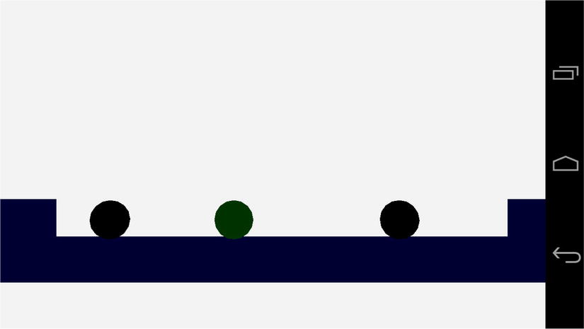
Figure 9-2. The ambient lit scene
As Figure 9-2 shows, an ambient light level of 0.2f for each color component means that our objects are almost black. It’s almost impossible to make out any shade of red on the AI enemies, but the player does have a slight shade of green. The crates are also very slightly blue. This is ideal for our scene, as we will see when we add more color.
Before we move onto the next element in the lighting equation, we must update our Geometry. The diffuse and specular components of the lighting equation need to know in which direction the polygons in our models are facing. We can do this by supplying a normal vector into our shader along with each vertex.
Vertex Normals
We have come across normal vectors a few times so far in this book. If you recall, a normal vector is a vector which is a single unit long and is used to show a direction rather than represent a displacement.
We can work out the normal for a polygon using the plane equation. Since we are always dealing with flat triangles when developing OpenGL ES 2.0 games for Android, we can use the three points of the triangle to generate the surface normal for the triangle. The math for this process is covered in Appendix D, along with the listing of the Plane class and its methods.
Fortunately, all of our models are generally exported from 3D modeling packages. These 3D modeling packages are usually more than capable of generating and exporting the surface normals for any models which we are creating. For this book I have been using the free modeling package, Blender, which you can obtain from www.blender.org .
Given that we will be exporting the vertex normals for our meshes from a 3D package, we should look at how we will represent this data in code. Listing 9-8 shows the updates which are needed in the Geometry class to support vertex normals.
Listing 9-8. Updating Geometry to Handle Vertex Normals. Geometry.h
class Geometry
{
private:
       static const unsigned int NAME_MAX_LENGTH = 16;
       char   m_name[NAME_MAX_LENGTH];
       int    m_numVertices;
       int    m_numIndices;
       void*  m_pVertices;
       void*  m_pIndices;

       int    m_numVertexPositionElements;
       int m_numNormalPositionElements;
       int    m_numTexCoordElements;
       int    m_vertexStride;

public:
       Geometry();
       virtual ∼Geometry();

       void   SetName(const char* name)                 { strcpy(m_name, name); }
       void   SetNumVertices(const int numVertices)     { m_numVertices = numVertices; }
       void   SetNumIndices(const int numIndices)       { m_numIndices = numIndices; }

       const char*   GetName() const                    { return m_name; }

       const int     GetNumVertices() const             { return m_numVertices; }
       const int     GetNumIndices() const              { return m_numIndices; }

       void*         GetVertexBuffer() const            { return m_pVertices; }
       void*         GetIndexBuffer() const             { return m_pIndices; }

       void          SetVertexBuffer(void* pVertices)   { m_pVertices = pVertices; }
       void          SetIndexBuffer(void* pIndices)     { m_pIndices = pIndices; }

       void          SetNumVertexPositionElements(const int numVertexPositionElements)
       {
              m_numVertexPositionElements = numVertexPositionElements;
       }

       int           GetNumVertexPositionElements() const
       {
              return m_numVertexPositionElements;
       }

 void SetNumNormalPositionElements(const int numNormalPositionElements)
 {
 m_numNormalPositionElements = numNormalPositionElements;
 }

 int GetNumNormalPositionElements() const
 {
 return m_numNormalPositionElements;
 }

       void          SetNumTexCoordElements(const int numTexCoordElements)
       {
              m_numTexCoordElements = numTexCoordElements;
       }

       int           GetNumTexCoordElements() const
       {
              return m_numTexCoordElements;
       }

       void          SetVertexStride(const int vertexStride)
       {
              m_vertexStride = vertexStride;
       }

       int           GetVertexStride() const
       {
              return m_vertexStride;
       }
};
We have added fields to store the number of normals to our Geometry class. This further extends our storage of vertex data in our array of structures format. This is the most optimal method for streaming geometry data to current mobile GPUs.
With the Geometry class now able to handle models which contain vertex normal data, let’s move on to look at how the diffuse lighting shader will utilize them.
The lighting equation which we are attempting to implement with our shaders in this chapter is an additive equation. This means that our lighting components add together to make the final result. In this section on diffuse lighting, we are going to look at the second part of the following equation:
final color = ambient color + diffuse color + specular color
We’ve already seen how the ambient color sets the base light value of our objects. On its own, however, the ambient light still leaves our objects looking flat. This is because the ambient light function does not take into account the angle between the light source and the direction which the surface is facing.
For now, we are going to implement the simplest version of a light source for a game, a directional light. A directional light is used to simulate a light source which is an extreme distance away. If you imagine the sun, we could simplify the light which is given off by thinking of it in terms of a sphere of equal intensity in all directions. By the time the light from the sun reaches earth, the light rays from the sphere are coming from a very small fragment of the overall sphere. In a game situation, we simplify this down to a model where we suggest that all light from this source is traveling in parallel and hits all of our objects from exactly the same direction.
The words “direction” and “directional” have been used several times in the last paragraph, and you might have guessed that we will be using another normal vector to represent the direction of our light. However, we will not be storing the direction in which our light is traveling; we will actually be storing the opposite. The reason for this will become clear when you look at the equation for the diffuse lighting component of our color:
diffuse color = max(L.N, 0) × diffuse light color × diffuse material color
The term L.N in the preceding equation represents the dot product between our directional light vector and the current vertex normal. The dot product gives us the following result:
L.N = |L||N|cos(alpha)
The lines surrounding L and N represent the length (or magnitude) of those vectors. Our vectors in the lighting equation are normals; therefore, their length is 1. This means that the result of the dot product between two normal vectors is the cosine of the angle between the two. The cosine of 0 degrees is 1, the cosine of 90 degrees is 0, and the cosine of 180 degrees is −1. As our fragment color values are output in the range from 0 to 1, we will use the higher of either the dot product result or 0. For any angle between 0 and 90 degrees, we will add a diffuse color component to this fragment.
Diffuse Component Vertex Shader
Before we can look at the fragment shader code for the diffuse component, we will examine the vertex shader necessary to set up the vertex position and normal. Listing 9-9 contains the code for TransformAmbientDiffuseShader’s vertex shader.
Listing 9-9. TransformAmbientDiffuseShader's Vertex Shader Source. TransformAmbientDiffuseShader.cpp
m_vertexShaderCode =
       "uniform mat4 u_mModelViewProj;
"
       "uniform mat3 u_mModelIT;
"
       "attribute vec4 a_vPosition;
"
       "attribute vec3 a_vNormal;
"
       "varying   vec3 v_vNormal;
"
       "void main(){
"
       "    gl_Position = u_mModelViewProj * a_vPosition;
"
       "    v_vNormal = normalize(u_mModelIT * a_vNormal);
"
       "}
";
Our vertex shader is straightforward to read. We have a matrix, u_mModelViewProj, which we use to transform our vertex’s position attribute into normalized device coordinates as usual.
We now also have an attribute for our vertex normal and a varying variable to store the output. Varyings in GLSL are used to interpolate values between the three vertices which make up a triangle. As we are now specifying a normal vector per vertex, we must store each into a varying to be interpolated for each fragment to be shaded.
When we store our normal into v_vNormal, we are also multiplying it by the matrix u_mModelIT. This matrix is responsible for transforming the matrix from the model’s local space into world space. As a normal vector does not require any translation, the matrix itself is only a 3x3 rotation and scaling matrix. Unfortunately, we cannot simply transform normals with the model’s transform matrix directly. Any scaling which could be applied to the model will cause the normal to change direction relative to its surface. Instead, we must transform normals using the inverse transpose of the model’s matrix.
If you recall, a rotation matrix is an orthogonal matrix. This type of matrix is special in that its inverse is also its transpose; therefore, the inverse transpose of the rotation part of the model’s transform will remain unchanged. A scaling matrix is a diagonal matrix, and as such the transpose of a scaling matrix is no different from the standard matrix. The inverse scale elements contain one divided by the original scales, giving us the inverse. Multiplying normals by this inverse transpose of the model matrix allows us to rotate our normals into world space in the same manner as our model but also to preserve the direction of the original normal relative to the surface it represents.
Diffuse Component Fragment Shader
With the vertex shader out of the way, we can look at the fragment shader. We do this in Listing 9-10.
Listing 9-10. TransformAmbientDiffuseShader's Fragment Shader Source. TransformAmbientDiffuseShader.cpp
m_fragmentShaderCode =
       "precision mediump float;
"
       "varying vec3 v_vNormal;
"
       "
"
       "uniform vec4 u_vAmbientColor;
"
       "uniform vec4 u_vDiffuseColor;
"
       "uniform vec4 u_vAmbientLight;
"
       "uniform vec4 u_vDiffuseLight;
"
       "uniform vec3 u_vLightDirection;
"
       "
"
       "const float c_zero = 0.0;
"
       "const float c_one  = 1.0;
"
       "
"
       "void main(){
"
       "    gl_FragColor = vec4(c_zero, c_zero, c_zero, c_zero);
"
       "
"
       "    float ndotl = dot(u_vLightDirection, v_vNormal);
"
       "    ndotl = max(ndotl, c_zero);
"
       "    gl_FragColor += ndotl * u_vDiffuseLight * u_vDiffuseColor;
"
       "
"
       "    gl_FragColor += u_vAmbientLight * u_vAmbientColor;
"
       "
"
       "    gl_FragColor.a = c_one;
"
       "}
";
The fragment shader for the diffuse lighting component begins by declaring the default precision of the floating-point operations for this shader program. Shader precision qualifiers can be a complicated topic when looking into the specific details. For the purposes of this book, it’s sufficient to know that the precision affects the range of values available to a given data type.
There are three precision qualifiers available, lowp, mediump, and highp. For the purposes of a lighting equation, lowp usually does not provide enough precision and highp usually provides more than we require. The increase in precision at each level results in a shader taking longer to execute; therefore, it is important to select a level of precision which is suitable for any given shader. I’ve used mediump here; however, I can’t actually see any difference when changing the setting to lowp.
It’s also worth remembering that some platforms may not support all of the precision qualifiers. The OpenGL ES 2.0 standard states that the minimum required precision qualifier is mediump for fragment shaders and highp for vertex shaders.
Note At this time, Nvidia’s Tegra 3 platform is the only chipset which does not support the highp qualifier in fragment shaders. If you do use highp, however, the Tegra 3 shader compiler will automatically use mediump, but it is worth bearing this in mind.
Next, we declare the varying which will contain our interpolated normal vector. Remember that the vertex shader will compute a transformed normal for each vertex, and the GPU will use linear interpolation to calculate the normal position at each fragment. Linear interpolation is calculated by using the values 0 and 1 at each extreme. A linear interpolation of halfway between the digits 5 and 10 would look like the following equation.
((10 – 5) * 0.5) + 5 = 7.5
Here we calculate the difference between our two extremes, which in this case is covered by the sum 10 – 5. We then multiply the range by the interpolation factor, which is 0.5 to represent halfway between the extremes. The last step involves adding the first extreme to calculate the point which rests between the first and second points.
We then have our uniform values. The uniforms are variables which are supplied to all instances of the fragment shader from the game code. In our diffuse shader, we are supplying uniforms which represent the ambient and diffuse color of the object’s material, the ambient and diffuse colors of the light, and the direction of the light. We have also specified constants to represent the values 0.0 and 1.0; these are c_zero and c_one, respectively.
Our main method is defined after all of our variables are declared. We begin by initializing gl_FragColor to a vec4 containing c_zero at each element.
The dot method is then used to calculate the dot product of the vectors v_vLightDirection and v_vNormal. We have achieved the technique known as per-pixel lighting by carrying out this calculation in our fragment shader. We would be implementing per-vertex lighting if we had calculated the dot product in our vertex shader. Calculating the lighting equation in the vertex shader is much faster but does not give as nice results. If you were implementing a full game, having key objects lit with a per-fragment shader and other less important objects lit with a per-vertex shader could be one technique used to optimize your game.
The next line in the shader uses max to limit the lowest possible value of the dot product to 0. We then multiply the three elements needed to calculate the diffuse color, ndotl, u_vDiffuseLight, and u_vDiffuseColor.
With our diffuse color component computed, we then add the result of the ambient component. This is calculated in the same way as in Listing 9-4 by multiplying the ambient light vector with the ambient color vector.
Initializing the Shader Using OpenGL ES 2.0
Listing 9-11 contains the Link method needed to acquire the handles to our uniforms and attributes.
Listing 9-11. TransformAmbientDiffuseShader::Link. TransformAmbientDiffuseShader.cpp
void TransformAmbientDiffuseShader::Link()
{
       Shader::Link();
       m_modelViewProjUniformHandle       = glGetUniformLocation(m_programId, "u_mModelViewProj");
       m_modelITMatrixUniformHandle       = glGetUniformLocation(m_programId, "u_mModelIT");
       m_positionAttributeHandle          = glGetAttribLocation(m_programId,  "a_vPosition");
       m_normalAttributeHandle            = glGetAttribLocation(m_programId,  "a_vNormal");
       m_ambientColorUniformHandle        = glGetUniformLocation(m_programId, "u_vAmbientColor");
       m_diffuseColorUniformHandle        = glGetUniformLocation(m_programId, "u_vDiffuseColor");
       m_ambientLightUniformHandle        = glGetUniformLocation(m_programId, "u_vAmbientLight");
       m_diffuseLightUniformHandle        = glGetUniformLocation(m_programId, "u_vDiffuseLight");
       m_lightDirectionUniformHandle      = glGetUniformLocation(m_programId, "u_vLightDirection");
}
Recall from Listing 9-9 that we had to provide the model’s inverse transpose Transform matrix to the vertex shader to transform the vertex normal. Listing 9-12 shows the TransformAmbientDiffuseShader::Setup method, which contains the code to calculate this matrix.
Listing 9-12. TransformAmbientDiffuseShader::Setup. TransformAmbientDiffuseShader.cpp
void TransformAmbientDiffuseShader::Setup(Renderable& renderable)
{
       Geometry* pGeometry = renderable.GetGeometry();
       if (pGeometry)
       {
              Shader::Setup(renderable);
              Renderer& renderer = Renderer::GetSingleton();
              const Matrix4& viewMatrix = renderer.GetViewMatrix();
              const Matrix4& projectionMatrix = renderer.GetProjectionMatrix();
              const Matrix4& modelMatrix = renderable.GetTransform().GetMatrix();
              Matrix4 modelViewMatrix;
              modelMatrix.Multiply(viewMatrix, modelViewMatrix);
              Matrix4 modelViewProjectionMatrix;
              modelViewMatrix.Multiply(projectionMatrix, modelViewProjectionMatrix);
              glUniformMatrix4fv(
                     m_modelViewProjUniformHandle,
                     1,
                     false,
                     modelViewProjectionMatrix.m_m);

              Matrix3 modelIT;
              renderable.GetTransform().GetInverseTransposeMatrix(modelIT);
              glUniformMatrix3fv(m_modelITMatrixUniformHandle, 1, false, modelIT.m_m);
              glVertexAttribPointer(
                     m_positionAttributeHandle,
                     pGeometry->GetNumVertexPositionElements(),
                     GL_FLOAT,
                     GL_FALSE,
                     pGeometry->GetVertexStride(),
                     pGeometry->GetVertexBuffer());
              glEnableVertexAttribArray(m_positionAttributeHandle);
              glVertexAttribPointer(
                     m_normalAttributeHandle,
                     pGeometry->GetNumNormalPositionElements(),
                     GL_FLOAT,
                     GL_FALSE,
                     pGeometry->GetVertexStride(),
                     static_cast<float*>(pGeometry->GetVertexBuffer()) +
                            pGeometry->GetNumVertexPositionElements());
              glEnableVertexAttribArray(m_normalAttributeHandle);
              const Vector4& ambientColor = renderable.GetMaterial()->GetAmbientColor();
              glUniform4f(
                     m_ambientColorUniformHandle,
                     ambientColor.m_x,
                     ambientColor.m_y,
                     ambientColor.m_z,
                     ambientColor.m_w);

              const Vector4& diffuseColor = renderable.GetMaterial()->GetDiffuseColor();
              glUniform4f(
                     m_diffuseColorUniformHandle,
                     diffuseColor.m_x,
                     diffuseColor.m_y,
                     diffuseColor.m_z,
                     diffuseColor.m_w);

              const Vector4& ambientLightColor = renderer.GetAmbientLightColor();
              glUniform4f(
                     m_ambientLightUniformHandle,
                     ambientLightColor.m_x,
                     ambientLightColor.m_y,
                     ambientLightColor.m_z,
                     ambientLightColor.m_w);

              const Vector4& diffuseLightColor = renderer.GetDiffuseLightColor();
              glUniform4f(
                     m_diffuseLightUniformHandle,
                     diffuseLightColor.m_x,
                     diffuseLightColor.m_y,
                     diffuseLightColor.m_z,
                     diffuseLightColor.m_w);

              const Vector3& lightDirection = renderer.GetLightDirection();
              glUniform3f(
                     m_lightDirectionUniformHandle,
                     lightDirection.m_x,
                     lightDirection.m_y,
                     lightDirection.m_z);
       }
}
We begin this method by obtaining references to the current view matrix , projection matrix , and model matrix . modelMatrix is then multiplied with viewMatrix to obtain modelViewMatrix. modelViewMatrix is then multiplied with projectionMatrix. This gives us modelViewProjection matrix, which is necessary to transform our model’s vertices into the canonical view volume. We use glUniformMatrix4fv to upload this matrix to the GPU to be used with the uniform u_mModelViewProj in our vertex shader.
The next step in the method is to get the inverse transpose of the model’s transform matrix. We do this using Transform::GetInverseTransposeMatrix. The class declaration for Transform was shown in Listing 6-21; we describe the code for GetInverseTransposeMatrix in Listing 9-13.
Listing 9-13. Transform::GetInverseTransposeMatrix. Transform.cpp
void Transform::GetInverseTransposeMatrix(Matrix4& out) const
{
       float invScale = 1.0f / m_scale;
       out.m_m[0] = m_rotation.m_m[0] * invScale;
       out.m_m[1] = m_rotation.m_m[1];
       out.m_m[2] = m_rotation.m_m[2];
       out.m_m[3] = 0.0f;
       out.m_m[4] = m_rotation.m_m[3];
       out.m_m[5] = m_rotation.m_m[4] * invScale;
       out.m_m[6] = m_rotation.m_m[5];
       out.m_m[7] = 0.0f;
       out.m_m[8] = m_rotation.m_m[6];
       out.m_m[9] = m_rotation.m_m[7];
       out.m_m[10] = m_rotation.m_m[8] * invScale;
       out.m_m[11] = 0.0f;
       out.m_m[12] = -m_translation.m_x;
       out.m_m[13] = -m_translation.m_y;
       out.m_m[14] = -m_translation.m_z;
       out.m_m[15] = 1.0f;
}

void Transform::GetInverseTransposeMatrix(Matrix3& out) const
{
       float invScale = 1.0f / m_scale;
       out.m_m[0] = m_rotation.m_m[0] * invScale;
       out.m_m[1] = m_rotation.m_m[1];
       out.m_m[2] = m_rotation.m_m[2];
       out.m_m[3] = m_rotation.m_m[3];
       out.m_m[4] = m_rotation.m_m[4] * invScale;
       out.m_m[5] = m_rotation.m_m[5];
       out.m_m[6] = m_rotation.m_m[6];
       out.m_m[7] = m_rotation.m_m[7];
       out.m_m[8] = m_rotation.m_m[8] * invScale;
}
Listing 9-13 contains two versions of the method to obtain the inverse transpose matrix from a Transform. As we already know, the inverse transpose of a rotation matrix is the original matrix, so we copy the rotation matrix in the normal order. The transpose of the scale matrix doesn’t change anything and we can calculate the inverse of the scale components very easily by dividing the scale into 1. Our code in Listing 9-12 is using the version of this method, which obtains a 3x3 matrix, as our normals do not require the translation component to be present.
Our vertex attributes are then set up. The m_positionAttributeHandle is initialized with the proper parameters from the geometry class and is enabled with glEnableVertexAttribArray. We then do the same for the normals. The address of the first normal is calculated by casting the vertex buffer pointer to a float pointer and adding the number of vertex position elements.
The vectors containing the material and light color properties are then initialized using glUniform4f and glUniform3f .
Our code should now be complete, and we will see some diffuse lighting in our game. This is the first time where we can actually see some depth in our scene and be able to tell that we have successfully created a three-dimensional game. Figure 9-3 shows a screenshot of the scene with diffuse lighting enabled.
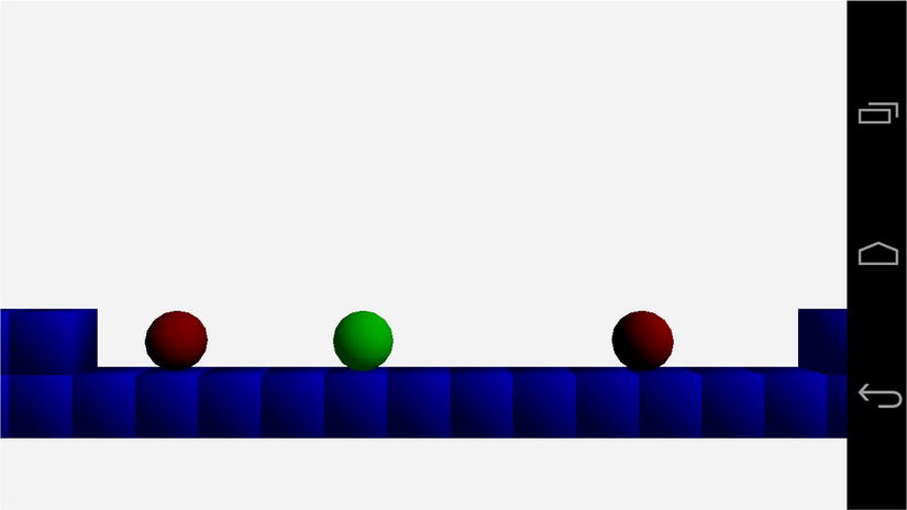
Figure 9-3. Diffuse lighting
As is evident from the preceding screenshot, we have set up our diffuse light source to be situated above and to the right of our objects. The light shines most brightly in those areas and becomes darker on the bottom left of the objects. We can also see the spherical shape of the player and AI objects, as well as the depth of our cubes.
The remaining component of the Blinn-Phong lighting model is the specular component. We look at this next.
The specular component of the lighting equation is responsible for the apparent shininess of a given object. So far, the ambient component has given a base level of light to show color in the darkest areas of our objects. The diffuse component has added the majority of lighting to the object, which helps determine the color and shape of the object in our scene. The specular component is now added to these to make an object appear more or less reflective. Just as with the diffuse component, the specular component has an equation which we will implement in our fragment shader. That equation is as follows:
specular color = max(H.N, 0)^S × specular light color × specular material color
The preceding equation contains the modification to the Phong shading model made by Blinn. The original model contained the vector R instead of H. R represented a reflected light vector which had to be calculated for every vertex in a given model. The vector H represents a half vector and can be calculated once for each model:
half vector = normalize(eye vector + light vector)
The preceding equation relies on the eye vector and the light vector being normal vectors pointing to the camera position and the light source, respectively.
The specular exponent, S from the specular equation, controls the shininess of a material. The higher this exponent, the less shiny the surface.
We’ll now take a look at the vertex shader for this component of the lighting equation.
Specular Component Vertex Shader
The vertex shader for the specular component of the Blinn-Phong model is shown in Listing 9-14.
Listing 9-14. TransformAmbientDiffuseSpecularShader's Vertex Shader. TransformAmbientDiffuseSpecularShader.cpp
m_vertexShaderCode =
       "uniform mat4 u_mModelViewProj;
"
       "uniform mat3 u_mModelIT;
"
       "attribute vec4 a_vPosition;
"
       "attribute vec3 a_vNormal;
"
       "varying   vec3 v_vNormal;
"
       "void main(){
"
       "    gl_Position = u_mModelViewProj * a_vPosition;
"
       "    v_vNormal = normalize(u_mModelIT * a_vNormal);
"
       "}
";
Hopefully, it comes as no surprise that our vertex shader does not differ from the vertex shader used in TransformAmbientDiffuseShader. We are using Phong shading to calculate our lighting values at a per-pixel level. We’ll move straight on to the fragment shader.
Specular Component Fragment Shader
Our fragment shader will add the next additive component of the Blinn-Phong model, the specular component. We have already looked at the equation for this component, so Listing 9-15 gets straight into the fragment shader source code.
Listing 9-15. TransformAmbientDiffuseSpecularShader's Fragment Shader. TransformAmbientDiffuseSpecularShader.cpp
m_fragmentShaderCode =
       "precision mediump float;
"
       "varying   vec3 v_vNormal;
"
       "
"
       "uniform vec4 u_vAmbientColor;
"
       "uniform vec4 u_vDiffuseColor;
"
       "uniform vec4 u_vSpecularColor;
"
       "uniform float u_fSpecularExponent;
"
       "uniform vec4 u_vAmbientLight;
"
       "uniform vec4 u_vDiffuseLight;
"
       "uniform vec4 u_vSpecularLight;
"
       "uniform vec3 u_vLightDirection;
"
       "uniform vec3 u_vLightHalfVector;
"
       "
"
       "const float c_zero = 0.0;
"
       "const float c_one  = 1.0;
"
       "
"
       "void main(){
"
       "    gl_FragColor = vec4(c_zero, c_zero, c_zero, c_zero);
"
       "
"
       "    float ndoth =  dot(u_vLightHalfVector, v_vNormal);
"
       "    ndoth = max(ndoth, c_zero);
"
       "    float dotPow = pow(ndoth, u_fSpecularExponent);
"
       "    gl_FragColor += dotPow * u_vSpecularColor * u_vSpecularLight;
"
       "
"
       "    float ndotl = dot(u_vLightDirection, v_vNormal);
"
       "    ndotl = max(ndotl, c_zero);
"
       "    gl_FragColor += ndotl * u_vDiffuseLight * u_vDiffuseColor;
"
       "
"
       "    gl_FragColor += u_vAmbientLight * u_vAmbientColor;
"
       "
"
       "    gl_FragColor.a = c_one;
"
       "}
";
As our new shader contains both the ambient and diffuse components, it retains all of the uniforms necessary for those calculations. Our newly introduced uniforms are u_vSpecularColor, u_fSpecularExponent, u_vSpecularLight, and u_vLightHalfVector.
There are four new lines in the shader which calculate the specular component. The first calculates the dot product between u_vLightHalfVector and v_vNormal. This gives us the angle between the half vector and the fragment’s normal vector. We then take the higher of either the dot product or zero. The result of the previous steps is then raised to the power of the specular component, and finally the dot product raised to the specular exponent is multiplied by the specular material and light colors.
As the equation is an additive process, we add the diffuse component and then the ambient component to get to the final fragment color.
With our shader code complete, the last step is to look at the OpenGL ES 2.0 code we require to put the shader into use.
Initializing TransformAmbientDiffuseSpecularShader
Like all of our shaders, we must override the Link and Setup methods to be able to use this specific shader.
We look at TransformAmbientDiffuseSpecularShader::Link in Listing 9-16.
Listing 9-16. TransformAmbientDiffuseSpecularShader::Link. TransformAmbientDiffuseSpecularShader.cpp
void TransformAmbientDiffuseSpecularShader::Link()
{
       Shader::Link();
       m_modelViewProjUniformHandle     = glGetUniformLocation(m_programId, "u_mModelViewProj");
       m_modelITMatrixUniformHandle     = glGetUniformLocation(m_programId, "u_mModelIT");
       m_positionAttributeHandle        = glGetAttribLocation(m_programId,  "a_vPosition");
       m_normalAttributeHandle          = glGetAttribLocation(m_programId,  "a_vNormal");
       m_ambientColorUniformHandle      = glGetUniformLocation(m_programId, "u_vAmbientColor");
       m_diffuseColorUniformHandle      = glGetUniformLocation(m_programId, "u_vDiffuseColor");
       m_specularColorUniformHandle     = glGetUniformLocation(m_programId, "u_vSpecularColor");
       m_specularExponentUniformHandle  = glGetUniformLocation(m_programId, "u_fSpecularExponent");
       m_ambientLightUniformHandle      = glGetUniformLocation(m_programId, "u_vAmbientLight");
       m_diffuseLightUniformHandle      = glGetUniformLocation(m_programId, "u_vDiffuseLight");
       m_specularLightUniformHandle     = glGetUniformLocation(m_programId, "u_vSpecularLight");
       m_lightDirectionUniformHandle    = glGetUniformLocation(m_programId, "u_vLightDirection");
       m_lightHalfVectorUniformHandle   = glGetUniformLocation(m_programId, "u_vLightHalfVector");
}
In Link, we obtain all of the handles required for setting the uniforms and attributes using the OpenGL ES 2.0 methods glGetUniformLocation and glGetAttribLocation. We put these handles to use in TransformAmbientDiffuseSpecularShader::Setup, shown in Listing 9-17.
Listing 9-17. Listing 9-17. TransformAmbientDiffuseSpecularShader::Setup. TransformAmbientDiffuseSpecularShader.cpp
void TransformAmbientDiffuseSpecularShader::Setup(Renderable& renderable)
{
       Geometry* pGeometry = renderable.GetGeometry();
       if (pGeometry)
       {
              Shader::Setup(renderable);
              Renderer& renderer = Renderer::GetSingleton();
              const Matrix4& viewMatrix = renderer.GetViewMatrix();
              const Matrix4& projectionMatrix = renderer.GetProjectionMatrix();
              const Matrix4& modelMatrix = renderable.GetTransform().GetMatrix();
              Matrix4 modelViewMatrix;
              modelMatrix.Multiply(viewMatrix, modelViewMatrix);
              Matrix4 modelViewProjectionMatrix;
              modelViewMatrix.Multiply(projectionMatrix, modelViewProjectionMatrix);
              glUniformMatrix4fv(
                     m_modelViewProjUniformHandle,
                     1,
                     false,
                     modelViewProjectionMatrix.m_m);

              Matrix3 modelIT;
              renderable.GetTransform().GetInverseTransposeMatrix(modelIT);
              glUniformMatrix3fv(m_modelITMatrixUniformHandle, 1, false, modelIT.m_m);
              glVertexAttribPointer(
                     m_positionAttributeHandle,
                     pGeometry->GetNumVertexPositionElements(),
                     GL_FLOAT,
                     GL_FALSE,
                     pGeometry->GetVertexStride(),
                     pGeometry->GetVertexBuffer());
              glEnableVertexAttribArray(m_positionAttributeHandle);
              glVertexAttribPointer(
                     m_normalAttributeHandle,
                     pGeometry->GetNumNormalPositionElements(),
                     GL_FLOAT,
                     GL_FALSE,
                     pGeometry->GetVertexStride(),
                     static_cast<float*>(pGeometry->GetVertexBuffer()) +
                            pGeometry->GetNumVertexPositionElements());
              glEnableVertexAttribArray(m_normalAttributeHandle);
              const Vector4& ambientColor = renderable.GetMaterial()->GetAmbientColor();
              glUniform4f(
                     m_ambientColorUniformHandle,
                     ambientColor.m_x,
                     ambientColor.m_y,
                     ambientColor.m_z,
                     ambientColor.m_w);

              const Vector4& diffuseColor = renderable.GetMaterial()->GetDiffuseColor();
              glUniform4f(
                     m_diffuseColorUniformHandle,
                     diffuseColor.m_x,
                     diffuseColor.m_y,
                     diffuseColor.m_z,
                     diffuseColor.m_w);

 const Vector4&specularColor = renderable.GetMaterial()->GetSpecularColor();
 glUniform4f(
 m_specularColorUniformHandle,
 specularColor.m_x,
 specularColor.m_y,
 specularColor.m_z,
 specularColor.m_w);

 glUniform1f(
 m_specularExponentUniformHandle,
 renderable.GetMaterial()->GetSpecularExponent());
              const Vector4& ambientLightColor = renderer.GetAmbientLightColor();
              glUniform4f(
                     m_ambientLightUniformHandle,
                     ambientLightColor.m_x,
                     ambientLightColor.m_y,
                     ambientLightColor.m_z,
                     ambientLightColor.m_w);

              const Vector4& diffuseLightColor = renderer.GetDiffuseLightColor();
              glUniform4f(
                     m_diffuseLightUniformHandle,
                     diffuseLightColor.m_x,
                     diffuseLightColor.m_y,
                     diffuseLightColor.m_z,
                     diffuseLightColor.m_w);

 const Vector4&
specularLightColor = renderer.GetSpecularLightColor();
 glUniform4f(
 m_specularLightUniformHandle,
 specularLightColor.m_x,
 specularLightColor.m_y,
 specularLightColor.m_z,
 specularLightColor.m_w);

              const Vector3& lightDirection = renderer.GetLightDirection();
              glUniform3f(
                     m_lightDirectionUniformHandle,
                     lightDirection.m_x,
                     lightDirection.m_y,
                     lightDirection.m_z);

 Vector3 lightHalfVector = renderer.GetCameraTransform().GetTranslation();
 lightHalfVector.Subtract(
 Vector3(modelMatrix.m_m[12], modelMatrix.m_m[13], modelMatrix.m_m[14]));
 lightHalfVector.Normalize();
 lightHalfVector.Add(lightDirection);
 lightHalfVector.Normalize();
 glUniform3f(
 m_lightHalfVectorUniformHandle,
 lightHalfVector.m_x,
 lightHalfVector.m_y,
 lightHalfVector.m_z);
       }
}
The lines of code which are in bold in the preceding listing are the lines which differ between TransformAmbientDiffuseSpecularShader::Setup and TransformAmbientDiffuseShader::Setup.
The first block is responsible for uploading the specular color and exponent of the object’s material to the GPU. The second identified section uploads the light’s specular color to the GPU.
The last section is responsible for calculating the light’s half vector. We begin by getting the position of the camera object in world space. By subtracting the model’s position, we obtain a vector which points in the direction of the camera from the model. We then turn this into a unit normal by calling the Normalize method. Now we find the vector halfway between the eye vector and the light vector by adding them together. Once we have this vector, we would like to be a unit normal once again, so we call Normalize for a second time. Calculating this vector once for each model is the optimization which Blinn made to the original Phong lighting model.
With the specular component now added to the shader, we can see the results of the complete lighting equation. Figure 9-4 shows a screenshot containing the final result.

Figure 9-4. The complete Blinn-Phong lighting model
Figure 9-5 shows each of the figures from this chapter together.
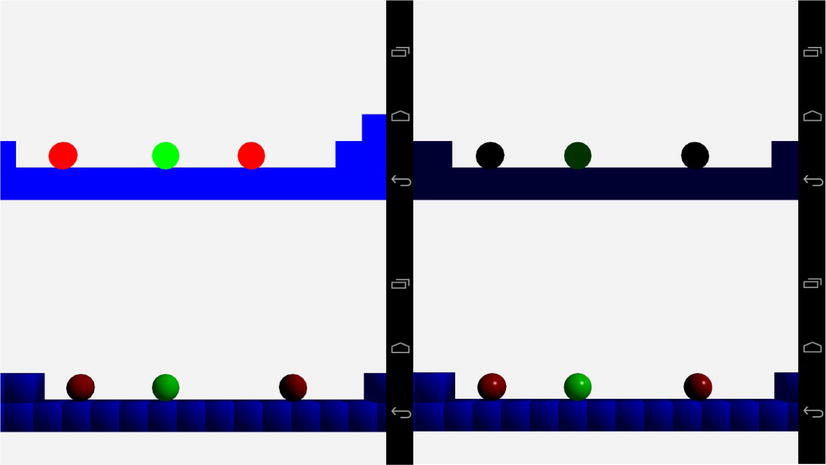
Figure 9-5. A composite of the screenshots seen in Chapter 9
Starting in the top left corner, we have the unlit scene. The colors are fully saturated and the objects in the scene all look completely flat.
Moving to the top right tile, we see the ambient lit scene. While the first tile shows the scene unlit, in reality it’s fully lit with ambient color. An unlit scene would actually appear completely black. Our ambient scene adds a base layer of light and we can slightly see the green shade of the player object.
The bottom left image shows the scene with some definition to the objects for the first time. This is thanks to the diffuse lighting, which is the first lighting component that takes into account whether a given fragment is pointing toward the light source or away.
The last image shows our scene with the specular component of the lighting equation added. This adds a hint of reflectivity to our objects’ surfaces. Where the diffuse lit objects look like solid objects, they are slightly uninteresting. The specular highlight on the final image manages to make our spheres take a more realistic appearance.
This simple model is more than enough to add lighting to our game. The following sections of this chapter will describe some different options for adding lighting and materials to a game via shaders.
Different Types of Lights
The type of light which we have developed in this chapter is called a directional light. This is a computationally simple light model, which benefits our mobile-based game. Mobile GPUs are currently not as powerful as those available in game consoles or desktop PCs. Undoubtedly, the next few years will see a vast increase in the processing power of GPUs in mobile phones and tablets, but for now, games targeting these devices cannot use overly complicated lighting models in their shaders.
This section will discuss two other types of lights which might find greater use as mobile GPUs become more powerful.
In forward shading, a single pass is used where all computations to create the final image are carried out. The directional lights which we have implemented in this chapter are examples of lights which fall into the forward shading category.
The major drawback from this approach is that it requires a large amount of computation to calculate the lighting components from multiple light sources for every rendered object. This cost of computation per light source constrains the number of active lights in any given scene, and many games resort to precalculating their lighting and including it in the textures to be applied to the game levels themselves, either by changing the textures used in the levels or by implementing light maps. The benefit, especially on modern mobile graphics hardware, is that a single target rendering surface is used, and therefore there is not a cost associated with switching render targets when running multiple rendering passes.
Other types of lights which are useful in forward shading are point lights and spotlights.
A point light is different from the directional light which we have described in our shaders, in that it has a position in the world. This means that the light can be placed inside the world and light objects from different directions.
A point light affects all objects by calculating the light direction at each vertex by subtracting the vertex’s position from the light position. Doing this creates a spherical shape for the light source.
Point lights are usually also implemented with an attenuation algorithm. The attenuation of a light causes it to have less of an effect on an object the further away from the light that object becomes. Directional lights are used to simulate lights which are infinitely far away, such as a simple sunlight model, so the attenuation factor makes little sense for them.
The addition of the calculation of the light vector and the attenuation factor increases the computational complexity of the vertex shader. If your game is very simple, this type of light may be feasible, but in most games multiple lights of this type are needed to create the desired effects. This usually puts this technique out of the reach of most low-end mobile GPUs for scenes which have some geometric complexity.
Spotlights are another type of light which are even more complex than point lights. Spotlights have a position and a direction. When spotlights are implemented, they resemble the effects of a torch. Spotlights contain an attenuation factor like point lights but they also have a spotlight cutoff parameter.
This cutoff parameter defines the half angle of the cone of the spotlight. This determines how wide the spotlight is. Anything outside of the cone created by the direction and angle will not be lit by the spotlight. Spotlights also have another attenuation factor which determines the brightness of the light from the center of the cone out to the sides. This allows the spotlight to be brighter in the middle and gradually fade toward the edges of the cone.
Point lights and spotlights were the types of lights which were supplied by OpenGL ES 1.0, and their implementation in the traditional manner is known as forward shading. A modern technique for compositing a scene in modern games is known as deferred rendering.
An alternative technique which has been put to use in many games on the Xbox 360 and Playstation 3 is deferred rendering.
Deferred rendering is usually implemented in two passes. The first pass renders into several buffers. The diffuse color of objects is stored in the diffuse color G buffer. This is different from the diffuse color as we implemented it in the Blinn-Phong model. The stored color is simply the single diffuse material color of the object. No ambient light is used in deferred rendering, and any specular lighting is calculated later. Along with the diffuse G buffer, a normal G buffer stores the normal vectors for each fragment, and the z buffer stores the depth of each fragment at each location.
The second pass then renders a geometric shape for each light. The lighting equation is calculated at each location using the light’s information along with the color, normal, and depth read from the buffers written in the first pass.
The benefit of this model is that hundreds of lights can be rendered in a scene, as they are calculated only for pixels in the frame which will actually make it into the final image. The downside is that it can’t handle transparent objects, so you still need a traditional rendering pass for these.
Another advanced topic which can be implemented with shaders is different types of materials. This is done using different lighting equations in the shaders. These equations are known as bidirectional reflectance distribution functions (BRDFs).
Bidirectional Reflectance Distribution Functions
BRDFs are a group of equations which describe methods for calculating reflected vectors. The Blinn-Phong equation which we have implemented in this chapter is just one example of this set of equations.
The Blinn-Phong model is very good for approximating materials which have a look similar to plastic. Fixed-function graphics pipelines such as those found in OpenGL ES 1.0 have exposed only this model to game developers, but with OpenGL ES 2.0 programmers are free to implement more types of BRDFs thanks to shaders.
Entire books have been written on the subject of lighting in computer graphics, and if you are interested in learning more about BRDFs, the major models to begin with are the Torrance-Sparrow model, the Oren-Nayer diffuse reflection model, and Ward’s reflection model.
These different lighting equations are better suited to recreating the look of different materials such as metals, paper, velvet, sand, and wood.
Summary
In this chapter, we have finally added a sense of depth to our scene. We have achieved this by adding new shader programs which implement a directional light.
We’ve learned that directional lights are used in games to create a simple model of light sources which are very far from our game objects. A real-world example of a directional light source is the sun. We all know that the sun does not emit parallel rays of light, and this shows how we can use simplifications to simulate simple models of real-world phenomenon. This ability to simplify the physical world is a key skill for a game programmer who is working on real-time games which rely on completing the computations for an entire frame in 33 milliseconds or less.
The Blinn-Phong shading model was covered and implemented in GLSL shaders. The sample code provided at http://www.apress.com/9781430258308 to accompany this chapter contains implementations of all of the shader stages described in this chapter. You can switch between them to see how each lighting component behaves, and you can alter the material and light colors as well as the specular exponent to get a feeling for how this lighting model behaves with different parameters.
You should now also be aware that the Blinn-Phong model consists of three different components which make up the final color in a fragment shader. The ambient color is a base level of light applied to an object. The diffuse color determines the main aspect of the objects color and takes into account the intensity of the reflected light based on the angle between the vertex normal and the light vector. The last component is the specular component. This component adds an element of reflectivity to the surface and is also the component of the Phong model which was adapted by Blinn to create the Blinn-Phong model.
We finished the section by covering some details of further topics in the area of lighting and materials. While this is a beginner-level text, it’s important to know that the lighting and material properties of a game engine constitute a deep and very interesting topic. Vertex and fragment shaders have opened up the possibilities of photo-realistic material rendering to game developers, and shader programming will be an ever-evolving and interesting topic as GPUs become capable of implementing ever-more-complex lighting models.
In the next chapter, we are going to move on from the player’s sense of sight and engage their sense of sound. Audio is an exceptionally important aspect of modern video games, and while audio used to be an overlooked part of the development process, this is no longer the case. Successful titles plan their audio early in production, and audio designers and engineers are hired for these specialized roles.