
3D programming is an incredibly wide and complex field. This chapter explores some topics that are the absolute minimum requirement in order to write a simple 3D game:
We’ll revisit our friend the vector and attach one more coordinate.
Lighting is a vital part of any 3D game. We’ll look at how to perform simple lighting with OpenGL ES.
Defining objects programmatically is cumbersome. We’ll look at a simple 3D file format so that we can load and render 3D models created with 3D modeling software.
In Chapter 8, we discussed object representation and collision detection. We’ll look at how to do the same in 3D.
We’ll also briefly revisit some of the physics concepts that we explored in Chapter 8—this time in a 3D context.
Let’s start with 3D vectors.
Before We Begin
As always, we’ll create a couple of simple example programs in this chapter. To do that, we just create a new project and copy over all of the source code of the framework we’ve developed so far.
As in previous chapters, we’ll have a single test starter activity that presents us with the tests in the form of a list. We’ll call it GLAdvancedStarter and make it our default activity. Simply copy over the GL3DBasicsStarter and replace the class names of the tests. We also need to add each of the test activities to the manifest with a proper <activity> element.
Each of the tests will extend GLGame as usual; the actual code will be implemented as a GLScreen instance that we’ll hook up with the GLGame instance. As in Chapter 10, to conserve space we’ll present only the relevant portions of the GLScreen implementations. All of the tests and the starter activity reside within the package com.badlogic.androidgames.gladvanced. Some of the classes will be part of our framework and will go into the respective framework packages.
Vectors in 3D
In Chapter 8, we discussed vectors and their interpretation in 2D. As you might have guessed, all of the things we discussed there still hold in 3D space. All we need to do is to add one more coordinate to our vector, namely the z coordinate.
The operations we looked at with vectors in 2D can be easily transferred to 3D space. We specify vectors in 3D with a statement like the following:
v = (x,y,z)
Addition in 3D is carried out as follows:
c = a + b = (a.x, a.y, b.z) + (b.x, b.y, b.z) = (a.x + b.x, a.y + b.y, a.z + b.z)
Subtraction works exactly the same way:
c = a – b = (a.x, a.y, b.z) – (b.x, b.y, b.z) = (a.x – b.x, a.y – b.y, a.z – b.z)
Multiplying a vector by a scalar works like this:
a' = a * scalar = (a.x * scalar, a.y * scalar, a.z * scalar)
Measuring the length of a vector in 3D is also quite simple; we just add the z coordinate to the Pythagorean equation:
|a| = sqrt(a.x * a.x + a.y * a.y + a.z * a.z)
Based on this, we can also normalize our vectors to unit length again:
a' = (a.x / |a|, a.y / |a|, a.z / |a|)
All of the interpretations of vectors we talked about in Chapter 8 hold in 3D as well:
Positions are just denoted by a normal vector’s x, y, and z coordinates.
Velocities and accelerations can also be represented as 3D vectors. Each component then represents a certain quantity of the attribute on one axis, such as meters per second (m/s) in the case of velocity or meters per second per second (m/s2) for acceleration.
We can represent directions (or axes) as simple 3D unit vectors. We did that in Chapter 8 when we used the rotation facilities of OpenGL ES.
We can measure distances by subtracting the starting vector from the end vector and measuring the resulting vector’s length.
One more operation that can be rather useful is the rotation of a 3D vector around a 3D axis. We used this principle earlier via the OpenGL ES glRotatef() method. However, we can’t use it to rotate one of the vectors that we’ll use to store the positions or directions of our game objects, because it only works on vertices that we submit to the GPU. Luckily, there’s a Matrix class in the Android API that allows us to emulate what OpenGL ES does on the GPU. Let’s write a Vector3 class that implements all of these features. Listing 11-1 shows the code, which we’ll again explain along the way.
Listing 11-1. Vector3.java, a vector in 3D
package com.badlogic.androidgames.framework.math;import android.opengl.Matrix;import android.util.FloatMath;public class Vector3 {private static final float[] matrix = new float[16];private static final float[] inVec = new float[4];private static final float[] outVec = new float[4];public float x, y, z;
The class starts with a couple of private static final float arrays. We’ll need them later on when we implement the new rotate() method of our Vector3 class. Just remember that the matrix member has 16 elements and the inVec and outVec members each have 4 elements. We create those three arrays so that we don’t have to create them later on, all the time. This will keep the garbage collector happy. Just remember that by doing so, the Vector3 class is not thread safe!
The x, y, and z members defined next should be self-explanatory. They store the actual components of the vector:
public Vector3() {}public Vector3(float x, float y, float z) {this.x = x;this.y = y;this.z = z;}public Vector3(Vector3 other) {this.x = other.x;this.y = other.y;this.z = other.z;}public Vector3 cpy() {return new Vector3(x, y, z);}public Vector3 set(float x, float y, float z) {this.x = x;this.y = y;this.z = z;return this;}public Vector3 set(Vector3 other) {this.x = other.x;this.y = other.y;this.z = other.z;return this;}
Like Vector2, our Vector3 class has a couple of constructors and setters, as well as a cpy() method so that we can easily clone vectors or set them from components calculated in our program.
public Vector3 add(float x, float y, float z) {this.x += x;this.y += y;this.z += z;return this;}public Vector3 add(Vector3 other) {this.x += other.x;this.y += other.y;this.z += other.z;return this;}public Vector3 sub(float x, float y, float z) {this.x -= x;this.y -= y;this.z -= z;return this;}public Vector3 sub(Vector3 other) {this.x -= other.x;this.y -= other.y;this.z -= other.z;return this;}public Vector3 mul(float scalar) {this.x *= scalar;this.y *= scalar;this.z *= scalar;return this;}
The various add(), sub(), and mul() methods are just an extension of what we had in our Vector2 class with an additional z coordinate. They implement what we discussed a few pages ago. Straightforward, right?
public float len() {return (float)Math.sqrt(x * x + y * y + z * z);}public Vector3 nor() {float len = len();if (len != 0) {this.x /= len;this.y /= len;this.z /= len;}return this;}
The len() and nor() methods are also essentially the same as in the Vector2 class. All we do is incorporate the new z coordinate into the calculations.
public Vector3 rotate(float angle, float axisX, float axisY, float axisZ) {inVec[0] = x;inVec[1] = y;inVec[2] = z;inVec[3] = 1;Matrix.setIdentityM(matrix, 0);Matrix.rotateM(matrix, 0, angle, axisX, axisY, axisZ);Matrix.multiplyMV(outVec, 0, matrix, 0, inVec, 0);x = outVec[0];y = outVec[1];z = outVec[2];return this;}
And here’s our new rotate() method. As indicated earlier, it makes use of Android’s Matrix class. The Matrix class essentially consists of a couple of static methods, like Matrix.setIdentityM() and Matrix.rotateM(). These operate on float arrays, similar to the ones we defined earlier. A matrix is stored as 16 float values, and a vector is expected to have four elements. We won’t go into detail about the inner workings of the class; all we need is a way to emulate the matrix capabilities of OpenGL ES on the Java side, and that’s exactly what this class offers to us. All of the methods work on a matrix and operate in exactly the same way as glRotatef(), glTranslatef(), and glIdentityf() in OpenGL ES.
The rotate() method starts off by setting the vector’s components to the inVec array we defined earlier. Next, we call Matrix.setIdentityM() on the matrix member of our class. This will “clear” the matrix. With OpenGL ES, we used glIdentityf() to do the same thing with matrices residing on the GPU. Next, we call Matrix.rotateM(). It takes as parameters the float array holding the matrix, an offset into that array, the angle we want to rotate by in degrees, and the (unit length) axis we want to rotate around. This method is equivalent to glRotatef(). It will multiply the given matrix by a rotation matrix. Finally, we call Matrix.multiplyMV(), which will multiply our vector stored in inVec by the matrix. This applies all of the transformations stored in the matrix to the vector. The result will be output in outVec. The rest of the method just grabs the resulting new components from the outVec array and stores them in the Vector3 class’s members.
Note
You can use the Matrix class to do a lot more than just rotate vectors. It operates in exactly the same way as OpenGL ES in its effects on the passed-in matrix.
public float dist(Vector3 other) {float distX = this.x - other.x;float distY = this.y - other.y;float distZ = this.z - other.z;return (float)Math.sqrt(distX * distX + distY * distY + distZ * distZ);}public float dist(float x, float y, float z) {float distX = this.x - x;float distY = this.y - y;float distZ = this.z - z;return (float)Math.sqrt(distX * distX + distY * distY + distZ * distZ);}public float distSquared(Vector3 other) {float distX = this.x - other.x;float distY = this.y - other.y;float distZ = this.z - other.z;return distX * distX + distY * distY + distZ * distZ;}public float distSquared(float x, float y, float z) {float distX = this.x - x;float distY = this.y - y;float distZ = this.z - z;return distX * distX + distY * distY + distZ * distZ;}}
Finally, we have the usual dist() and distSquared() methods to calculate the distance between two vectors in 3D.
Note that we left out the angle() method we saw in Vector2. While it is possible to measure the angle between two vectors in 3D, that does not give us an angle in the range 0 to 360. Usually, we get away with just evaluating the angle between two vectors in the x/y, z/y, and x/z planes by using only two components of each vector and applying the Vector2.angle() method. We won’t need this functionality until our last game, so we’ll return to the topic at that point.
An explicit example of using this class isn’t necessary. We can just invoke it the same way we did with the Vector2 class in Chapter 8. On to the next topic: lighting in OpenGL ES.
Lighting in OpenGL ES
Lighting in OpenGL ES is a useful feature that can give our 3D games a nice touch. To use this functionality, we have to have an idea of the OpenGL ES lighting model.
How Lighting Works
Let’s think about how lighting works for a moment. The first thing we need is a light source to emit light. We also need an object that can be lit. Finally, we need a sensor, like our eyes or a camera, that will catch the photons that are sent out by the light source and are reflected back by the object. Lighting changes the perceived color of an object depending on the following:
The light source’s type
The light source’s color and intensity
The light source’s position and direction relative to the lit object
The object’s material and texture
The intensity with which light is reflected by an object can depend on various factors. We are mostly concerned with the angle at which a light ray hits a surface. The more perpendicular a light ray is to a surface it hits, the greater the intensity of the light reflected by the surface. Figure 11-1 illustrates this point.
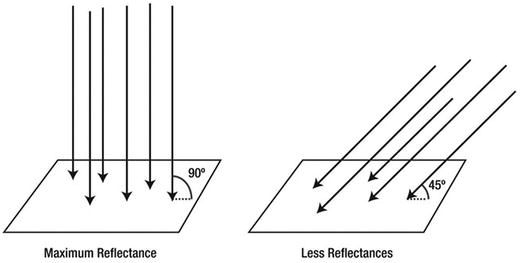
Figure 11-1. The more perpendicular a light ray is to a surface, the greater the intensity of the reflected light.
Once a light ray hits a surface, it is reflected in two different ways. Most of the light is reflected diffusely, which means that the reflected light rays are scattered randomly by irregularities of the object’s surface. Some reflections are specular, which means that the light rays bounce back as if they had hit a perfect mirror. Figure 11-2 shows the difference between diffuse and specular reflection.

Figure 11-2. Diffuse and specular reflection
Specular reflection will manifest itself as highlights on objects. Whether an object will cast specular reflections depends on its material. Objects with rough or uneven surfaces, like skin or fabric, are unlikely to have specular highlights. Objects that have a smooth surface, like glass or a marble, do exhibit these lighting artifacts. Of course, glass or marble surfaces aren’t really smooth in an absolute sense, either. Relative to materials like wood or human skin, though, they are very smooth.
When light hits a surface, its reflection also changes color depending on the chemical constitution of the object it hits. The objects we see as red, for example, are those that reflect only the red portions of light. The object “swallows” all other wavelengths. A black object is one that swallows almost all of the light that is shone on it.
OpenGL ES allows us to simulate this real-world behavior by specifying light sources and materials of objects.
Light Sources
We are surrounded by all kinds of light sources. The sun constantly throws photons at us. Our monitors emit light, surrounding us with that nice blue glow at night. Light bulbs and headlights keep us from bumping or driving into things in the dark. OpenGL ES enables us to create four types of light sources:
Ambient light: Ambient light is not a light source per se but rather is the result of photons coming from other light sources and bouncing around in our world. The combination of all of these stray photons makes for a certain default level of illumination that is directionless and illuminates all objects equally.
Point lights: These have a position in space and emit light in all directions. A light bulb is a point light, for example.
Directional lights: These are expressed as directions in OpenGL ES and are assumed to be infinitely far away. The sun can be idealized as a directional light source. We can assume that the light rays coming from the sun all hit the Earth at the same angle because of the distance between the earth and the sun.
Spotlights: These are similar to point lights in that they have an explicit position in space. Additionally, they have a direction in which they shine and create a light cone that is limited to some radius. A street lamp is a spotlight.
We’ll only look into ambient, point, and directional lights. Spotlights are often hard to get right with limited GPUs like those found on Android devices because of the way OpenGL ES calculates the lighting. You’ll see why that is in a minute.
Besides a light source’s position and direction, OpenGL ES lets us also specify the color or intensity of a light. This is expressed as an RGBA color. However, OpenGL ES requires us to specify four different colors per light source instead of just one:
Ambient: This is the intensity/color that contributes to the overall shading of an object. An object will be uniformly lit with this color, no matter its position or orientation relative to the light source.
Diffuse: This is the intensity/color with which an object will be lit when calculating the diffuse reflection. Sides of an object that do not face the light source won’t be lit, just as in real life.
Specular: This intensity/color is similar to the diffuse color. However, it will only affect spots on the object that have a certain orientation toward the viewer and the light source.
Emissive: This is totally confusing and has very little use in real-world applications, so we won’t go into it.
Usually, we’ll only set the diffuse and specular intensities of a light source and leave the other two at their defaults. We’ll also use the same RGBA color for both the diffuse and specular intensities most of the time.
Materials
Every object in our world has a material covering. The material not only defines how the light that is hitting the object will be reflected but also modifies the color of the reflected light. OpenGL ES lets us specify the same four RGBA colors for a material as we can for a light source:
Ambient: This is the color that’s combined with the ambient color of any light source in the scene.
Diffuse: This is the color that’s combined with the diffuse color of any light source.
Specular: This is the color that’s combined with the specular color of any light source for specular highlight points on an object’s surface.
Emissive: We again ignore this as it has little use in our context.
Figure 11-3 illustrates the first three types of material/light source properties: ambient, diffuse, and specular.

Figure 11-3. Different material/light types. Left: ambient only. Center: Diffuse only. Right: Ambient and diffuse with specular highlight
In Figure 11-3, we can see the contributions of the different material and light properties. Ambient light illuminates the object uniformly. Diffuse light will be reflected depending on the angle at which the light rays hit the object; areas that directly face the light source will be brighter, and areas that can’t be reached by light rays are dark. The rightmost image shows the combination of ambient, diffuse, and specular light. The specular light manifests itself as a white highlight on the sphere.
How OpenGL ES Calculates Lighting: Vertex Normals
You know that the intensity of the reflected light bouncing back from an object depends on the angle at which the light rays hit the surface of the object. OpenGL ES uses this fact to calculate lighting. It does so by using vertex normals, which we have to define in our code, just as we define texture coordinates and vertex colors. Figure 11-4 shows a sphere with its vertex normals.

Figure 11-4. A sphere and its vertex normals
Normals are simply unit-length vectors that point in the direction a surface is facing. In our case, a surface is a triangle. Instead of specifying a surface normal, though, we have to specify a vertex normal. The difference between a surface normal and a vertex normal is that the vertex normal might not have to point in the same direction as the surface normal. We can clearly see this in Figure 11-4, where each vertex normal is actually the average of the normals of the triangles to which that vertex belongs. This averaging makes for a smooth shading of the object.
When we render an object with vertex normals and lighting enabled, OpenGL ES will determine the angle between each vertex and light source. With this angle, it can calculate the vertex’s color based on the ambient, diffuse, and specular properties of the material of the object and the light source. The end result is a color for each vertex of an object that is then interpolated over each triangle in combination with the calculated colors of the other vertices. This interpolated color will then be combined with any texture maps we apply to the object.
This sounds scary, but it really isn’t that bad. All we need to do is enable lighting and specify the light sources, the material for the object we want to render, and the vertex normals, in addition to the other vertex attributes we usually specify, like position and texture coordinates. Let’s have a look at how to implement all of this with OpenGL ES.
In Practice
We’ll now go through all of the necessary steps to get lighting to work with OpenGL ES. Along the way, we’ll create a few little helper classes that make working with light sources a bit easier. We’ll put those in the com.badlogic.androidgames.framework.gl package.
Enabling and Disabling Lighting
As with all OpenGL ES states, we first have to enable the functionality in question. We do that with this:
gl.glEnable(GL10.GL_LIGHTING);Once enabled, lighting will be applied to all the objects that we render. Of course, we’ll have to specify the light sources, materials, and vertex normals to achieve meaningful results. After we render all the objects that should be illuminated, we can disable lighting again:
gl.glDisable(GL10.GL_LIGHTING);Specifying Light Sources
As previously discussed, OpenGL ES offers us four types of light sources: ambient lights, point lights, directional lights, and spotlights. We’ll take a look at how to define the first three. In order for spotlights to be effective and to look good, we’d need to have a very high triangle count for each of our objects’ models. This is prohibitive on most current mobile devices.
OpenGL ES limits us to having a maximum of eight light sources in a scene, plus a global ambient light. Each of the eight light sources has an identifier, from GL10.GL_LIGHT0 up to GL10.GL_LIGHT7. If we want to manipulate the properties of one of these light sources, we do so by specifying the respective ID of that light source.
Light sources have to be enabled with this syntax:
gl.glEnable(GL10.GL_LIGHT0);In this case, OpenGL ES will then take the properties of the light source with ID 0 and apply it to all rendered objects accordingly. If we want to disable a light source, we can do it with a statement like this:
gl.glDisable(GL10.GL_LIGHT0);Ambient light is a special case, as it does not have an identifier. There is only one ambient light ever in an OpenGL ES scene. Let’s have a look at that.
Ambient Light
Ambient light is a special type of light, as explained already. It has no position or direction, only a color by which all objects in the scene will be uniformly lit. OpenGL ES lets us specify the global ambient light as follows:
float[] ambientColor = { 0.2f, 0.2f, 0.2f, 1.0f };gl.glLightModelfv(GL10.GL_LIGHT_MODEL_AMBIENT, color, 0);
The ambientColor array holds the RGBA values of the ambient light’s color encoded as floats in the range 0 to 1. The glLightModelfv() method takes as parameters a constant specifying that we want to set the ambient light’s color; the float array holding the color; and an offset into the float array from which the method should start reading the RGBA values. Let’s put this into a lovely little class. Listing 11-2 shows the code.
Listing 11-2. AmbientLight.java, a simple abstraction of OpenGL ES global ambient light
package com.badlogic.androidgames.framework.gl;import javax.microedition.khronos.opengles.GL10;public class AmbientLight {float[] color = {0.2f, 0.2f, 0.2f, 1};public void setColor(float r, float g, float b, float a) {color[0] = r;color[1] = g;color[2] = b;color[3] = a;}public void enable(GL10 gl) {gl.glLightModelfv(GL10.GL_LIGHT_MODEL_AMBIENT, color, 0);}}
All we do is store the ambient light’s color in a float array and then provide two methods: one to set the color and the other to make OpenGL ES use the ambient light color that we define. By default, we use a gray ambient light color.
Point Lights
Point lights have a position as well as an ambient, diffuse, and specular color/intensity (we leave out the emissive color/intensity). To specify the different colors, we can do the following:
gl.glLightfv(GL10.GL_LIGHT3, GL10.GL_AMBIENT, ambientColor, 0);gl.glLightfv(GL10.GL_LIGHT3, GL10.GL_DIFFUSE, diffuseColor, 0);gl.glLightfv(GL10.GL_LIGHT3, GL10.GL_SPECULAR, specularColor, 0);
The first parameter is the light identifier; in this case we use the fourth light. The next parameter specifies the light's attribute that we want to modify. The third parameter is again a float array that holds the RGBA values, and the final parameter is an offset into that array. Specifying the position is easy:
float[] position = {x, y, z, 1};gl.glLightfv(GL10.GL_LIGHT3, GL10.GL_POSITION, position, 0);
We again specify the attribute we want to modify (in this case the position), along with a four-element array that stores the x, y, and z coordinates of the light in our world. Note that the fourth element of the array must be set to 1 for a positional light source! Let’s put this into a helper class. Listing 11-3 shows the code.
Listing 11-3. PointLight.java, a simple abstraction of OpenGL ES point lights
package com.badlogic.androidgames.framework.gl;import javax.microedition.khronos.opengles.GL10;public class PointLight {float[] ambient = { 0.2f, 0.2f, 0.2f, 1.0f };float[] diffuse = { 1.0f, 1.0f, 1.0f, 1.0f };float[] specular = { 0.0f, 0.0f, 0.0f, 1.0f };float[] position = { 0, 0, 0, 1 };int lastLightId = 0;public void setAmbient(float r, float g, float b, float a) {ambient[0] = r;ambient[1] = g;ambient[2] = b;ambient[3] = a;}public void setDiffuse(float r, float g, float b, float a) {diffuse[0] = r;diffuse[1] = g;diffuse[2] = b;diffuse[3] = a;}public void setSpecular(float r, float g, float b, float a) {specular[0] = r;specular[1] = g;specular[2] = b;specular[3] = a;}public void setPosition(float x, float y, float z) {position[0] = x;position[1] = y;position[2] = z;}public void enable(GL10 gl, int lightId) {gl.glEnable(lightId);gl.glLightfv(lightId, GL10.GL_AMBIENT, ambient, 0);gl.glLightfv(lightId, GL10.GL_DIFFUSE, diffuse, 0);gl.glLightfv(lightId, GL10.GL_SPECULAR, specular, 0);gl.glLightfv(lightId, GL10.GL_POSITION, position, 0);lastLightId = lightId;}public void disable(GL10 gl) {gl.glDisable(lastLightId);}}
Our helper class stores the ambient, diffuse, and specular color components of the light as well as the position (with the fourth element set to 1). In addition, we store the last light identifier used for this light so that we can offer a disable() method that will turn off the light if necessary. For each light attribute, we have a nice setter method. We also have an enable()method, which takes a GL10 instance and a light identifier (like GL10.GL_LIGHT6). It enables the light, sets its attributes, and stores the light identifier used. The disable() method just disables the light using the lastLightId member set in enable().
We use sensible defaults for the ambient, diffuse, and specular colors in the initializers of the member arrays. The light will be white, and it will not produce any specular highlights because the specular color is black.
Directional Lights
A directional light is nearly identical to a point light. The only difference is that it has a direction instead of a position. The way the direction is expressed is somewhat confusing. Instead of using a direction vector, OpenGL ES expects us to define a point in the world. The direction is then calculated by taking the direction vector from that point to the origin of the world. The following snippet would produce a directional light that comes from the right side of the world:
float[] dirPos = {1, 0, 0, 0};gl.glLightfv(GL10.GL_LIGHT0, GL10.GL_POSITION, dirPos, 0);
We can translate that to a direction vector:
dir = -dirPos = {-1, 0, 0, 0}The rest of the attributes, like the ambient or diffuse color, are identical to those of a point light. Listing 11-4 shows the code of a little helper class for diffuse lights.
Listing 11-4. DirectionalLight.java, a simple abstraction of OpenGL ES directional lights
package com.badlogic.androidgames.framework.gl;import javax.microedition.khronos.opengles.GL10;public class DirectionalLight {float[] ambient = { 0.2f, 0.2f, 0.2f, 1.0f };float[] diffuse = { 1.0f, 1.0f, 1.0f, 1.0f };float[] specular = { 0.0f, 0.0f, 0.0f, 1.0f };float[] direction = { 0, 0, -1, 0 };int lastLightId = 0;public void setAmbient(float r, float g, float b, float a) {ambient[0] = r;ambient[1] = g;ambient[2] = b;ambient[3] = a;}public void setDiffuse(float r, float g, float b, float a) {diffuse[0] = r;diffuse[1] = g;diffuse[2] = b;diffuse[3] = a;}public void setSpecular(float r, float g, float b, float a) {specular[0] = r;specular[1] = g;specular[2] = b;specular[3] = a;}public void setDirection(float x, float y, float z) {direction[0] = -x;direction[1] = -y;direction[2] = -z;}public void enable(GL10 gl, int lightId) {gl.glEnable(lightId);gl.glLightfv(lightId, GL10.GL_AMBIENT, ambient, 0);gl.glLightfv(lightId, GL10.GL_DIFFUSE, diffuse, 0);gl.glLightfv(lightId, GL10.GL_SPECULAR, specular, 0);gl.glLightfv(lightId, GL10.GL_POSITION, direction, 0);lastLightId = lightId;}public void disable(GL10 gl) {gl.glDisable(lastLightId);}}
Our helper class is nearly identical to the PointLight class. The only difference is that the direction array has its fourth element set to 1. We also have a setDirection() method instead of a setPosition() method. The setDirection() method allows us to specify a direction, like (–1,0,0) so that the light comes from the right side. Inside the method, we just negate all of the vector components so that we transform the direction to the format that OpenGL ES expects from us.
Specifying Materials
A material is defined by a couple of attributes. As with anything in OpenGL ES, a material is a state and will be active until we change it again or the OpenGL ES context is lost. To set the currently active material attributes, we can do the following:
gl.glMaterialfv(GL10.GL_FRONT_AND_BACK, GL10.GL_AMBIENT, ambientColor, 0);gl.glMaterialfv(GL10.GL_FRONT_AND_BACK, GL10.GL_DIFFUSE, diffuseColor, 0);gl.glMaterialfv(GL10.GL_FRONT_AND_BACK, GL10.GL_SPECULAR, specularColor, 0);
As usual, we have an ambient, a diffuse, and a specular RGBA color to specify. We again do this via four-element float arrays, just as we did with the light source attributes. Putting this together into a little helper class is again very easy. Listing 11-5 shows the code.
Listing 11-5. Material.java, a simple abstraction of OpenGL ES materials
package com.badlogic.androidgames.framework.gl;import javax.microedition.khronos.opengles.GL10;public class Material {float[] ambient = { 0.2f, 0.2f, 0.2f, 1.0f };float[] diffuse = { 1.0f, 1.0f, 1.0f, 1.0f };float[] specular = { 0.0f, 0.0f, 0.0f, 1.0f };public void setAmbient(float r, float g, float b, float a) {ambient[0] = r;ambient[1] = g;ambient[2] = b;ambient[3] = a;}public void setDiffuse(float r, float g, float b, float a) {diffuse[0] = r;diffuse[1] = g;diffuse[2] = b;diffuse[3] = a;}public void setSpecular(float r, float g, float b, float a) {specular[0] = r;specular[1] = g;specular[2] = b;specular[3] = a;}public void enable(GL10 gl) {gl.glMaterialfv(GL10.GL_FRONT_AND_BACK, GL10.GL_AMBIENT, ambient, 0);gl.glMaterialfv(GL10.GL_FRONT_AND_BACK, GL10.GL_DIFFUSE, diffuse, 0);gl.glMaterialfv(GL10.GL_FRONT_AND_BACK, GL10.GL_SPECULAR, specular, 0);}}
There are no big surprises here, either. We just store the three components of the material and provide setters and an enable() method, which sets the material.
OpenGL ES has one more trick up its sleeve when it comes to materials. Usually we wouldn’t use glMaterialfv(), but would instead choose something called color material. This means that instead of the ambient and diffuse colors specified via glMaterialfv(), OpenGL ES would take the vertex color of our models as the ambient and diffuse material color. To enable this nice feature, we just have to call it:
gl.glEnable(GL10.GL_COLOR_MATERIAL);We usually use this instead of a full-blown material class, as shown earlier, because ambient and diffuse colors are often the same. Since we also don’t use specular highlights in most of our demos and games, we can get away with just enabling color materials and not using any glMaterialfv() calls at all. The choice of using the Material class or color materials is totally up to you.
Specifying Normals
For lighting to work in OpenGL ES, we have to specify vertex normals for each vertex of a model. A vertex normal must be a unit-length vector that points in the (average) facing direction of the surface(s) to which a vertex belongs. Figure 11-5 illustrates vertex normals for our cube.

Figure 11-5. Vertex normals for each vertex of our cube
A vertex normal is just another vertex attribute, like position or color. In order to upload vertex normals, we have to modify our Vertices3 class one more time. To tell OpenGL ES where it can find the normals for each vertex, we use the glNormalPointer() method, just like we used the glVertexPointer() or glColorPointer() methods previously. Listing 11-6 shows our final revised Vertices3 class.
Listing 11-6. Vertices3.java: The final version, with support for normals
package com.badlogic.androidgames.framework.gl;import java.nio.ByteBuffer;import java.nio.ByteOrder;import java.nio.IntBuffer;import java.nio.ShortBuffer;import javax.microedition.khronos.opengles.GL10;import com.badlogic.androidgames.framework.impl.GLGraphics;public class Vertices3 {final GLGraphics glGraphics;final boolean hasColor;final boolean hasTexCoords;final boolean hasNormals;final int vertexSize;final IntBuffer vertices;final int[] tmpBuffer;final ShortBuffer indices;
Among the members, the only new addition is the hasNormals Boolean, which keeps track of whether the vertices have normals or not.
public Vertices3(GLGraphics glGraphics, int maxVertices, int maxIndices,boolean hasColor, boolean hasTexCoords, boolean hasNormals) {this.glGraphics = glGraphics;this.hasColor = hasColor;this.hasTexCoords = hasTexCoords;this.hasNormals = hasNormals;this.vertexSize = (3 + (hasColor ? 4 : 0) + (hasTexCoords ? 2 : 0) + (hasNormals ? 3 : 0)) * 4;this.tmpBuffer = new int[maxVertices * vertexSize / 4];ByteBuffer buffer = ByteBuffer.allocateDirect(maxVertices * vertexSize);buffer.order(ByteOrder.nativeOrder());vertices = buffer.asIntBuffer();if (maxIndices > 0) {buffer = ByteBuffer.allocateDirect(maxIndices * Short.SIZE / 8);buffer.order(ByteOrder.nativeOrder());indices = buffer.asShortBuffer();} else {indices = null;}}
In the constructor, we now also take a hasNormals parameter. We have to modify the calculation of the vertexSize member as well, adding three floats per vertex if normals are available.
public void setVertices(float[] vertices, int offset, int length) {this.vertices.clear();int len = offset + length;for (int i = offset, j = 0; i < len; i++, j++)tmpBuffer[j] = Float.floatToRawIntBits(vertices[i]);this.vertices.put(tmpBuffer, 0, length);this.vertices.flip();}public void setIndices(short[] indices, int offset, int length) {this.indices.clear();this.indices.put(indices, offset, length);this.indices.flip();}
As you can see, the methods setVertices() and setIndices() stay the same.
public void bind() {GL10 gl = glGraphics.getGL();gl.glEnableClientState(GL10.GL_VERTEX_ARRAY);vertices.position(0);gl.glVertexPointer(3, GL10.GL_FLOAT, vertexSize, vertices);if (hasColor) {gl.glEnableClientState(GL10.GL_COLOR_ARRAY);vertices.position(3);gl.glColorPointer(4, GL10.GL_FLOAT, vertexSize, vertices);}if (hasTexCoords) {gl.glEnableClientState(GL10.GL_TEXTURE_COORD_ARRAY);vertices.position(hasColor ? 7 : 3);gl.glTexCoordPointer(2, GL10.GL_FLOAT, vertexSize, vertices);}if (hasNormals) {gl.glEnableClientState(GL10.GL_NORMAL_ARRAY);int offset = 3;if (hasColor)offset += 4;if (hasTexCoords)offset += 2;vertices.position(offset);gl.glNormalPointer(GL10.GL_FLOAT, vertexSize, vertices);}}
In the bind()method, we do the usual ByteBuffer tricks, this time also incorporating normals via the glNormalPointer() method. To calculate the offset for the normal pointer, we have to take into account whether colors and texture coordinates are given.
public void draw(int primitiveType, int offset, int numVertices) {GL10 gl = glGraphics.getGL();if (indices != null) {indices.position(offset);gl.glDrawElements(primitiveType, numVertices,GL10.GL_UNSIGNED_SHORT, indices);} else {gl.glDrawArrays(primitiveType, offset, numVertices);}}
You can see that the draw() method is again unmodified; all of the magic happens in the bind() method.
public void unbind() {GL10 gl = glGraphics.getGL();if (hasTexCoords)gl.glDisableClientState(GL10.GL_TEXTURE_COORD_ARRAY);if (hasColor)gl.glDisableClientState(GL10.GL_COLOR_ARRAY);if (hasNormals)gl.glDisableClientState(GL10.GL_NORMAL_ARRAY);}}
Finally, we also modify the unbind() method slightly. We disable the normal pointer if normals were used so as to clean up the OpenGL ES state properly.
Using this modified Vertices3 version is as easy as before. Here’s a small example:
float[] vertices = { -0.5f, -0.5f, 0, 0, 0, 1,0.5f, -0.5f, 0, 0, 0, 1,0.0f, 0.5f, 0, 0, 0, 1 };Vertices3 vertices = new Vertices3(glGraphics, 3, 0, false, false, true);vertices.setVertices(vertices);
We create a float array to hold three vertices, each having a position (the first three floats on each line) and a normal (the last three floats on each line). In this case, we have a triangle in the x-y plane with its normals pointing in the direction of the positive z axis. All that’s left to do is create the Vertices3 instance and set the vertices. Easy, right? Binding, drawing, and unbinding work in exactly the same way as with the old version. We can, of course, also add vertex colors and texture coordinates, as we did previously.
Putting It All Together
Let’s put all this lighting knowledge together into an example. We want to draw a scene with a global ambient light, a point light, and a directional light that all illuminate a cube centered at the origin. For good measure, we’ll also throw in a call to gluLookAt() to position our camera in the world. Figure 11-6 shows the setup of our world.

Figure 11-6. Our first lit scene
As with all of our examples, we create a class and call it LightTest, which extends GLGame as usual. It returns a new LightScreen instance from its getStartScreen() method. The LightScreen class extends GLScreen, and this is shown in Listing 11-7.
Listing 11-7. Excerpt from LightTest.java: Lighting with OpenGL ES
class LightScreen extends GLScreen {float angle;Vertices3 cube;Texture texture;AmbientLight ambientLight;PointLight pointLight;DirectionalLight directionalLight;Material material;
We start off with a couple of members. The angle member stores the current rotation of the cube around the y axis. The Vertices3 member stores the vertices of the cube model, which we are going to define in a bit. In addition, we store AmbientLight, PointLight, DirectionalLight, and Material instances.
public LightScreen(Game game) {super(game);cube = createCube();texture = new Texture(glGame, "crate.png“);ambientLight = new AmbientLight();ambientLight.setColor(0, 0.2f, 0, 1);pointLight = new PointLight();pointLight.setDiffuse(1, 0, 0, 1);pointLight.setPosition(3, 3, 0);directionalLight = new DirectionalLight();directionalLight.setDiffuse(0, 0, 1, 1);directionalLight.setDirection(1, 0, 0);material = new Material();}
Next is the constructor. Here we create the cube model’s vertices and load the crate texture, just as we did in Chapter 10. We also instantiate all of the lights and the material and set their attributes. The ambient light color is a light green, and the point light is red and sits at (3,3,0) in our world. The directional light has a blue diffuse color and comes from the left. For the material, we use the default values (a little ambient, white for diffuse, and black for specular).
@Overridepublic void resume() {texture.reload();}
In the resume() method, we make sure that our texture is (re)loaded in case of a context loss.
private Vertices3 createCube() {float[] vertices = { -0.5f, -0.5f, 0.5f, 0, 1, 0, 0, 1,0.5f, -0.5f, 0.5f, 1, 1, 0, 0, 1,0.5f, 0.5f, 0.5f, 1, 0, 0, 0, 1,-0.5f, 0.5f, 0.5f, 0, 0, 0, 0, 1,0.5f, -0.5f, 0.5f, 0, 1, 1, 0, 0,0.5f, -0.5f, -0.5f, 1, 1, 1, 0, 0,0.5f, 0.5f, -0.5f, 1, 0, 1, 0, 0,0.5f, 0.5f, 0.5f, 0, 0, 1, 0, 0,0.5f, -0.5f, -0.5f, 0, 1, 0, 0, -1,-0.5f, -0.5f, -0.5f, 1, 1, 0, 0, -1,-0.5f, 0.5f, -0.5f, 1, 0, 0, 0, -1,0.5f, 0.5f, -0.5f, 0, 0, 0, 0, -1,-0.5f, -0.5f, -0.5f, 0, 1, -1, 0, 0,-0.5f, -0.5f, 0.5f, 1, 1, -1, 0, 0,-0.5f, 0.5f, 0.5f, 1, 0, -1, 0, 0,-0.5f, 0.5f, -0.5f, 0, 0, -1, 0, 0,-0.5f, 0.5f, 0.5f, 0, 1, 0, 1, 0,0.5f, 0.5f, 0.5f, 1, 1, 0, 1, 0,0.5f, 0.5f, -0.5f, 1, 0, 0, 1, 0,-0.5f, 0.5f, -0.5f, 0, 0, 0, 1, 0,-0.5f, -0.5f, -0.5f, 0, 1, 0, -1, 0,0.5f, -0.5f, -0.5f, 1, 1, 0, -1, 0,0.5f, -0.5f, 0.5f, 1, 0, 0, -1, 0,-0.5f, -0.5f, 0.5f, 0, 0, 0, -1, 0 };short[] indices = { 0, 1, 2, 2, 3, 0,4, 5, 6, 6, 7, 4,8, 9, 10, 10, 11, 8,12, 13, 14, 14, 15, 12,16, 17, 18, 18, 19, 16,20, 21, 22, 22, 23, 20,24, 25, 26, 26, 27, 24 };Vertices3 cube = new Vertices3(glGraphics, vertices.length / 8, indices.length, false, true, true);cube.setVertices(vertices, 0, vertices.length);cube.setIndices(indices, 0, indices.length);return cube;}
The createCube()method is mostly the same as the one we used in previous examples. This time, however, we add normals to each vertex, as shown in Figure 11-4. Apart from that, nothing has really changed.
@Overridepublic void update(float deltaTime) {angle += deltaTime * 20;}
In the update() method, we simply increase the rotation angle of the cube.
@Overridepublic void present(float deltaTime) {GL10 gl = glGraphics.getGL();gl.glClearColor(0.2f, 0.2f, 0.2f, 1.0f);gl.glClear(GL10.GL_COLOR_BUFFER_BIT | GL10.GL_DEPTH_BUFFER_BIT);gl.glEnable(GL10.GL_DEPTH_TEST);gl.glViewport(0, 0, glGraphics.getWidth(), glGraphics.getHeight());gl.glMatrixMode(GL10.GL_PROJECTION);gl.glLoadIdentity();GLU.gluPerspective(gl, 67, glGraphics.getWidth()/ (float) glGraphics.getHeight(), 0.1f, 10f);gl.glMatrixMode(GL10.GL_MODELVIEW);gl.glLoadIdentity();GLU.gluLookAt(gl, 0, 1, 3, 0, 0, 0, 0, 1, 0);gl.glEnable(GL10.GL_LIGHTING);ambientLight.enable(gl);pointLight.enable(gl, GL10.GL_LIGHT0);directionalLight.enable(gl, GL10.GL_LIGHT1);material.enable(gl);gl.glEnable(GL10.GL_TEXTURE_2D);texture.bind();gl.glRotatef(angle, 0, 1, 0);cube.bind();cube.draw(GL10.GL_TRIANGLES, 0, 6 * 2 * 3);cube.unbind();pointLight.disable(gl);directionalLight.disable(gl);gl.glDisable(GL10.GL_TEXTURE_2D);gl.glDisable(GL10.GL_DEPTH_TEST);}
Here, it gets interesting. The first couple of lines are our boilerplate code for clearing the colorbuffer and depthbuffer, enabling depth testing, and setting the viewport.
Next, we set the projection matrix to a perspective projection matrix via gluPerspective() and also use gluLookAt() for the model-view matrix so that we have a camera setup as shown in Figure 11-6.
Next, we enable lighting itself. At this point, we haven’t defined any lights, so we do that in the next couple of lines by calling the enable()methods of the lights as well as of the material.
As usual, we also enable texturing and bind our crate texture. Finally, we call glRotatef() to rotate our cube and then render its vertices with well-placed calls to the Vertices3 instance.
To round off the method, we disable the point and directional lights (remember, the ambient light is a global state) as well as texturing and depth testing. And that’s all there is to lighting in OpenGL ES!
@Overridepublic void pause() {}@Overridepublic void dispose() {}}
The rest of the class is just empty; we don’t have to do anything special in case of a pause.
Figure 11-7 shows the output of our example.

Figure 11-7. Our scene from Figure 11-6, rendered with OpenGL ES
Some Notes on Lighting in OpenGL ES
While lighting can add some nice eye candy to your games, it has its limits and pitfalls. Here are a few things you should take to heart:
Lighting is expensive, especially on low-end devices. Use it with care. The more light sources you enable, the more computational power is required to render the scene.
When specifying the position/direction of point/directional lights, you must do so after you have loaded the camera matrices and before you multiply the model-view matrix by any matrices to move and rotate objects around! This is crucial. If you don’t follow this method, you will have some inexplicable lighting artifacts.
When you use glScalef() to change the size of a model, its normals will also be scaled. This is bad because OpenGL ES expects unit-length normals. To work around this issue, you can use the command glEnable(GL10.GL_NORMALIZE) or, in some circumstances, glEnable(GL10.GL_RESCALE_NORMAL). We’d suggest sticking to the former, as the latter has some restrictions and caveats. The problem is that normalizing or rescaling normals is computationally heavy. For optimum performance, it’s best not to scale your lit objects.
Mipmapping
If you’ve played around with our previous examples and let the cube move farther away from the camera, you might have noticed that the texture starts to looks grainy and full of little artifacts the smaller the cube gets. This effect is called aliasing, a prominent effect in all types of signal processing. Figure 11-8 shows the effect on the right side and the result of applying a technique called mipmappingon the left side.
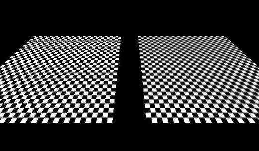
Figure 11-8. Aliasing artifacts on the right; the results of mipmapping on the left
We won’t go into the details of why aliasing happens; all you need to know is how to make objects look better. That’s where mipmapping comes in.
The key to fixing aliasing problems is to use lower-resolution images for the parts of an object that are smaller on screen or farther away from the view point. This is usually called a mipmap pyramid or chain. Given an image in its default resolution, say 256×256 pixels, we create smaller versions of it, dividing the sides by two for each level of the mipmap pyramid. Figure 11-9 shows the crate texture with various mipmap levels.

Figure 11-9. A mipmap chain
To make a texture mipmapped in OpenGL ES, we have to do two things:
Set the minification filter to one of the GL_XXX_MIPMAP_XXX constants, usually GL_LINEAR_MIPMAP_NEAREST.
Create the images for each mipmap chain level by resizing the original image and then upload them to OpenGL ES. The mipmap chain is attached to a single texture, not multiple textures.
To resize the base image for the mipmap chain, we can simply use the Bitmap and Canvas classes that the Android API provides. Let’s modify the Texture class a little. Listing 11-8 shows the code.
Listing 11-8. Texture.java: Our final version of the texture class
package com.badlogic.androidgames.framework.gl;import java.io.IOException;import java.io.InputStream;import javax.microedition.khronos.opengles.GL10;import android.graphics.Bitmap;import android.graphics.BitmapFactory;import android.graphics.Canvas;import android.graphics.Rect;import android.opengl.GLUtils;import com.badlogic.androidgames.framework.FileIO;import com.badlogic.androidgames.framework.impl.GLGame;import com.badlogic.androidgames.framework.impl.GLGraphics;public class Texture {GLGraphics glGraphics;FileIO fileIO;String fileName;int textureId;int minFilter;int magFilter;public int width;public int height;boolean mipmapped;
We add only one new member, called mipmapped, which stores whether the texture has a mipmap chain or not.
public Texture(GLGame glGame, String fileName) {this(glGame, fileName, false);}public Texture(GLGame glGame, String fileName, boolean mipmapped) {this.glGraphics = glGame.getGLGraphics();this.fileIO = glGame.getFileIO();this.fileName = fileName;this.mipmapped = mipmapped;load();}
For compatibility, we leave the old constructor in, which calls the new constructor. The new constructor takes a third argument that lets us specify whether we want the texture to be mipmapped.
private void load() {GL10 gl = glGraphics.getGL();int[] textureIds = new int[1];gl.glGenTextures(1, textureIds, 0);textureId = textureIds[0];InputStream in = null;try {in = fileIO.readAsset(fileName);Bitmap bitmap = BitmapFactory.decodeStream(in);if (mipmapped) {createMipmaps(gl, bitmap);} else {gl.glBindTexture(GL10.GL_TEXTURE_2D, textureId);GLUtils.texImage2D(GL10.GL_TEXTURE_2D, 0, bitmap, 0);setFilters(GL10.GL_NEAREST, GL10.GL_NEAREST);gl.glBindTexture(GL10.GL_TEXTURE_2D, 0);width = bitmap.getWidth();height = bitmap.getHeight();bitmap.recycle();}} catch (IOException e) {throw new RuntimeException("Couldn't load texture '" + fileName+ "'", e);} finally {if (in != null)try {in.close();} catch (IOException e) {}}}
The load() method stays essentially the same as well. The only addition is the call to createMipmaps()in case the texture should be mipmapped. Non-mipmapped Texture instances are created as before.
private void createMipmaps(GL10 gl, Bitmap bitmap) {gl.glBindTexture(GL10.GL_TEXTURE_2D, textureId);width = bitmap.getWidth();height = bitmap.getHeight();setFilters(GL10.GL_LINEAR_MIPMAP_NEAREST, GL10.GL_LINEAR);int level = 0;int newWidth = width;int newHeight = height;while (true) {GLUtils.texImage2D(GL10.GL_TEXTURE_2D, level, bitmap, 0);newWidth = newWidth / 2;newHeight = newHeight / 2;if (newWidth <= 0)break;Bitmap newBitmap = Bitmap.createBitmap(newWidth, newHeight,bitmap.getConfig());Canvas canvas = new Canvas(newBitmap);canvas.drawBitmap(bitmap,new Rect(0, 0, bitmap.getWidth(), bitmap.getHeight()),new Rect(0, 0, newWidth, newHeight), null);bitmap.recycle();bitmap = newBitmap;level++;}gl.glBindTexture(GL10.GL_TEXTURE_2D, 0);bitmap.recycle();}
The createMipmaps()method is fairly straightforward. We start off by binding the texture so that we can manipulate its attributes. The first thing we do is keep track of the bitmap’s width and height and set the filters. Note that we use GL_LINEAR_MIPMAP_NEAREST for the minification filter. If we don’t use that filter, mipmapping will not work and OpenGL ES will fall back to normal filtering, only using the base image.
The while loop is straightforward. We upload the current bitmap as the image for the current level. We start at level 0, the base level with the original image. Once the image for the current level is uploaded, we create a smaller version of it, dividing its width and height by 2. If the new width is less than or equal to 0, we can break out of the infinite loop, since we have uploaded an image for each mipmap level (the last image has a size of 1×1 pixels). We use the Canvas class to resize the image and to store the result in newBitmap. We then recycle the old bitmap so that we clean up any of the memory it used and set the newBitmap as the current bitmap. We repeat this process until the image is smaller than 1×1 pixels.
Finally, we unbind the texture and recycle the last bitmap that got created in the loop.
public void reload() {load();bind();setFilters(minFilter, magFilter);glGraphics.getGL().glBindTexture(GL10.GL_TEXTURE_2D, 0);}public void setFilters(int minFilter, int magFilter) {this.minFilter = minFilter;this.magFilter = magFilter;GL10 gl = glGraphics.getGL();gl.glTexParameterf(GL10.GL_TEXTURE_2D, GL10.GL_TEXTURE_MIN_FILTER,minFilter);gl.glTexParameterf(GL10.GL_TEXTURE_2D, GL10.GL_TEXTURE_MAG_FILTER,magFilter);}public void bind() {GL10 gl = glGraphics.getGL();gl.glBindTexture(GL10.GL_TEXTURE_2D, textureId);}public void dispose() {GL10 gl = glGraphics.getGL();gl.glBindTexture(GL10.GL_TEXTURE_2D, textureId);int[] textureIds = { textureId };gl.glDeleteTextures(1, textureIds, 0);}}
The rest of the class is the same as in the previous version. The only difference in usage is how we call the constructor. Since this is perfectly simple, we won’t write an example just for mipmapping. We’ll use mipmapping on all of the textures that we use for 3D objects. In 2D, mipmapping is less useful. A few final notes on mipmapping:
Mipmapping can increase performance quite a bit if the objects you draw using a mipmapped texture are small. The reason for this is that the GPU has to fetch fewer texels from smaller images in the mipmap pyramid. It’s therefore wise to always use mipmapped textures on objects that might get small.
A mipmapped texture takes up 33 percent more memory compared to an equivalent non-mipmapped version. This trade-off is usually fine.
Mipmapping only works with square textures in OpenGL ES 1.x. This is crucial to remember. If your objects stay white even though they are textured with a nice image, you can be pretty sure that you forgot about this limitation.
Note
Once again, because this is really important, remember that mipmapping will only work with square textures! A 512×256 pixel image will not work.
Simple Cameras
In the previous chapter, we talked about two ways to create a camera. The first one, the Euler camera, is similar to what is used in first-person shooters. The second one, the look-at camera, is used for cinematic camera work or for following an object. Let’s create two helper classes to create cameras that we can use in our games.
The First-Person, or Euler, Camera
The first-person, or Euler, camera is defined by the following attributes:
The field of view in degrees
The viewport aspect ratio
The near and far clipping planes
A position in 3D space
An angle around the y axis (yaw)
An angle around the x axis (pitch). This is limited to the range –90 to +90 degrees. Think how far you can tilt your own head and try to go beyond those angles! We are not responsible for any injuries.
The first three attributes are used to define the perspective projection matrix. We did this already with calls to gluPerspective() in all of our 3D examples.
The other three attributes define the position and orientation of the camera in our world. We will construct a matrix from this as outlined in Chapter 10.
We also want to be able to move the camera in the direction that it is heading. For this, we need a unit-length direction vector, and we can add this to the position vector of the camera. We can create this type of a vector with the help of the Matrix class that the Android API offers us. Let’s think about this for a moment.
In its default configuration, our camera will look down the negative z axis, giving it a direction vector of (0,0,–1). When we specify a yaw or pitch angle, this direction vector will be rotated accordingly. To figure out the direction vector, we just need to multiply it by a matrix that will rotate the default direction vector, just as OpenGL ES will rotate the vertices of our models.
Let’s have a look at how all this works in code. Listing 11-9 shows the EulerCamera class.
Listing 11-9. EulerCamera.java: A simple first-person camera based on Euler angles around the x and y axes
package com.badlogic.androidgames.framework.gl;import javax.microedition.khronos.opengles.GL10;import android.opengl.GLU;import android.opengl.Matrix;import com.badlogic.androidgames.framework.math.Vector3;public class EulerCamera {final Vector3 position = new Vector3();float yaw;float pitch;float fieldOfView;float aspectRatio;float near;float far;
The first three members hold the position and rotation angles of the camera. The other four members hold the parameters used for calculating the perspective projection matrix. By default, our camera is located at the origin of the world, looking down the negative z axis.
public EulerCamera(float fieldOfView, float aspectRatio, float near, float far){this.fieldOfView = fieldOfView;this.aspectRatio = aspectRatio;this.near = near;this.far = far;}
The constructor takes four parameters that define the perspective projection. We leave the camera position and rotation angles as they are.
public Vector3 getPosition() {return position;}public float getYaw() {return yaw;}public float getPitch() {return pitch;}
The getter methods just return the camera orientation and position.
public void setAngles(float yaw, float pitch) {if (pitch < -90)pitch = -90;if (pitch > 90)pitch = 90;this.yaw = yaw;this.pitch = pitch;}public void rotate(float yawInc, float pitchInc) {this.yaw += yawInc;this.pitch += pitchInc;if (pitch < -90)pitch = -90;if (pitch > 90)pitch = 90;}
The setAngles()method allows us to specify the yaw and pitch of the camera directly. Note that we limit the pitch to be in the range of –90 to 90. We can’t rotate our own head further than that, so our camera shouldn’t be able to do that either.
The rotate() method is nearly identical to the setAngles() method. Instead of setting the angles, it increases them by the parameters. This will be useful when we implement a little touchscreen-based control scheme in the next example.
public void setMatrices(GL10 gl) {gl.glMatrixMode(GL10.GL_PROJECTION);gl.glLoadIdentity();GLU.gluPerspective(gl, fieldOfView, aspectRatio, near, far);gl.glMatrixMode(GL10.GL_MODELVIEW);gl.glLoadIdentity();gl.glRotatef(-pitch, 1, 0, 0);gl.glRotatef(-yaw, 0, 1, 0);gl.glTranslatef(-position.x, -position.y, -position.z);}
The setMatrices() method just sets the projection and model-view matrices as discussed earlier. The projection matrix is set via gluPerspective() based on the parameters given to the camera in the constructor. The model-view matrix performs the world-moving trick we talked about in Chapter 10 by applying a rotation around the x and y axes as well as a translation. All involved factors are negated to achieve the effect where the camera remains at the origin of the world, looking down the negative z axis. We therefore rotate and translate the objects around the camera, not the other way around.
final float[] matrix = new float[16];final float[] inVec = { 0, 0, -1, 1 };final float[] outVec = new float[4];final Vector3 direction = new Vector3();public Vector3 getDirection() {Matrix.setIdentityM(matrix, 0);Matrix.rotateM(matrix, 0, yaw, 0, 1, 0);Matrix.rotateM(matrix, 0, pitch, 1, 0, 0);Matrix.multiplyMV(outVec, 0, matrix, 0, inVec, 0);direction.set(outVec[0], outVec[1], outVec[2]);return direction;}}
Finally, we have the mysterious getDirection() method. It is accompanied by a couple of final members that we use for the calculations inside the method. We do this so that we don’t allocate new float arrays and Vector3 instances each time the method is called. Consider those members to be temporary working variables.
Inside the method, we first set up a transformation matrix that contains the rotation around the x and y axes. We don’t need to include the translation, since we only want a direction vector, not a position vector. The direction of the camera is independent of its location in the world. The Matrix methods we invoke should be self-explanatory. The only strange thing is that we actually apply them in reverse order, without negating the arguments. We do the opposite in the setMatrices() method. That’s because we are now actually transforming a point in the same way that we’d transform our virtual camera, which does not have to be located at the origin or be oriented so that it looks down the negative z axis. The vector we rotate is (0,0,–1), stored in inVec. That’s the default direction of our camera if no rotation is applied. All that the matrix multiplications do is rotate this direction vector by the camera’s pitch and roll so that it points in the direction that the camera is heading. The last thing we do is set a Vector3 instance based on the result of the matrix-vector multiplication and return that to the caller. We can use this unit-length direction vector later on to move the camera in the direction it is heading.
Equipped with this little helper class, we can write a tiny example program that allows us to move through a world of crates.
An Euler Camera Example
We now want to use the EulerCamera class in a little program. We want to be able to rotate the camera up and down and left and right, based on swiping the touchscreen with a finger. We also want it to move forward when a button is pressed. Our world should be populated by a few dozen crates. Figure 11-10 shows the initial setup of our scene.
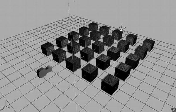
Figure 11-10. A simple scene with 25 crates, a point light, and an Euler camera in its initial position and orientation
The camera will be located at (0,1,3). We also have a white point light at (3,3,–3). The crates are positioned in a grid from –4 to 4 on the x axis and from 0 to –8 on the z axis, with a 2-unit distance between the centers.
How will we rotate the camera via swipes? We want the camera to rotate around the y axis when we swipe horizontally. That is equivalent to turning your head left and right. We also want the camera to rotate around the x axis when we swipe vertically. That’s equivalent to tilting your head up and down. We also want to be able to combine these two swipe motions. The most straightforward way to achieve this is to check whether a finger is on the screen and, if so, to measure the difference on each axis to the last known position of that finger on the screen. We can then derive a change in rotation on both axes by using the difference in x for the y-axis rotation and the difference in y for the x-axis rotation.
We also want to be able to move the camera forward by pressing an onscreen button. That’s simple; we just need to call EulerCamera.getDirection()and multiply its result by the speed at which we want the camera to move and the delta time so that we once again perform time-based movement. The only thing that we need to do is draw the button (we decided to draw a 64×64 button in the bottom-left corner of the screen) and check whether it is currently touched by a finger.
To simplify our implementation, we’ll only allow the user to either swipe-rotate or move. We could use the multitouch facilities for this, but that would complicate our implementation quite a bit.
With this plan of attack in place, let’s look at EulerCameraScreen, a GLScreen implementation contained in a GLGame implementation called EulerCameraTest (just the usual test structure). Listing 11-10 shows the code.
Listing 11-10. Excerpt from EulerCameraTest.java: The EulerCameraScreen
class EulerCameraScreen extends GLScreen {Texture crateTexture;Vertices3 cube;PointLight light;EulerCamera camera;Texture buttonTexture;SpriteBatcher batcher;Camera2D guiCamera;TextureRegion buttonRegion;Vector2 touchPos;float lastX = -1;float lastY = -1;
We start off with some members. The first two store the texture for the crate and the vertices of the texture cube. We’ll generate the vertices with the createCube() method from the previous example. The next member is a PointLight instance, which we are already familiar with, followed by an instance of our new EulerCamera class.
Next up are a couple of members we need to render the button. We use a separate 64×64 image called button.png for that button. To render it, we also need a SpriteBatcherinstance as well as a Camera2D instance and a TextureRegion instance. This means that we are going to combine 3D and 2D rendering in this example! The last three members are used to keep track of the current touchPos in the UI coordinate system (which is fixed to 480×320), as well as store the last known touch positions. We’ll use the value –1 for lastX and lastY to indicate that no valid last touch position is known yet.
public EulerCameraScreen(Game game) {super(game);crateTexture = new Texture(glGame, "crate.png", true);cube = createCube();light = new PointLight();light.setPosition(3, 3, -3);camera = new EulerCamera(67, glGraphics.getWidth() / (float)glGraphics.getHeight(), 1, 100);camera.getPosition().set(0, 1, 3);buttonTexture = new Texture(glGame, "button.png");batcher = new SpriteBatcher(glGraphics, 1);guiCamera = new Camera2D(glGraphics, 480, 320);buttonRegion = new TextureRegion(buttonTexture, 0, 0, 64, 64);touchPos = new Vector2();}
In the constructor, we load the crate texture and create the cube vertices as we did in the previous example. We also create a PointLight and set its position to (3,3,–3). The EulerCamera instance is created with the standard parameters: a 67-degree field of view, the aspect ratio of the current screen resolution, a near clipping plane distance of 1, and a far clipping plane distance of 100. Finally, we set the camera position to (0,1,3), as shown in Figure 11-10.
In the rest of the constructor, we just load the button texture and create the SpriteBatcher instance, Camera2D instance, and TextureRegion instance needed for rendering the button. Finally, we create a Vector2 instance so that we can transform real touch coordinates to the coordinate system of the Camera2D instance that we use for UI rendering, just as we did in Super Jumper in Chapter 9.
private Vertices3 createCube() {// same as in previous example}@Overridepublic void resume() {crateTexture.reload();}
The createCube() and resume() methods are exactly the same as in the previous example, so all the code isn’t repeated here.
@Overridepublic void update(float deltaTime) {game.getInput().getTouchEvents();float x = game.getInput().getTouchX(0);float y = game.getInput().getTouchY(0);guiCamera.touchToWorld(touchPos.set(x, y));if(game.getInput().isTouchDown(0)) {if(touchPos.x < 64 && touchPos.y < 64) {Vector3 direction = camera.getDirection();camera.getPosition().add(direction.mul(deltaTime));} else {if(lastX == -1) {lastX = x;lastY = y;} else {camera.rotate((x - lastX) / 10, (y - lastY) / 10);lastX = x;lastY = y;}}} else {lastX = -1;lastY = -1;}}
The update() method is where all the swipe rotation and movement happens based on touch events. The first thing we do is empty the touch event buffer via a call to Input.getTouchEvents(). Next, we fetch the current touch coordinates for the first finger on the screen. Note that if no finger is currently touching the screen, the methods we invoke will return the last known position of the finger with index 0. We also transform the real touch coordinates to the coordinate system of our 2D UI so that we can easily check whether the button in the bottom-left corner is pressed.
Equipped with all of these values, we then check whether a finger is actually touching the screen. If so, we first check whether it is touching the button, which spans the coordinates (0,0) to (64,64) in the 2D UI system. If that is the case, we fetch the current direction of the camera and add it to its position, multiplied by the current delta time. Since the direction vector is a unit-length vector, this means that the camera will move one unit per second.
If the button is not touched, we interpret the touch as a swipe gesture. For this to work, we need to have a valid last known touch coordinate. The first time the user puts his or her finger down, the lastX and lastY members will have a value of –1, indicating that we can’t create a difference between the last and current touch coordinates because we only have a single data point. Therefore, we just store the current touch coordinates and return from the update() method. If we recorded touch coordinates the last time update() was invoked, we simply take the difference on the x and y axes between the current and the last touch coordinates. We directly translate these into increments of the rotation angles. To slow down the rotation a little, we divide the differences by 10. The only thing left is to call the EulerCamera.rotate() method, which will adjust the rotation angles accordingly.
Finally, if no finger is currently touching the screen, we set the lastX and lastY members to –1 to indicate that we have to await the first touch event before we can do any swipe-gesture processing.
@Overridepublic void present(float deltaTime) {GL10 gl = glGraphics.getGL();gl.glClear(GL10.GL_COLOR_BUFFER_BIT | GL10.GL_DEPTH_BUFFER_BIT);gl.glViewport(0, 0, glGraphics.getWidth(), glGraphics.getHeight());camera.setMatrices(gl);gl.glEnable(GL10.GL_DEPTH_TEST);gl.glEnable(GL10.GL_TEXTURE_2D);gl.glEnable(GL10.GL_LIGHTING);crateTexture.bind();cube.bind();light.enable(gl, GL10.GL_LIGHT0);for(int z = 0; z >= -8; z-=2) {for(int x = -4; x <=4; x+=2 ) {gl.glPushMatrix();gl.glTranslatef(x, 0, z);cube.draw(GL10.GL_TRIANGLES, 0, 6 * 2 * 3);gl.glPopMatrix();}}cube.unbind();gl.glDisable(GL10.GL_LIGHTING);gl.glDisable(GL10.GL_DEPTH_TEST);gl.glEnable(GL10.GL_BLEND);gl.glBlendFunc(GL10.GL_SRC_ALPHA, GL10.GL_ONE_MINUS_SRC_ALPHA);guiCamera.setViewportAndMatrices();batcher.beginBatch(buttonTexture);batcher.drawSprite(32, 32, 64, 64, buttonRegion);batcher.endBatch();gl.glDisable(GL10.GL_BLEND);gl.glDisable(GL10.GL_TEXTURE_2D);}
The present() method is surprisingly simple, thanks to the work we put into all of those little helper classes. We start off with the usual things like clearing the screen and setting the viewport. Next, we tell the EulerCamera instance to set the projection matrix and model-view matrix. From this point on, we can render anything that should be 3D onscreen. Before we do that, we enable depth testing, texturing, and lighting. Next, we bind the crate texture and the cube vertices and also enable the point light. Note that we bind the texture and cube vertices only once, since we are going to reuse them for all of the crates that we render. This is the same trick that we used in our BobTest in Chapter 8 when we wanted to speed up rendering by reducing state changes.
The next piece of code just draws the 25 cubes in a grid formation via a simple nested for loop. Since we have to multiply the model-view matrix by a translation matrix in order to put the cube vertices at a specific position, we must also use glPushMatrix() and glPopMatrix() so that we don’t destroy the camera matrix that’s also stored in the model-view matrix.
Once we are done with rendering our cubes, we unbind the cube vertices and disable lighting and depth testing. This is crucial, since we are now going to render the 2D UI overlay with the button. Since the button is actually circular, we also enable blending to make the edges of the texture transparent.
Rendering the button is done in the same way that we rendered the UI elements in Super Jumper. We tell the Camera2D instance to set the viewport and matrices (we wouldn’t really need to set the viewport here again; feel free to “optimize” this method) and tell the SpriteBatcher that we are going to render a sprite. We render the complete button texture at (32,32) in our 480×320 coordinate system that we set up via the guiCamera instance.
Finally, we just disable the last few states we enabled previously: blending and texturing.
@Overridepublic void pause() {}@Overridepublic void dispose() {}}
The rest of the class is again just some stub methods for pause() and dispose(). Figure 11-11 shows the output of this little program.
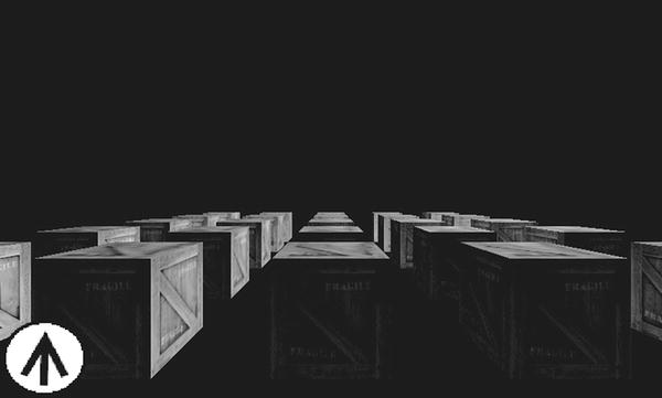
Figure 11-11. A simple example of first-person-shooter controls, without multitouch for simplicity
Pretty nice, right? It also doesn’t take a lot of code, either, thanks to the wonderful job our helper classes do for us. Now, adding multitouch support would be awesome, of course. Here’s a hint: instead of using polling, as in the example just seen, use the actual touch events. On a “touch down” event, check whether the button was hit. If so, mark the pointer ID associated with it as not being able to produce swipe gestures until a corresponding “touch up” event is signaled. Touch events from all other pointer IDs can be interpreted as swipe gestures!
A Look-At Camera
The second type of camera usually found in games is a simple look-at camera. It is defined by the following:
A position in space
An up vector. Think of this as an arrow that you would see if you slapped a “This Side Up” sticker on the back of the camera when your camera is sitting flat on a level surface.
A look-at position in space or, alternatively, a direction vector. We’ll use the former.
A field of view in degrees
A viewport aspect ratio
A near clipping plane distance and a far clipping plane distance
The only difference between a look-at camera and the Euler camera is the way we encode the orientation of the camera. In this case, we specify the orientation by the up vector and the look-at position. Let’s write a helper class for this type of camera. Listing 11-11 shows the code.
Listing 11-11. LookAtCamera.java: A simple look-at camera without bells and whistles
package com.badlogic.androidgames.framework.gl;import javax.microedition.khronos.opengles.GL10;import android.opengl.GLU;import com.badlogic.androidgames.framework.math.Vector3;public class LookAtCamera {final Vector3 position;final Vector3 up;final Vector3 lookAt;float fieldOfView;float aspectRatio;float near;float far;public LookAtCamera(float fieldOfView, float aspectRatio, float near, float far) {this.fieldOfView = fieldOfView;this.aspectRatio = aspectRatio;this.near = near;this.far = far;position = new Vector3();up = new Vector3(0, 1, 0);lookAt = new Vector3(0,0,-1);}public Vector3 getPosition() {return position;}public Vector3 getUp() {return up;}public Vector3 getLookAt() {return lookAt;}public void setMatrices(GL10 gl) {gl.glMatrixMode(GL10.GL_PROJECTION);gl.glLoadIdentity();GLU.gluPerspective(gl, fieldOfView, aspectRatio, near, far);gl.glMatrixMode(GL10.GL_MODELVIEW);gl.glLoadIdentity();GLU.gluLookAt(gl, position.x, position.y, position.z, lookAt.x, lookAt.y, lookAt.z, up.x, up.y, up.z);}}
There are no real surprises here. We just store the position, up, and lookAt values as Vector3 instances, along with the perspective projection parameters we also had in the EulerCamera class. In addition, we provide a couple of getters so that we can modify the attributes of the camera. The only interesting method is setMatrices(), but even that is old hat for us. We first set the projection matrix to a perspective projection matrix based on the field of view, aspect ratio, and near and far clipping plane distances. Then, we set the model-view matrix to contain the camera position and orientation matrix via gluLookAt(), as discussed in Chapter 10. This will actually produce a matrix very similar to the matrix we “handcrafted” in the EulerCamera example. It will also rotate the objects around the camera, instead of the other way around. However, the nice interface of the gluLookAt() method shields us from all those silly things like inverting positions or angles.
We could, in fact, use this camera just like a EulerCamera instance . All we need to do is create a direction vector by subtracting the camera’s position from its look-at point and normalizing it. Then, we just rotate this direction vector by the yaw and pitch angles. Finally, we set the new look-at position to the position of the camera and add the direction vector. Both methods would produce exactly the same transformation matrix. It’s just two different ways to handle camera orientation.
We’ll refrain from writing an explicit example for the LookAtCamera class, since the interface is perfectly simple. We’ll use it in our last game in this book, where we let it follow a neat little spaceship! If you want to play around with it a little, add it to the LightTest we wrote earlier or modify the EulerCameraTest in such a way that the LookAtCamera class can be used like a first-person-shooter camera, as outlined in the previous paragraph.
Loading Models
Defining models like our cube in code is very cumbersome, to say the least. A better way to create these types of models is to use special software that allows WYSIWYG creation of complex forms and objects. There’s a plethora of software available for this task:
Blender, an open source project used in many game and movie productions. It’s very capable and flexible, but also a bit intimidating.
Wings3D, our weapon of choice and also open source. We use it for simple low-poly (read: not many triangles) modeling of static objects. It’s very simplistic but gets the job done.
3D Studio Max, one of the de facto standards in the industry. It’s a commercial product, but there are student versions available.
Maya, another industry favorite. It’s also a commercial product but has some pricing options that might fit smaller purses.
That’s just a selection of the more popular options out in the wild. Teaching you how to use one of these is well outside the scope of this book. However, no matter what software you use, at some point you will save your work to some kind of format. One such format is Wavefront OBJ, a very old plain-text format that can easily be parsed and translated to one of our Vertices3 instances.
The Wavefront OBJ Format
We will implement a loader for a subset of this format. Our loader will support models that are composed of triangles only and that optionally may contain texture coordinates and normals. The OBJ format also supports the storage of arbitrary convex polygons, but we won’t go into that. Whether you simply find an OBJ model or create your own, just make sure that it is triangulated—meaning that it’s composed of triangles only.
The OBJ format is line based. Here are the parts of the syntax we are going to process:
v x y z: The v indicates that the line encodes a vertex position, while x, y, and z are the coordinates encoded as floating-point numbers.
vn i j k: The vn indicates that the line encodes a vertex normal, with i, j, and k being the x, y, and z components of the vertex normal.
vt u v: The vt indicates that the line encodes a texture coordinate pair, with u and v being the texture coordinates.
f v1/vt1/vn1 v2/vt2/vn2 v3/vt3/vn3: The f indicates that the line encodes a triangle. Each of the v/vt/vn blocks contains the indices of the position, texture coordinates, and vertex normal of a single vertex of the triangle. The indices are relative to the vertex positions, texture coordinates, and vertex normal defined previously by the other three line formats. The vt and vn indices can be left out to indicate that there are no texture coordinates or normals for a specific vertex of a triangle.
We will ignore any line that does not start with v, vn, vt, or f; we will also output an error if any of the permissible lines don’t follow the formatting just described. Items within a single line are delimited by whitespaces, which can include spaces, tabs, and so on.
Note
The OBJ format can store a lot more information than we are going to parse here. We can get away with only parsing the syntax shown here and ignoring anything else as long as the models are triangulated and have normal and texture coordinates.
Here’s a very simple example of a texture triangle with normals in OBJ format:
v -0.5 -0.5 0v 0.5 -0.5 0v 0 0.5 0vn 0 0 1vn 0 0 1vn 0 0 1vt 0 1vt 1 1vt 0.5 0f 1/1/1 2/2/2 3/3/3
Note that the vertex positions, texture coordinates, and normals do not have to be defined in such a nice order. They could be intertwined if the software that saved the file chose to do so.
The indices given in an f statement are one-based, rather than zero-based (as in the case of a Java array). Some software even outputs negative indices at times. This is permitted by the OBJ format specification but is a major pain. We have to keep track of how many vertex positions, texture coordinates, or vertex normals we have loaded so far and then add that negative index to the respective number of positions, vertex coordinates, or normals, depending on what vertex attribute that index is indicating.
Implementing an OBJ Loader
Our plan of attack will be to load the file completely into memory and to create a string per line. We will also create temporary float arrays for all of the vertex positions, texture coordinates, and normals that we are going to load. Their size will be equal to the number of lines in the OBJ file times the number of components per attribute; that is, two for texture coordinates or three for normals. By doing this, we overshoot the necessary amount of memory needed to store the data, but that’s still better than allocating new arrays every time we have filled them up.
We also do the same for the indices that define each triangle. While the OBJ format is indeed an indexed format, we can’t use those indices directly with our Vertices3 class. The reason for this is that a vertex attribute might be reused by multiple vertices, so there’s a one-to-many relationship that is not allowed in OpenGL ES. Therefore, we’ll use a nonindexed Vertices3 instance and simply duplicate the vertices. For our needs, that’s OK.
Let’s see how we can implement all of this. Listing 11-12 shows the code.
Listing 11-12. ObjLoader.java: A simple class for loading a subset of the OBJ format
package com.badlogic.androidgames.framework.gl;import java.io.BufferedReader;import java.io.IOException;import java.io.InputStream;import java.io.InputStreamReader;import java.util.ArrayList;import java.util.List;import com.badlogic.androidgames.framework.impl.GLGame;public class ObjLoader {public static Vertices3 load(GLGame game, String file) {InputStream in = null;try {in = game.getFileIO().readAsset(file);List<String> lines = readLines(in);float[] vertices = new float[lines.size()* 3];float[] normals = new float[lines.size()* 3];float[] uv = new float[lines.size()* 2];int numVertices = 0;int numNormals = 0;int numUV = 0;int numFaces = 0;int[] facesVerts = new int[lines.size() * 3];int[] facesNormals = new int[lines.size() * 3];int[] facesUV = new int[lines.size() * 3];int vertexIndex = 0;int normalIndex = 0;int uvIndex = 0;int faceIndex = 0;
The first thing we do is open an InputStream to the asset file specified by the file parameter. We then read in all of the lines of that file using a method called readLines()(defined in the code that follows). Based on the number of lines, we allocate float arrays that will store the x, y, and z coordinates of each vertex’s position; the x, y, and z components of each vertex’s normal; and the u and v components of each vertex’s texture coordinates. Since we don’t know how many vertices there are in the file, we just allocate more space than needed for the arrays. Each vertex attribute is stored in subsequent elements of the three arrays. The position of the first read vertex is in vertices[0], vertices[1], and vertices[2], and so on. We also keep track of the indices in the triangle definitions for each of the three attributes of a vertex. In addition, we have a couple of counters to keep track of how many things we have already loaded.
for (int i = 0; i < lines.size(); i++) {String line = lines.get(i);
Next, we have a for loop that iterates through all the lines in the files.
if (line.startsWith("v ")) {String[] tokens = line.split("[ ]+");vertices[vertexIndex] = Float.parseFloat(tokens[1]);vertices[vertexIndex + 1] = Float.parseFloat(tokens[2]);vertices[vertexIndex + 2] = Float.parseFloat(tokens[3]);vertexIndex += 3;numVertices++;continue;}
If the current line is a vertex position definition, we split the line by whitespaces, read the x, y, and z coordinates, and store it in the vertices array.
if (line.startsWith("vn ")) {String[] tokens = line.split("[ ]+");normals[normalIndex] = Float.parseFloat(tokens[1]);normals[normalIndex + 1] = Float.parseFloat(tokens[2]);normals[normalIndex + 2] = Float.parseFloat(tokens[3]);normalIndex += 3;numNormals++;continue;}if (line.startsWith("vt")) {String[] tokens = line.split("[ ]+");uv[uvIndex] = Float.parseFloat(tokens[1]);uv[uvIndex + 1] = Float.parseFloat(tokens[2]);uvIndex += 2;numUV++;continue;}
We do the same thing for the normals and texture coordinates .
if (line.startsWith("f ")) {String[] tokens = line.split("[ ]+");String[] parts = tokens[1].split("/");facesVerts[faceIndex] = getIndex(parts[0], numVertices);if (parts.length > 2)facesNormals[faceIndex] = getIndex(parts[2], numNormals);if (parts.length > 1)facesUV[faceIndex] = getIndex(parts[1], numUV);faceIndex++;parts = tokens[2].split("/");facesVerts[faceIndex] = getIndex(parts[0], numVertices);if (parts.length > 2)facesNormals[faceIndex] = getIndex(parts[2], numNormals);if (parts.length > 1)facesUV[faceIndex] = getIndex(parts[1], numUV);faceIndex++;parts = tokens[3].split("/");facesVerts[faceIndex] = getIndex(parts[0], numVertices);if (parts.length > 2)facesNormals[faceIndex] = getIndex(parts[2], numNormals);if (parts.length > 1)facesUV[faceIndex] = getIndex(parts[1], numUV);faceIndex++;numFaces++;continue;}}
In this code, each vertex of a triangle (here called a face, as that is the term used in the OBJ format) is defined by a triplet of indices into the vertex position, texture coordinate, and normal arrays. The texture coordinate and normal indices can be omitted, so we keep track of this. The indices can also be negative, in which case we have to add them to the number of positions/texture coordinates/normals loaded so far. That’s what the getIndex() method does for us.
float[] verts = new float[(numFaces * 3)* (3 + (numNormals > 0 ? 3 : 0) + (numUV > 0 ? 2 : 0))];
Once we have loaded all vertex positions, texture coordinates, normals, and triangles, we can start assembling a float array that holds the vertices in the format expected by a Vertices3 instance. The number of floats needed to store these vertices can easily be derived from the number of triangles we loaded and whether normal and texture coordinates are given.
for (int i = 0, vi = 0; i < numFaces * 3; i++) {int vertexIdx = facesVerts[i] * 3;verts[vi++] = vertices[vertexIdx];verts[vi++] = vertices[vertexIdx + 1];verts[vi++] = vertices[vertexIdx + 2];if (numUV > 0) {int uvIdx = facesUV[i] * 2;verts[vi++] = uv[uvIdx];verts[vi++] = 1 - uv[uvIdx + 1];}if (numNormals > 0) {int normalIdx = facesNormals[i] * 3;verts[vi++] = normals[normalIdx];verts[vi++] = normals[normalIdx + 1];verts[vi++] = normals[normalIdx + 2];}}
To fill the verts array, we just loop over all the triangles, fetch the vertex attribute for each vertex of a triangle, and put them into the verts array in the layout we usually use for a Vertices3 instance.
Vertices3 model = new Vertices3(game.getGLGraphics(), numFaces * 3,0, false, numUV > 0, numNormals > 0);model.setVertices(verts, 0, verts.length);return model;
The last thing we do is instantiate the Vertices3 instance and set the vertices.
} catch (Exception ex) {throw new RuntimeException("couldn't load '" + file + "'", ex);} finally {if (in != null)try {in.close();} catch (Exception ex) {}}}
The rest of the method just does some exception handling and closing of the InputStream.
static int getIndex(String index, int size) {int idx = Integer.parseInt(index);if (idx < 0)return size + idx;elsereturn idx - 1;}
The getIndex() method takes one of the indices given for an attribute of a vertex in a triangle definition, as well as the number of attributes loaded so far, and returns a suitable index to reference the attribute in one of our working arrays.
static List<String> readLines(InputStream in) throws IOException {List<String> lines = new ArrayList<String>();BufferedReader reader = new BufferedReader(new InputStreamReader(in));String line = null;while ((line = reader.readLine()) != null)lines.add(line);return lines;}}
Finally, there’s the readLines() method, which just reads in each line of a file and returns all these lines as a List of strings.
To load an OBJ file from an asset, we can use the ObjLoader as follows:
Vertices3 model = ObjLoader.load(game, "mymodel.obj");Pretty straightforward after all of this index juggling, right? To render this Vertices3 instance, we need to know how many vertices it has, though. Let’s extend the Vertices3 class one more time, adding two methods to return the number of vertices and the number of indices currently defined in the instance. Listing 11-13 shows the code.
Listing 11-13. Excerpt from Vertices3.java: Fetching the number of vertices and indices
public int getNumIndices() {return indices.limit();}public int getNumVertices() {return vertices.limit()/ (vertexSize / 4);}
For the number of indices, we just return the limit of the ShortBuffer storing the indices. For the number of vertices, we do the same. However, since the limit is reported in the number of floats defined in the FloatBuffer, we have to divide it by the vertex size. Since we store that in number of bytes in vertexSize, we divide vertexSize by 4.
Using the OBJ Loader
To demonstrate the OBJ loader, let’s rewrite the previous example and create a new test called ObjTest along with an ObjScreen. Copy over all the code from the previous example and only change the line in the constructor of the ObjScreen class that’s responsible for creating the cube:
cube = ObjLoader.load(glGame, "cube.obj");Instead of using the createCube() method (which we removed), we are now directly loading a model from an OBJ file, called cube.obj. We created a replica of the cube we previously specified programmatically in createCube() in Wings3D. You can find it in the SVN repository just like all other assets. It has the same vertex positions, texture coordinates, and normals as the handcrafted version. It should come as no surprise that, when you run ObjTest, it will look exactly like our EulerCameraTest. We’ll therefore spare you the obligatory screenshot.
Some Notes on Loading Models
For the game we are going to write in the next chapter, our loader is sufficient, but it is far from robust. There are some caveats:
String processing in Android is inherently slow. The OBJ format is a plain-text format and, as such, it needs a lot of parsing. This will have a negative influence on load times. We can work around this issue by converting our OBJ models to a custom binary format. We could, for example, just serialize the verts array that we fill in the ObjLoader.load() method.
The OBJ format has a lot more features that we don’t exploit. If you want to extend our simple loader, look up the format specification on the Web. It should be easy to add more functionality.
An OBJ file is usually accompanied by what’s called a material file. This file defines the colors and textures to be used by groups of vertices in the OBJ file. We will not need this functionality since we know which texture to use for a specific OBJ file. For a more robust loader, you’ll want to look into the material file specification as well.
A Little Physics in 3D
In Chapter 8, we developed a very simple point mass–based physics model in 2D. Here’s the good news: everything works the same in 3D!
Positions are now 3D vectors instead of 2D vectors. We just add a z coordinate.
Velocities are still expressed in meters per second on each axis. We just add one more component for the z axis!
Accelerations are also still expressed in meters per second squared (m/s2) on each axis. Again, we just add another coordinate.
In Chapter 8, the pseudocode with which we described a physics simulation update looked like this:
Vector2 position = new Vector2();Vector2 velocity = new Vector2();Vector2 acceleration = new Vector2(0, -10);while(simulationRuns) {float deltaTime = getDeltaTime();velocity.add(acceleration.x * deltaTime, acceleration.y * deltaTime);position.add(velocity.x * deltaTime, velocity.y * deltaTime);}
We can translate this into 3D space by simply exchanging the Vector2 instances with Vector3 instances:
Vector3 position = new Vector3();Vector3 velocity = new Vector3();Vector3 acceleration = new Vector3(0, -10, 0);while(simulationRuns) {float deltaTime = getDeltaTime();velocity.add(acceleration.x * deltaTime, acceleration.y * deltaTime, acceleration.z * deltaTime);position.add(velocity.x * deltaTime, velocity.y * deltaTime, velocity.z * deltaTime);}
And that is all there is to it! This simple physics model is again sufficient for many simple 3D games. In the final game of this book, we will not even use any acceleration because of the nature of the objects in the game.
More complex physics in 3D (and 2D) are, of course, harder to implement. For this purpose, you’d usually want to use a third-party library instead of reinventing the wheel yourself. The problem on Android is that Java-based solutions will be much too slow because of the heavy computations involved. There are some solutions for 2D physics for Android that wrap native C++ libraries like Box2D via the Java Native Interface (JNI), providing the native API to a Java application. For 3D physics, there’s a library called Bullet. However, there aren’t any usable JNI bindings for this library yet. These topics are well outside of the scope of this book, though, and in many cases we don’t need any sophisticated rigid-body physics.
Collision Detection and Object Representation in 3D
In Chapter 8, we discussed the relationship between object representation and collision detection. We strive to make our game-world objects as independent from their graphical representation as possible. Instead, we’d like to define them in terms of their bounding shape, position, and orientation. Position and orientation are not much of a problem; we can express the former as a Vector3 instance and the latter as the rotation around the x, y, and z axes (minding the potential gimbal-lock problem mentioned in Chapter 10). Let’s take a look at bounding shapes, however.
Bounding Shapes in 3D
In terms of bounding shapes, as with 2D programming, we again have a ton of options. Figure 11-12 shows some of the more popular bounding shapes in 3D programming.
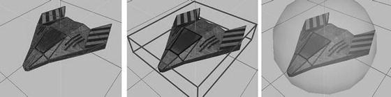
Figure 11-12. Various bounding shapes. From left to right: triangle mesh, axis-aligned bounding box, and bounding sphere.
Triangle mesh: This bounds the object as tightly as possible. However, colliding two objects based on their triangle meshes is computationally heavy.
Axis-aligned bounding box: This bounds the object loosely. It is a lot less computationally intensive than a triangle mesh.
Bounding sphere: This bounds the object even less well. It is the fastest way to check for collisions, though.
Another problem with triangle meshes and bounding boxes is that we have to reorient them whenever we rotate or scale the object, just as in 2D. Bounding spheres, on the other hand, don’t need any modification if we rotate an object. If we scale an object, we just need to scale the radius of the sphere, which is a simple multiplication issue.
Bounding Sphere Overlap Testing
The mathematics of triangle mesh and bounding box collision detection can be pretty involved. For our next game, bounding spheres will do just fine. There’s also a little trick we can apply that we already used in Super Jumper: to make the bounding sphere fit a little better, we make it smaller than the graphical representation. Figure 11-13 shows how that could look in the case of a spaceship.

Figure 11-13. Making the bounding sphere smaller to better fit an object
That’s, of course, a very cheap trick, but it turns out that, in many situations, it is more than sufficient to keep up the illusion of mostly correct collision detection.
So, how do we collide two spheres with each other? Or rather, how do we test for overlap? It works exactly the same as in the case of circles! All we need to do is measure the distance from the center of one sphere to the center of the other sphere. If that distance is smaller than the two radii of the spheres added together, then we have a collision. Let’s create a simple Sphere class. Listing 11-14 shows the code.
Listing 11-14. Sphere.java: A simple bounding sphere
package com.badlogic.androidgames.framework.math;public class Sphere {public final Vector3 center = new Vector3();public float radius;public Sphere(float x, float y, float z, float radius) {this.center.set(x,y,z);this.radius = radius;}}
That’s the same code that we used in the Circle class in Chapter 8. All we changed is the vector holding the center, which is now a Vector3 instead of a Vector2.
Let’s also extend our OverlapTester class with methods to check for the overlap of two spheres and to test whether a point is inside a sphere. Listing 11-15 shows the code.
Listing 11-15. Excerpt from OverlapTester.java: Adding sphere-testing methods
public static boolean overlapSpheres(Sphere s1, Sphere s2) {float distance = s1.center.distSquared(s2.center);float radiusSum = s1.radius + s2.radius;return distance <= radiusSum * radiusSum;}public static boolean pointInSphere(Sphere c, Vector3 p) {return c.center.distSquared(p) < c.radius * c.radius;}public static boolean pointInSphere(Sphere c, float x, float y, float z) {return c.center.distSquared(x, y, z) < c.radius * c.radius;}
That’s again exactly the same code as in the case of circle overlap testing. We just use the center of the spheres, which are Vector3 instances instead of Vector2 instances, as in the case of a circle.
Note
Entire books have been filled on the topic of 3D collision detection. If you want to dive deeper into that rather interesting world, we suggest the book Real-Time Collision Detectionby Christer Ericson (Morgan Kaufmann, 2005). It should be on the shelf of any self-respecting game developer!
GameObject3D and DynamicGameObject3D
Now that we have a nice bounding shape for our 3D objects, we can easily write the equivalent of the GameObject and DynamicGameObject classes we used in 2D. We just replace any Vector2 instance with a Vector3 instance and use the Sphere class instead of the Rectangle class. Listing 11-16 shows the GameObject3D class.
Listing 11-16. GameObject3D.java: Representing a simple object with a position and bounds
package com.badlogic.androidgames.framework;import com.badlogic.androidgames.framework.math.Sphere;import com.badlogic.androidgames.framework.math.Vector3;public class GameObject3D {public final Vector3 position;public final Sphere bounds;public GameObject3D(float x, float y, float z, float radius) {this.position = new Vector3(x,y,z);this.bounds = new Sphere(x, y, z, radius);}}
This code is so trivial that you probably don’t need any explanation. The only hitch is that we have to store the same position twice: once as the position member in the GameObject3Dclass, and again within the position member of the Sphere instance that’s contained in the GameObject3D class. This is somewhat ugly, but, for the sake of clarity, we’ll stick to it.
Deriving a DynamicGameObject3D class from this class is also simple. Listing 11-17 shows the code.
Listing 11-17. DynamicGameObject3D.java: The dynamic equivalent to GameObject3D
package com.badlogic.androidgames.framework;import com.badlogic.androidgames.framework.math.Vector3;public class DynamicGameObject3D extends GameObject3D {public final Vector3 velocity;public final Vector3 accel;public DynamicGameObject3D(float x, float y, float z, float radius) {super(x, y, z, radius);velocity = new Vector3();accel = new Vector3();}}
We again just replace any Vector2 instance with a Vector3 instance and smile happily.
In 2D, we had to think hard about the relationship between the graphical representation of our objects (given in pixels) and the units used within the model of our world. In 3D, we can break free from this! The vertices of our 3D models that we load from, say, an OBJ file can be defined in whatever unit system we want. We no longer need to transform pixels to world units and vice versa. This makes working in 3D a little easier. We just need to train our artist so that he or she provides us with models that are properly scaled to the unit system of our world.
Summary
We have again uncovered a lot of mysteries in the world of game programming. We talked a little bit about vectors in 3D, which turned out to be as simple to use as their 2D counterparts. The general theme is as follows: just add a z coordinate! We also took a look at lighting in OpenGL ES. With the helper classes we wrote to represent materials and light sources, it is pretty simple to set up the lighting in a scene. For better performance and fewer graphical artifacts, we also implemented simple mipmapping as part of our Texture class. We also explored the implementation of simple Euler and look-at cameras, using very little code and a little help from the Matrix class to do so.
Since the creation of 3D meshes by hand in code is tedious, we also looked at one of the simplest and most popular 3D file formats: Wavefront OBJ. We revisited our simple physics model and transferred it to the realm of 3D, which turned out to be as simple as creating 3D vectors.
The last point on our agenda was to figure out how to cope with bounding shapes and object representation in 3D. Given our modest needs, we arrived at very simple solutions for both problems, which are very similar or even identical to those we used in 2D.
While there is a lot more to 3D programming than we can present here, you now have a pretty good idea about what is needed in order to write a 3D game. The big realization is that there is not a lot of difference between a 2D game and a 3D game (up to a certain degree of complexity, of course). We don’t have to be afraid of 3D anymore! In Chapter 12, we’ll use our new knowledge to write the final game of this book: Droid Invaders!