![]()
Creating Visuals, Making Sounds, and Using Data on the EV3 Brick
Since I already discussed how to connect the motors to the EV3 Brick to make things happen in the last chapter, I think it is time that I discuss the particulars about sight, sound, and lights on the EV3 brick. This is somewhat complex, and I wanted to devote an entire chapter to this.
While discussing the display, sound, and Brick Status Light, I thought I would spend part of this chapter discussing the importance of the data operations, or red programming blocks. Data operation blocks can do a lot of things, but sometimes the results will not be as visible as the programs for the model in Chapter 3. As their name implies, the data operations blocks will be performing highly complex data processing and mathematics, and the results may not be seen unless the program asks. This is the reason I chose to discuss the data blocks in the same chapter as the display, because you can program the display to show you what the data operation blocks have achieved.
The Display programming block is capable of creating a graphic to be shown on the screen, and even though the screen is not in color, it does have good resolution. You will see that the Display block has four modes: Text, Shapes, Image, and Reset Screen that you can see in Figure 4-1.
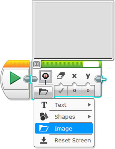
Figure 4-1. The four modes of the Display programming block, along with the Preview
You will notice that when you switch modes, this will change the parameters for each, but the one constant is the preview that you can access by clicking on the left-hand corner. You will see it underneath the big blank section in Figure 4-2.
Text
Text allows you to create words, and the bar on the right-hand corner allows you to type in whatever text that you want to put on the EV3 Brick display, provided it fills only one line on the display preview. This is a maximum of 21 characters with the smallest font provided, and 11 characters with the largest. Unfortunately, the program does not allow you to do more than one line per Display programming block. If you want to have more than one line on the screen, see Figure 4-3.
You will also notice that an option that says “Wired”, and this is when you want to wire your text in from another programming block, which I explained in Chapter 3. I will have a demonstration of that later in this chapter when I discuss the variable data operation block.
Some of your options include Pixels and Grid, and you can see examples of both of those sub modes and parameters of Text in Figure 4-2.

Figure 4-2. Three examples of Text on a Display
Examples A and B in Figure 4-2 are in Pixel mode, which means that it will essentially give a blank background in the example as opposed to the Grid mode. You can see in Example C that the text is on a grid, which is very helpful in spacing words on the display screen. Please note that when you run the program on the EV3 Brick, the grid will not be seen.
Now I will talk about the other parameters.
- The first is the True and False option under the clear screen, which does exactly as it says. You may notice that it says “MINDSTORMS” and “Program” every time you run any program on the LEGO EV3 Brick. By setting the value to “Clear Screen True” you ensure that you don’t see the “MINDSTORMS Program” when you run your program. You can see this demonstrated in Examples A and C, which means that you will see exactly what is on the previews when you run the program. Example B will print the words on whatever is on the screen. The Clear Screen is also useful for when you want to have multiple lines on one display screen, as the example shows in Figure 4-3.
- The X and Y parameters control the horizontal (x) and the vertical (y). You will notice that there are bar controls to adjust the length and width of the placement of the words. In the Pixel mode, the text moves pixels and has a large range (–177 to 177 for x and –127 to 127 for y). In the grid mode, you can adjust from 0 to 21 on X and 0 to 12 on y. Example A has coordinates at 0, 0, which insures the words are up and to the left. Example B puts the words on the bottom with (63,116). Example C uses the grid to place it at 3, 5, and the parameter values center the text. You will note that negative numbers can be used, as well as decimals. The problem is you might even put the words so far off the screen that they won’t be seen.
- As for the Color, it is possible to make it be white on black or black on white. Examples A and B are in black, while Example C has the white on black look. All that is required is to set the color to White or False.
- There are only three options for the Font Size: 0, 1, and 2. I call them Small, Medium, and Large, and examples of them are respectively in Examples A, B, and C.

Figure 4-3. A way of displaying multiple lines using the Display programming blocks
This mode allows you to make shapes on the screen; the ones that you can make are geometric such as the line, circle, rectangle, and point. Like the text program, it is possible to make more than one shape on the screen at once, with the proper use of “Clear Screen”. I will demonstrate how to do that later, but for now, I want to explain the parameters of each shape individually.
Line
This is for creating your basic straight line segment that will appear on the screen. You will notice that, like the text option, there are options for x and y that show where the line begins and ends. You can also see that you can change the color of the line as well, but I have discovered that changing it to white makes the line difficult to see on the display. You can see that it requires setting parameters and you can see some examples in Figure 4-4.

Figure 4-4. Examples of making lines on the display
Making a line segment is about setting one point for the beginning (x1, y1) and another point for the ending (x2, y2). You can see that by altering the coordinates how it changes the slope of the line as well as the length.
Circle
With the text making a circle, you first establish where the center is, and then establish a radius. You then have to choose if you want the circle filled and the color. You can see examples of this in Figure 4-5.

Figure 4-5. Examples of circles on the program
You will note that in some of the examples, the center is off the screen. In some cases, the entire circle is visible.
Rectangle
This allows you to make rectangles by beginning with the X and Y point of origin. You can adjust the length and width of these rectangles by increasing or decreasing its size as well as filling it in. You can see some examples in Figure 4-6.
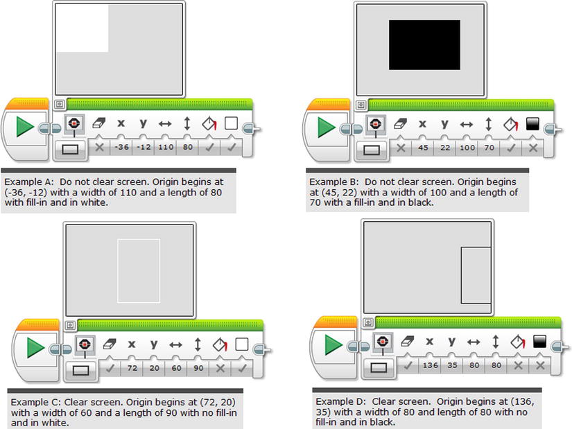
Figure 4-6. Some examples of rectangles on the display
Like the samples with the circles, you can have the rectangles or squares off the edge, and they will show.
Point
In this particular mode, it only puts a single point on the screen. You can adjust its X and Y. I didn’t include any examples as it is very difficult to see. Trust me, it works.
As I promised earlier, I wanted to give a demonstration of how to place multiple shapes on the display, so here is an example in Figure 4-7.

Figure 4-7. How to do multiple shapes on the EV3 display
Image
This allows for any kind of image, and the EV3 brick comes with several built in. All that is required is to click on the upper-right corner and click on the file folder marked LEGO Image Files. Any time you use any image for the LEGO Image Files, it will automatically show up in the Project Images file. See the examples in Figure 4-8.
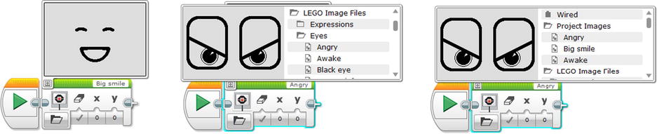
Figure 4-8. Examples of Images available on the Display programming block, and their files. Images are the creation of the LEGO Group
The following are the types of images that the EV3 Brick has:
- Expressions. These are essentially the emoticons of the EV3 Brick display, and they range from facial expressions to various hearts or other graphics that convey a feeling.
- Eyes. All of the eyes in this particular category are two rectangles with curved edges. Each of them can convey a different feeling, and sometimes the pupils can turn into interesting shapes. It is good for situations where the EV3 Brick becomes like a head.
- Information. I highly recommend using these symbols to display any kind of instruction to the user. For example, there is a stop display graphic that looks like a stop sign, as well as a question mark, thumbs up/thumbs down, etc.
- LEGO. This folder contains many Lego logos, as well as pictures of the EV3 sensors, and so on.
- Objects. As the name implies, there are a lot of objects in this folder that are difficult to classify, but they convey associations like night, snow, pirate skull and crossbones, or other objects.
- Progress. You know how your computer has a progress bar to show that some new program is loading? These images can also show progress and they include a bar, dial, hourglass, timer, and water level.
- System. This is similar to the Progress category, as it has graphics of indicators showing the status on the EV3 Brick.
Reset Screen
This is a simple function to wipe the slate clean, as it returns the EV3 Brick display to the normal screen of information on display when a program is running. You may need to do it when you need to switch from one display graphic to another.
You have the option for creating your own image. All you need to do is go to the Tools on the Main menu and click on “Image Editor”. There you will see a program similar to a paint or graphics program, as in Figure 4-9.
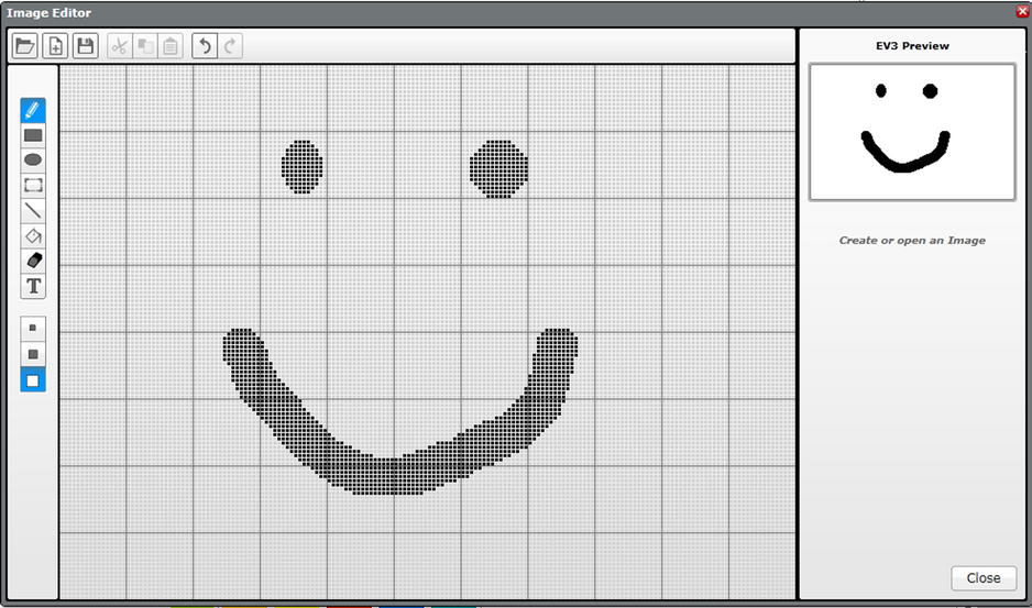
Figure 4-9. The Image Editor
You can see the horizontal menu bar on the top, and it gives you a lot of options, including:
- Open: It is possible to go into an image file and open it in this particular format. I will explain how to upload a photo onto the display later in this chapter.
- New: Clears the screen so a new image can be made. Whatever you have been drawing on the Image Editor there is not automatically saved.
- Save: You will find that this will open up a window that says “Name for Image in project”. This allows you to type in a name for your program, which you can open on the Project Images file folder on the Display programming block in Image mode.
- Cut: An option for the Select tool which I will explain when I get to the vertical menu bar. This removes a selected area so it can be pasted elsewhere.
- Copy: Another option for the Select tool, but this one does not remove the area selected. It does give you the option of pasting it.
- Paste: What you can do with a selected area after it is cut or copied.
- Undo: A way to remove an action that was just complete. I have no idea how many levels of undo there are, but I used it with 16 examples before I realized that was all that I needed.
- Redo: A way to cancel your undo.
As for the vertical bar, this is where you can select drawing tools, such as:
- Pencil: This allows you to draw whatever line or shape that you wish using your mouse or other tracking controller.
- Rectangle: Allows you to make rectangles or squares.
- Ellipse: Allows you to make ellipses or circles.
- Select: Allows you to select a rectangle or square-shaped area that you can move as well as Cut, Copy, or Paste.
- Line: Allows for making line segments.
- Fill: Allows you to fill in any shape that you have, provided it is a closed off area.
- Erase: Allows you to remove any graphics with the same type of controls as the Pencil.
- Text: Allows you to type out text in two different text styles.
- Small, Medium, and Large Pencil: This is a separate menu bar below the drawing tools bar, and it will control the size of the pencil. In addition to the Pencil, it works on the Circle, Rectangle, Line, and Eraser functions as well.
As I have stated before, the Image Editor looks like any particular paint program. I have also stated that it is possible for you to upload an image file and make it so it can be put on the EV3 Brick display. For example, I was able to load a picture of my son that I took at Arches State Park that you can see in Figure 4-10.
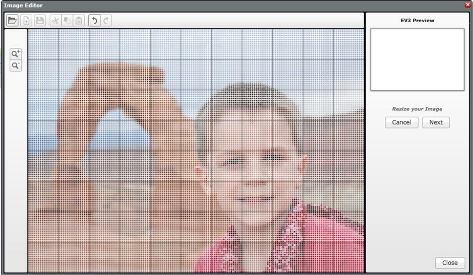
Figure 4-10. The Image Editor allows you to load pictures that you have on your computer or mobile device
You can see the magnifying buttons on the left side, which allow you to focus on the area that you want to focus on. The picture that you see here was originally taken in portrait mode, but I focused on the area that I thought was most interesting. I then hit the “Next” button on the right, and I got what you see in Figure 4-11.

Figure 4-11. A “translation” of a former image file into the LEGO MINDSTORMS display
Once I hit the “Save” button, I have a permanent image, which I titled “Arch and Son”. As you can see in Figure 4-12, the project is saved in the Project Images folder, and easily accessible.
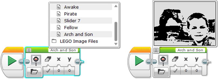
Figure 4-12. Accessing a file from the Image Editor program
As you can see, the Display programming block is a very versatile tool. Before I go any further, I want to explain that the programs above will require more if you want the images to stay on screen. For example, you can use the Wait programming block in Time mode if you want the image to stay on screen for a few seconds, and an Infinite Loop can keep it on indefinitely. I have some examples on the programs below with the data operations programming blocks.
Now that I showed you how to display visuals, it only stands to reason that I introduce sound. This block is designed solely to make some noise, whether it be a note, frequency, pre-programmed, or even user-created. It has four functions: Stop, Play File, Play Tone, and Play Note.
Stop
Stop is designed to simply cease all sound. It is good for situations when sound needs to stop; it is very similar to the Reset Screen that I mentioned when I was discussing the Display programming block.
Play Files
Play Files is designed to play a particular audio file. You can select an audio file from many categories. In case you are wondering, you can also use your own sound, provided it is only about ten seconds. I will explain how to make your own audio file later, but for the ones that are already programmed on the EV3 Brick, they are easy to access. All that is required is to click on the top-right corner and access the files, as seen in Figure 4-13.
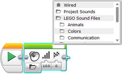
Figure 4-13. Accessing the audio files for the Sound programming block
I highly recommend playing with all the sound files, as they might add some interesting audio treats to your program. The Sound files are in several categories, including:
- Animals: The sound that a particular animal makes.
- Colors: A voice that states the color.
- Communication: Another voice that states some expression, saying things like “Fantastic” and “Good Job” in a very text-to-speech sounding robot voice.
- Expressions: Cute sounds that might be heard as filler for a radio morning show.
- Information: Any sound that communicates direction or action.
- Mechanical: Sounds that indicates that technological things are happening.
- Movements: More indicators of actions, specifically robot or motor oriented.
- Numbers: An audio recording speaking a number from zero to nine.
- System: An audio sound to confirm that some mechanical system is operational.
You will notice that one of the parameter controls are for the volume, which can range from 0 to 100.
There are also three methods of Play Type to program here in the parameters.
- Play to Completion plays the sound effect once, and then the program waits for the specific sound to finish before continuing.
- Play Once plays the sound effect once, and then the program immediately continues.
- Repeat plays the sound effect multiple times, looping ad infinitum.
The Play Tone measures a note by Hertz or its note value. You can see a good example of it working in Figure 4-14.

Figure 4-14. An example of the Play Tones
You will notice that you can enter the frequency manually by simply typing it in. You can also enter the amount of seconds that you want the tone to play. The Volume and Play Type is also here for you to control as well.
Play Note
As for the Play Note, this will set up a note to play, like a piano keyboard. You can see an example of it in Figure 4-15.

Figure 4-15. An example of the Play Note function, with a keyboard to select a note
Make your own Sound
It is possible to use the LEGO MINDSTORMS programming software to create your own kind of sound. All that is required is to go to the top of the menu bar and select Tools and Sound Editor. You will then see a small window that looks like Figure 4-16.
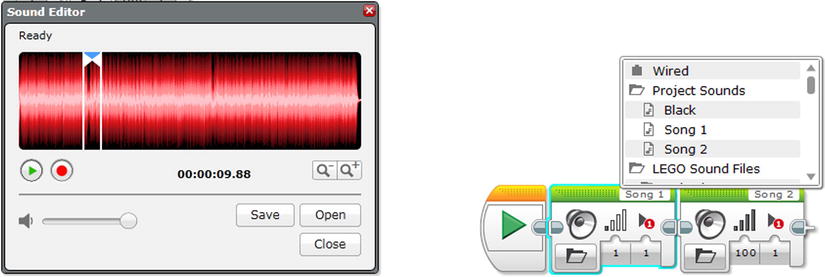
Figure 4-16. The Sound Editor on the MINDSTORMS Software on the left, and the Project Sounds programming blocks on the right
The Sound Editor works a lot like a standard voice recording software program. You essentially hit the big red button to record your voice or anything else, and then you can save it after you are done (see Figure 4-16, left). Keep in mind that the maximum length of a sound is about 10 seconds, so nothing too long can be saved. Accessing the Sound files is as easy as clicking in the upper-right corner and selecting the one in the Project Sounds folder.
In case you wanted to know whether or not you can put your favorite MP3s on your EV3 brick, I will have to say that the answer is a sad no. As I have stated before, the maximum length of a recorded sound is about 10 seconds, which is not the length of a song. You can upload an audio file, like a song, and you can select a section of a song, and then save it. These files can be saved, and they can be retrieved on the Project Sounds on the upper-right corner. It is possible to save your entire song in 10-second sections, then string them together on different recording blocks (see Figure 4-16, right).
Brick Status Light Programming Block
It is also possible to change the color of the status light on the EV3 Brick. It is pretty simple to set up, as you can see in the following examples in Figure 4-17.

Figure 4-17. Three examples of changing the brick status light (note the change in number as well as color)
I highly recommend using the Brick Status as an indicator. For example, you might want to create a program where the light is green when something is a normal condition, but red when it is not.
The Brick Status Light is the last of the green programming blocks, and now I want to spend some time talking about the red programming blocks, which are for data operations. As I stated in the introduction, the data operations blocks are used to calculate internal operations within the EV3 Brick. Oftentimes, you won’t be able to see what is going on, any more than you can read someone’s thoughts. However, you can connect the outputs of the data operation blocks to the motors as well as the display, sound, and Brick Status Lights. I have several examples below of how these can be used.
The Data Operations Programming Blocks
You are going to find the data operations programming blocks to be very helpful, as numerical values will be used in your programs a lot. Much of what you will read in this section might remind you of middle school or high school level mathematics class, and you will find that the EV3 is set up to do very high math.
Variable
If you know anything about algebra, then you know you are usually solving for x (and sometimes y). In an algebraic textbook, the variable is a container that contains an unknown quantity which you try to determine; in the case of the Variable programming block you can create your own value for your variable, and even change the value later in the program.
You will see that the Variable is a briefcase, which implies that it is a value that is closed up, until you open it. You will note its two main modes of Read and Write, with Read symbolized by a book and Write being a pencil. The Write mode is where you establish the variable name and value like writing something in a book, while Read mode is where you use that value, like reading some piece of information from a book.
The name of the variable is established by simply clicking on the upper-right corner and entering in a name, which can be pretty much anything depending on the values you are working with. You will note that Read and Write come in the form of values like Text, Numeric, Logic, Numeric Array, and Logic Array.
You can then go to the lower-right corner of the Variable block in Write mode and enter the value. After you have created a Variable, it will be saved for easy access later. So the next time you put a Variable programming block in your program, you can click on it and access the Variable by name.
Text
As we discussed earlier with the Display programming block, a text program uses words that you enter in. You can see in Figure 4-18 that this new variable is named “Test Text”, and the value is a very simple abc. You can see by the single LEGO brick on the Display Programming Block that it is in Micro mode, which means it will accept input that is wired to it.
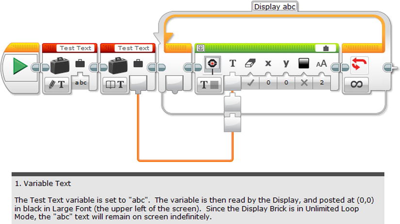
Figure 4-18. An Example of using Variable for the Text
It’s pretty simple to wire the value of Test Text into the Display programming block. You will notice that the Display block is in a loop, so the value of Test Text will display indefinitely. I recommend running this program yourself, and even changing the value of the Test Text to something else. I am not certain how many characters you can have in your text, but the display size is limited if you want to try to display entire paragraphs without using multiple Display programming blocks.
Numeric
Numeric is for reading and writing variables that are numbers. You can see the example of its writing and reading in Figure 4-19.

Figure 4-19. An example of the Variable Numeric
You will notice that the number is plugged into the amount of rotations for the Large Motor’s On For Rotations parameter. It is also plugged into the Loop programming block, and it is on the Count Setting’s number of time. This means that the action on Port D will play three times for a total of nine rotations.
Logic
You may recall lessons in your mathematics class that dealt with logic, and much of it consisted of establishing values as “true” or “false” and working within those conditions. In the case of the logic Variable, you are essentially establishing a case of True or False, and then using it, like in Figure 4-20.
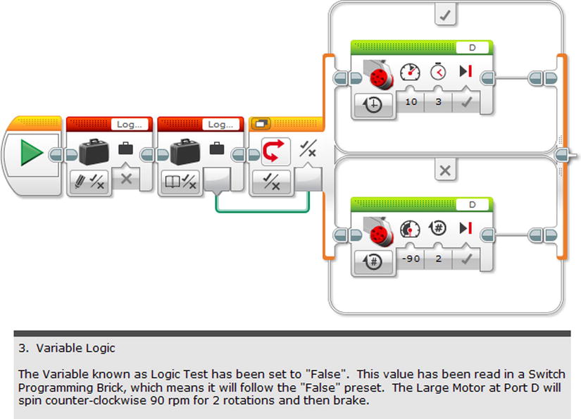
Figure 4-20. An example of Variable Logic
You will notice that the name of the Variable is “Log…”. It is actually “Logic Test”, but the space in the upper-right corner abbreviates it to make it fit. You can see that Logic Test has been set to a value of “False”, and this value is plugged into a Logic Loop. The Logic Loop was something that I only touched upon in the last chapter, but it is essentially a way of telling the program: “If the value is true, then do this. But if the value is false, then do that.” In the case of Figure 4-20, the value is set to false (the cross in the variable block), so it will spin a faster –90 rpm for 2 rotations instead of the slower 10 rpm for 3 seconds (i.e., it uses the block in the cross section, rather than the block in the tick section).
Numeric Array and Logic Array
You have probably noticed that Array has its own category on the data operations programming blocks. If you aren’t familiar with an array, think of it as a group of something. In the case of Variable, it comes in two forms, Numeric and Logic. The Numeric Array is essentially a group of numbers, while the Logic Array is a group of True/False statements.
To write an array, all you have to do is click on the lower-right corner of the block and then enter in your values. You can see the Numeric example in Figure 4-21 has three values of 1, 4, and 5. Individual values can be deleted by clicking on the “X” beside the individual value, while more values can be added by clicking on the “+” button.
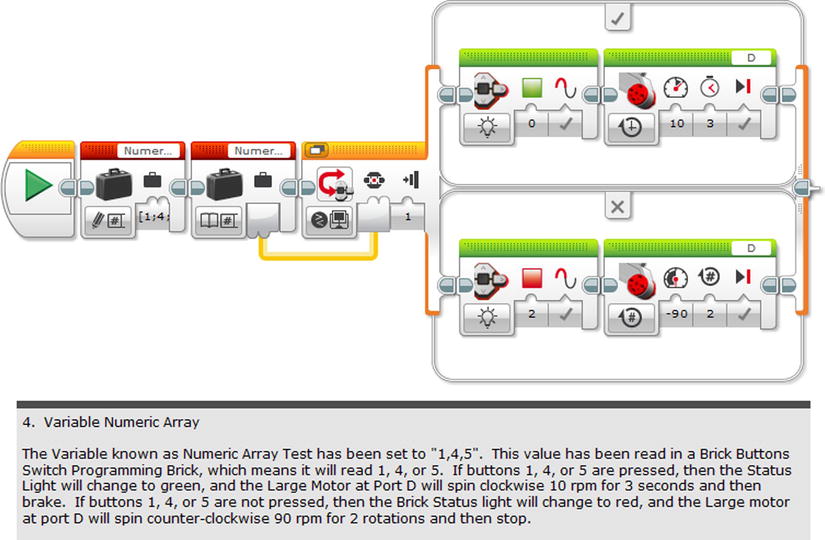
Figure 4-21. An Example of a Variable Numeric Array
In Figure 4-21, the values of 1, 4, and 5 are wired into a Brick Button's Switch programming block, and correspond to the numeric values of the Brick Buttons. This means if the left button, top button, or bottom button are pressed, then the Large Motor at Port D will spin clockwise 10 rpm for 3 seconds. If these buttons are not pressed, it will go into a default setting, spinning counter-clockwise at 90 rpm for 2 rotations. Note that the program is configured so the Brick Status Light will glow green with the proper button is pressed and red when it is not.
I will explain more about Logic Arrays when we get to the Arrays section, but right now, I want to focus on the Constant.
Constant
If you can remember using variables in your mathematics class, then you probably remember constants. Unlike Variables, Constants are values that are known and never change. You will notice that the icon of the Constant is a locked briefcase, which symbolizes how unchanging it is. Once you have typed the value of the Constant in the upper-right corner, it is established. You will notice that the value can only be Read, and it is in the same forms as the Variable with Text, Numeric, Logic, Numeric Array, and Logic Array.
Constants are helpful when you have a program where the same number is used over and over again, such as the rpm. It is easy to simply establish this constant at the beginning, and then wire it in all the places where it will be used. If you want to change this constant, it is simple and will affect all the blocks that it is wired to. There are several examples in Figure 4-22.
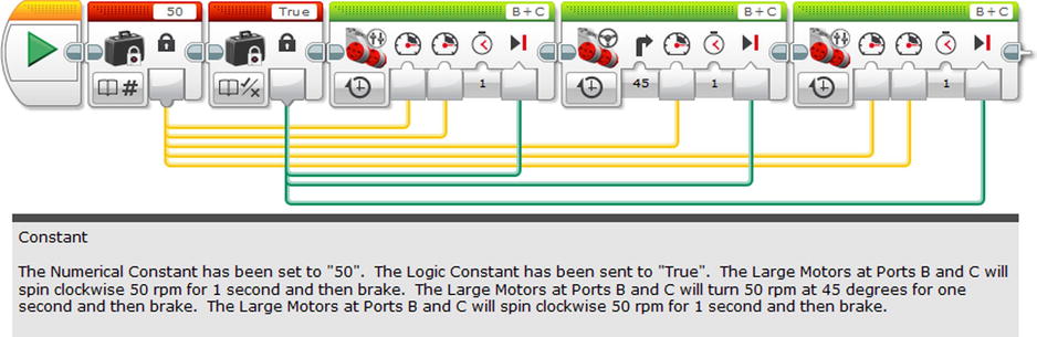
Figure 4-22. Example of a Constant in a Program
In Figure 4-22, you will note that a Constant Numeric value of 50 is plugged into the rpm of the three green programming blocks. The value of True is a Constant, and plugged into the blocks as well. If you wanted to change the rpm, all you would need to do is change the value of the constant in one spot instead of many. The same goes for the braking constants. Keep in mind it is not possible to change some of the three cases, unless you add more constants or enter in the parameters manually.
As I explained in the Variables section, it is helpful to create an Array if you want to use multiple numeric values, or multiple true/false values. The Array is very helpful, and it comes in four modes: Array Append, Read at Index, Write at Index, and Length.
Array Append
This first Append mode will add a value onto your established array. So if you have a group of four values in your array, you will have five after you run it through this programming block. The value is established as a parameter, as seen in Figure 4-23.
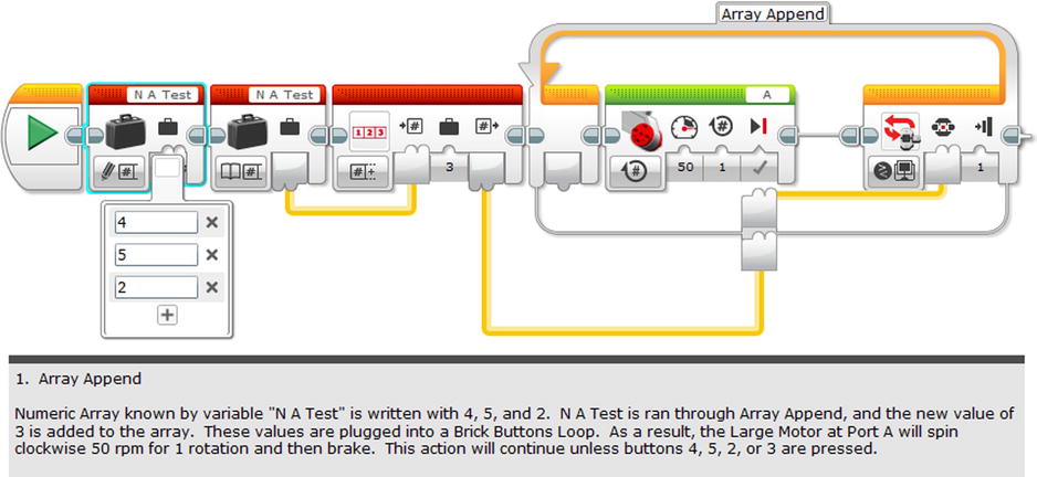
Figure 4-23. An example of Array Append
You can see that the Variable of “N A Test” is initialized as a Numeric Array of 4, 5, and 2. Once I put it through the Array Append, a new value of 3 is now a part of this array, making it 4, 5, 2, and 3. Since the Brick Buttons Loop is set to spin a Motor for one rotation, it will only stop if the numeric value of certain brick buttons (4, 5, 2, and 3) are pressed.
With Read at Index, it is possible to create an array, and then access one of the values at a specific point in the array. You can see an example of it in Figure 4-24 with a newly created Logic Array.
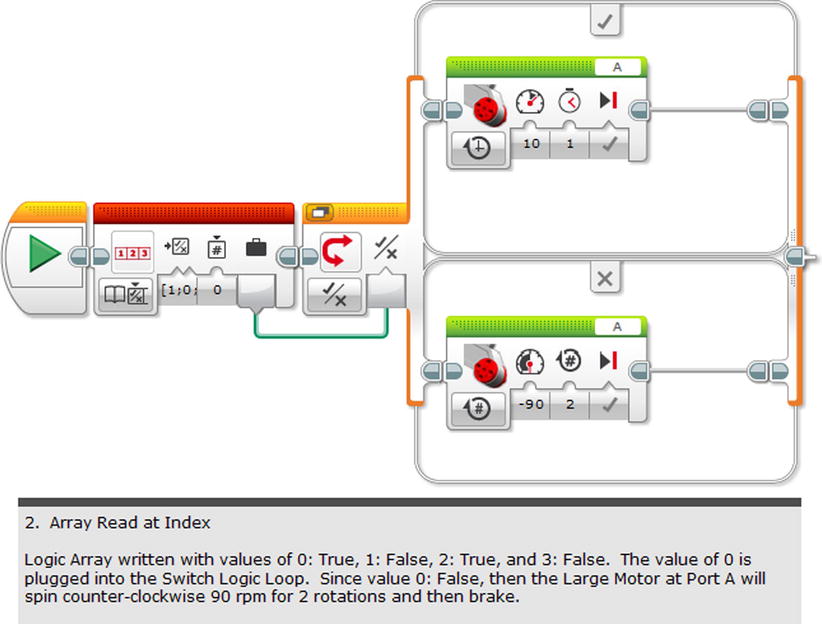
Figure 4-24. An example of an Array Read at Index
You will notice the Logic Array values start at 0 and end at 3. That is slightly confusing, but this is how the Array programming block organizes your information. You can see that the parameter is set to “0”, so it takes the first input of the array, which is “true” and plugs it directly into the Switch Logic. Note this always causes the same action, but switching it to a parameter of “False” will cause something different.
Write at Index also allows you to create arrays, but you can also alter one of the values at the address or index. You can see in the example of Figure 4-25 how the number for parameter 3 was changed from 4 to 5.
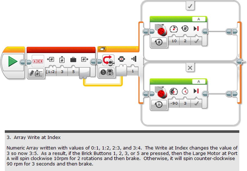
Figure 4-25. An example of Array Write at Index
You can see that the numerical values for the Brick Buttons have now been changed from 1, 2, 3, and 4 to 1, 2, 3 and 5. The Write at Index is perfect for situations in which you only want one value to change and not the entire array.
Array Length
The purpose of Array Length is to take the number of cases in an array and export the number. There is an example in Figure 4-26.
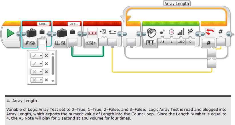
Figure 4-26. An example of Array Length
As you can see, the Logic Array Test has four distinct cases, and therefore exporting the number of them via wire into a Count Loop allows the A5 note to play four distinct times.
Logic
Logic is all about establishing if a first value is true or false, a second value is true or false, and what the result will be when you apply a logic operator to the values. You have four choices of logic operator, and this includes the “Not” which will reverse the value from true to false, or vice versa:
- a AND b
- a OR b
- a XOR b
- Not a
You can then select true or false values for a and b, and then use the result of the logic operation to determine if an event happens or doesn’t happen. I have examples of each, starting with a simple example of AND.
Logic AND
For AND, it is about two conditions that must be true in order to make the AND statement true. The easiest way to describe this is using the Touch Sensors, which can either be True (pressed) or False (unpressed). Figure 4-27 is an example of an AND statement where both must be pressed to create the “True” condition.

Figure 4-27. The use of Logic AND in an EV3 Program
Figure 4-27 has two Touch Sensors rigged at Ports 1 and 4, and both of them must be pressed to pass the Logic Switch. You can rig up this program pretty easily, and note what happens when one Touch Sensor is pressed but not the other, or no Touch Sensors are pressed. Keep in mind that the timing is important for this, as the programming will dictate going from one block to the other. In other words, it is important to press both Touch Sensors at the very beginning to produce the positive result. Timing is also important for the OR, XOR, and Not functions.
Logic OR
If we were to change the program in Figure 4-27 to an OR statement, then it would only require one of the switches to be pressed to create a True statement. In short, we are creating a condition where only one element has to be true to make the entire situation true. Here is another example in Figure 4-28.
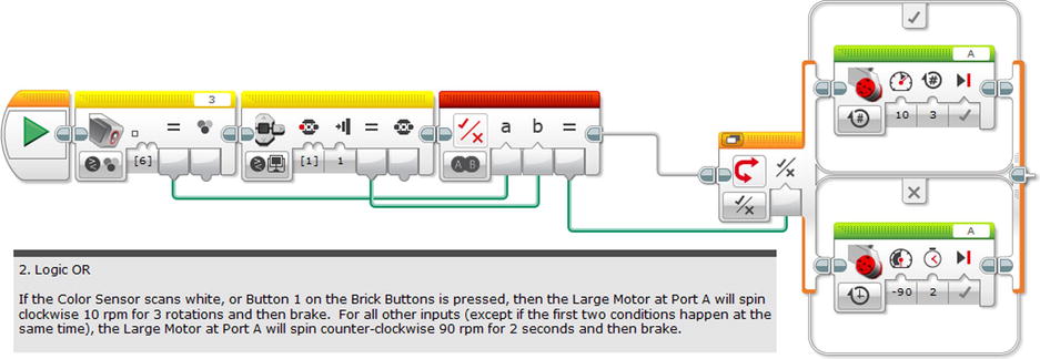
Figure 4-28. An example of Logic OR
You can see that the first condition is the Color Scanner must scan White, also known by its numeric value of 6. The second condition is that button 2 must be pressed. If you tried this program yourself, then you will find it only takes one of these conditions to get the Large Motor at Port A to spin slowly. The value of True will also occur if both of these conditions are present.
The XOR stands for Exclusive Or, which will only read True provided both conditions are the opposite of each other. I used the Brick Buttons in Figure 4-29 to illustrate this.

Figure 4-29. An example of Logic XOR
For these two conditions, all it takes is for just one to be pressed to be True while the other is not pressed. In other words, the inputs have to be the opposite of each other. Try this out for yourself.
Not A
The condition of Not Asimply takes what would have been a True output and shifts it immediately to a False one, and shifts a False output to a True one. I went ahead and added a Not A to Figure 4-30, and put it in the program below.
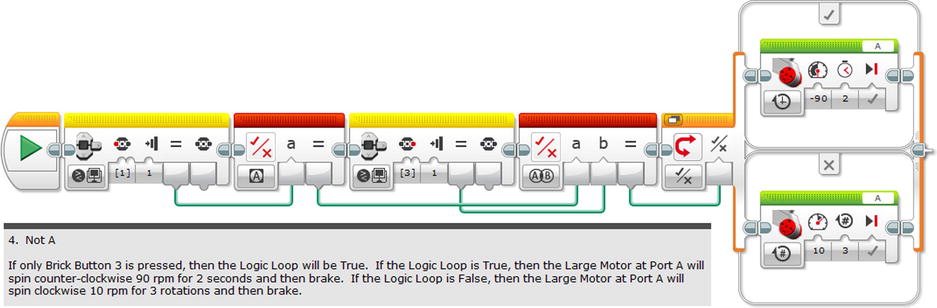
Figure 4-30. An example of Not A
If you run the program, you will find that it only reads True if Brick Button 3 and only this button is pressed. This is because this represents a positive input, while not pressing 1 produces the True result.
Math
In addition to the logic operations you might want to do some math problems while you program. You may need to use mathematics in your programs, and this will help you for when you want to use addition, subtraction, multiplication, or division of two numeric values. You can see a complex example in Figure 4-31, and I used a Count Loop to create a problem that will display the answer in text form.
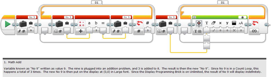
Figure 4-31. An example of the Math programming block, with an emphasis on Addition
If you tried this program, then you should see “18” on the display, because 3 was added to the original 9 three times, so 9+3=12, 12+3=15, and 15+3=18. If you didn’t, check your program or your arithmetic. You might want to tinker around with the formula and see what results you can get. The EV3 Brick is as good as a calculator.
The Math programming block is also good for when you want to find the absolute value or square root of one numeric value. You can also find an exponent if you have a number and the exponent. You can see this example in Figure 4-32 which demonstrates the application of the Pythagorean Theorem on a triangle whose opposite and adjacent sides are 6 and 8.
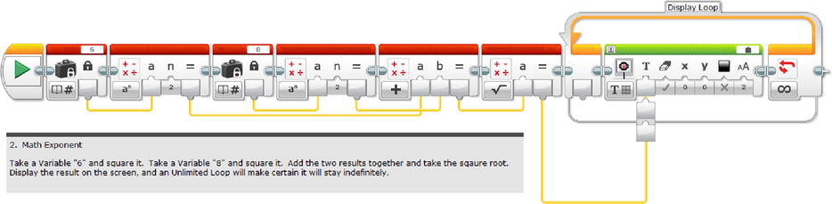
Figure 4-32. An example of the Math programming block with exponents and square roots
This time, I won’t bother spoiling the answer for you with this one. You probably already know it if you took trigonometry and studied basic Pythagorean triplicates.
You can even do real complex math with four numeric units, with a, b, c, and d. With the Advanced function, you can do a lot of other complex equations like sine, cosine, and tangent, and a lot more. You can see some examples in Figure 4-33.

Figure 4-33. Examples of more advanced math functions on the Math programming block
Round
Occasionally, while you are doing math, you might end up with a repeating decimal or irrational number that you want to round off. The Round program has four options:
- To Nearest. This will round your decimal to the nearest whole number.
- Round Up. This will round up to your decimal to the nearest whole number, whatever it may be.
- Round Down. This will round down your decimal to the nearest whole number, whatever it may be.
- Truncate: Here is where you can set the parameters for your number in decimal places.
I have included examples in Figure 4-34 so you can see the varied results, and you will see different outputs on the display all with the same Constant of 43.5687.

Figure 4-34. Some examples of how to use the Round programming block
Compare
Compare allows you to compare two numeric values with Equal To, Not Equal To, Greater Than, Greater Than or Equal To, Less Than, or Less Than or Equal To. Using the Math programming block and a Switch, you can set it up to have different reactions depending on the result. There is an example in Figure 4-35.
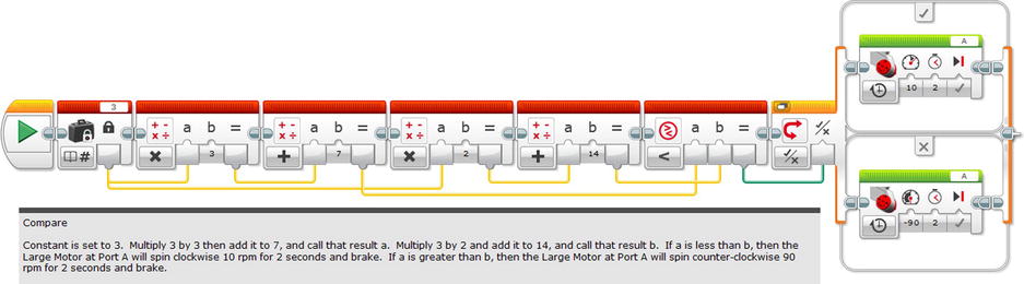
Figure 4-35. An example of the Compare programming block
You can see that the set-up is for a certain equation, and whatever is the lesser amount will trigger the positive action. You can easily change the constant to something else if you want to see a different result, and change the inequality sign as well.
Range
Range is helpful for situations where you want to establish a lowest and highest value for something. For example, you can call a vehicle to come only within a certain range of something and then stop. You can command it to stay inside or outside of its range which can be established between any two numeric values. There is an example in Figure 4-36 of a program designed to do just that.
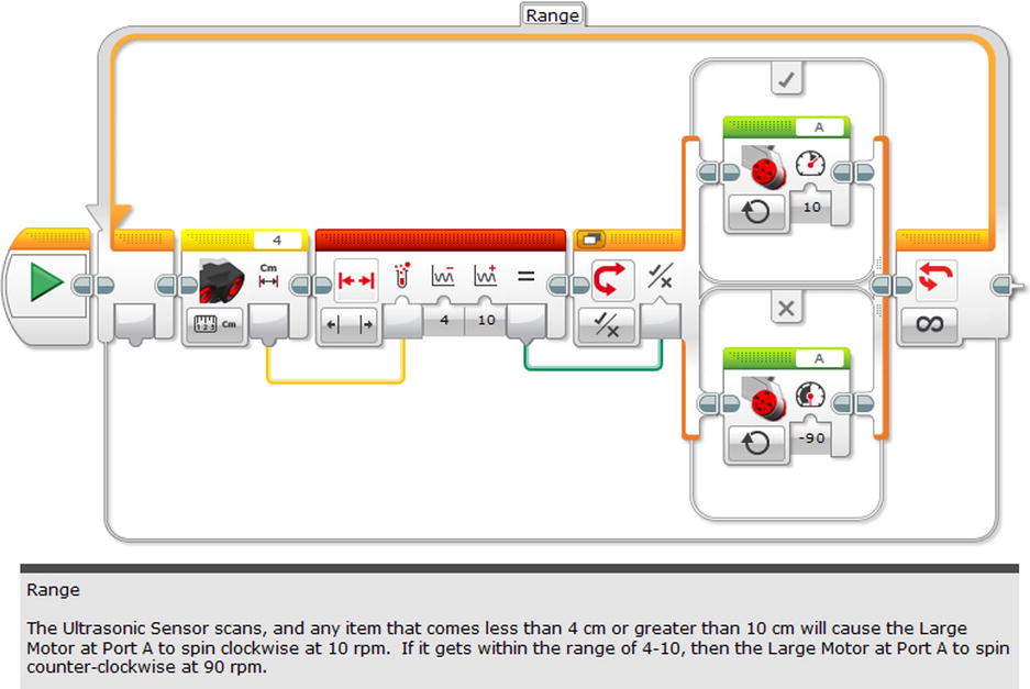
Figure 4-36. An example of using the Range programming block
In the example in Figure 4-35, it is programmed in Outside mode to produce its results. The same results can be done with the Inside mode, although the parameters and cases would need to change.
Text
Text is about taking up to three values of text and merging them together. This is incredibly helpful for situations when you want the display to show you values of something. For example, if you want to hook up the Ultrasonic Sensor so it can measure things a distance away, this is what you use in Figure 4-37.
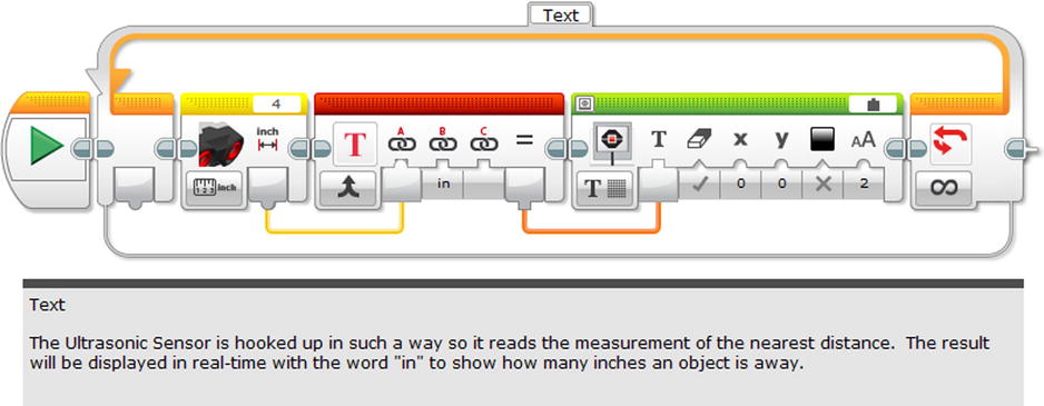
Figure 4-37. An example using Text
If you run the program, you can put your hand right in front of the Ultrasonic Sensor and watch as the display shows the distance between your hand and the sensor in real time.
Random
Recall how you set up values with the Range: Random is all about letting the EV3 Brick come up with a value that it selects on a whim, with no bias. It can be used for Logic, such as a yes or no percentage from 0 to 100. For instance, an input of 20 would create a situation that has an output of 20% True and an 80% False output. It can also be used as a random number generator as seen in Figure 4-38.

Figure 4-38. A demonstration of the Random programming block
As you can see from Figure 4-38, the Random Number Generator will discover a number in between –25 and 75, and then plug it into the speed for the Large Motors at Ports B and C. Will it be fast? Will it be slow? It is truly a roll of the dice.
With the right application of Random, you can create a vehicle that will go all over the floor in completely random directions and speeds.
Summary
In creating programs for the LEGO MINDSTORMS EV3, it is helpful to know how to insert a graphic for the display, a sound, or even change the Brick Status light. Fortunately, it comes with programming blocks that will help with that.
For example, the Display programming block is set up for text, lines, and point. It can also do shapes like circles and rectangles, and it is possible to enter in your own drawing with the included Image Editor program.
As for sound, the Play File program comes with all kinds of sounds to enter. It is possible to program it to play a Tone or a Note as well. Like the Image Editor, it is possible to record one’s own sound with the Sound Editor program, included on the EV3 Software program.
The Brick Display Light can also be constructed to turn whatever color that you wish as well with its personal programming block.
In addition to the sight and sound, LEGO MINDSTORMS equips the user to manipulate data with the data programming blocks. These red blocks are very handy for setting values, not to mention all kinds of arithmetical operations.
I highly recommend playing with all of these functions. Not only will you become more adept at placing them in your programs, but it is really a lot of fun.