![]()
Special Construction Projects and Macros
Now that I covered creating a vehicle in Chapter 3 as well as advanced programming steps in Chapter 5, I imagine you want to make that vehicle do all kinds of things. This chapter discusses how to create a lot of specialized vehicles like forklifts, cranes, scissorlifts, and other types of construction equipment.
Before I begin, I want to explain that even though I will be explaining how to program these specialized features, I am not going to really explain how to build vehicles that will house these constructions. It would take me too long and too many pages of instructions to do that, so you will see things like the lifting part of a forklift, but not the wheels. As I have stated in the introductory part of my book, the purpose of this book is that you create cool LEGO MINDSTORMS creations, not imitate the models here.
I will start with one of the easiest and most necessary projects for the swivel. I use the term swivel to describe any time you want some apparatus to turn, and this can spin at 360 degrees. If you follow the instructions below, you can easily create a decent swivel. You will need the turntable piece, which is shown in the following instructions. It is possible to use a bigger turntable piece if you wish.
Project 6-1: The Swivel
I highly suggest using the Gyro Sensor to make certain it will work correctly. Please keep in mind that since you will need to connect them with connector cables, the ability to spin freely could be limited. The instructions are shown in Figures 6-1 to 6-17.
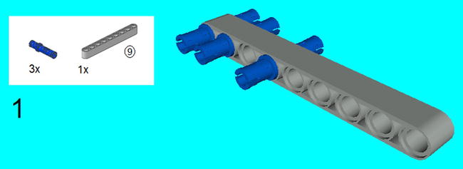
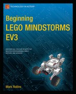
Figure 6-1. Take a 9M beam and center three 3M connector pegs in the following through-holes as shown
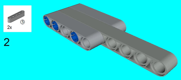

Figure 6-3. Use the friction snaps to click in two 5 × 3 beams as shown, and insert the three connector pegs
Figure 6-4. Install the 11M beam on top. Snap on two friction snaps, but only halfway on
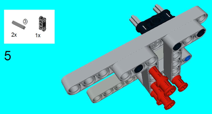
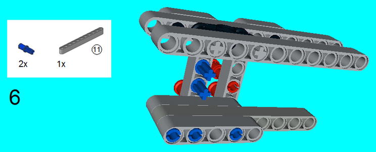
Figure 6-6. Insert another 11M beam on the other side of the double cross block, and insert the connector peg/cross axles as shown
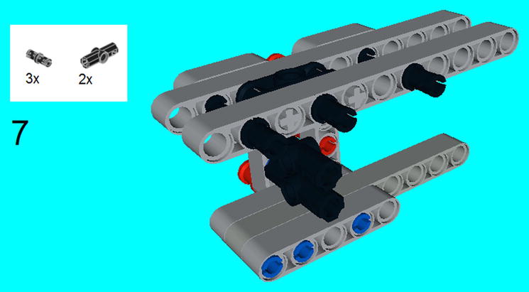
Figure 6-7. Place the two 180 degree angle elements on the connector peg/cross axles, and place the connector pegs on the 11M beam on top
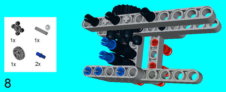
Figure 6-8. Stick a 3M axle through the angular wheel just above the 180 angle elements, then place the Z20 bevel gear on top of that. Stick on the connector peg/cross axles on the 180 degree angle elements
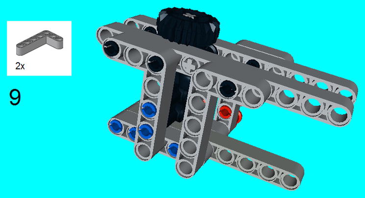
Figure 6-9. Snap on the two 5 × 3 beams on the side to hold the structure together
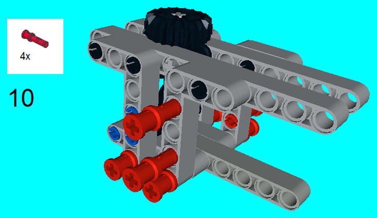
Figure 6-10. On the bottom of the structure, push in two Friction Snaps all the way through. Push the other two friction snaps halfway in

Figure 6-11. Center an angular wheel on the 3M axle, and place it in the center of the 180 degree angle element
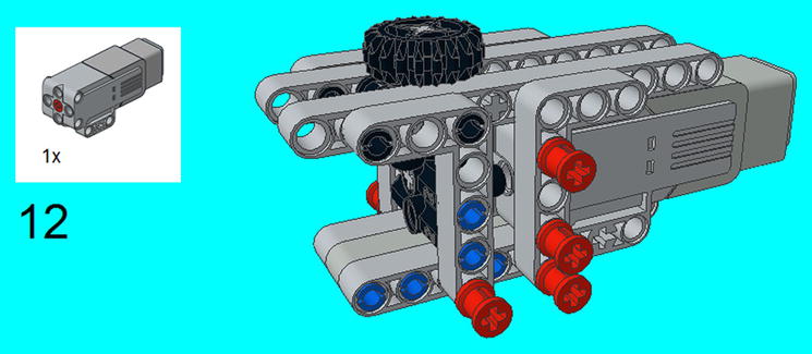
Figure 6-12. Slide the Medium Motor on the 3M axle from the last step, and secure it by pressing in the friction snaps that were halfway in steps 4 and 10
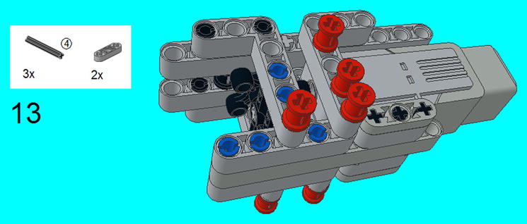
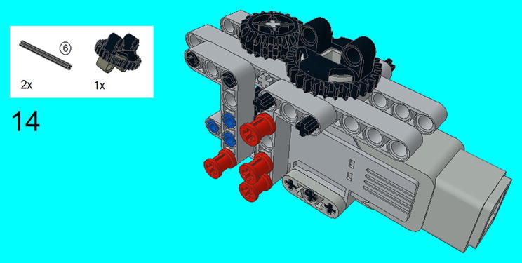
Figure 6-14. Insert the small turntable on top so it meshes with the Z20 bevel gear. Secure the turntable on the sides with two 6M axles and it will be secured in the next step

Figure 6-15. Use the two 3M levers to secure the two 6M axles from the previous step. Center the two 3M Connector Pegs on top of the small turntable
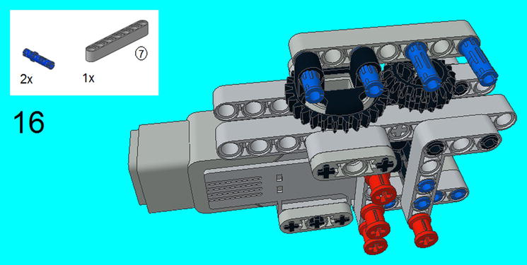

Figure 6-17. Slide the Gyro Sensor in the center of the 3M Connector Pegs, and snap on another 7M Beam on top
Programming the Swivel
LEGO MINDSTORMS has an easy to program tool to spin and stop where you want it. Using the Wait Program block with the mode of the Gyro Sensor, you can input whatever angle you want it to stop at, as seen in Figure 6-18.
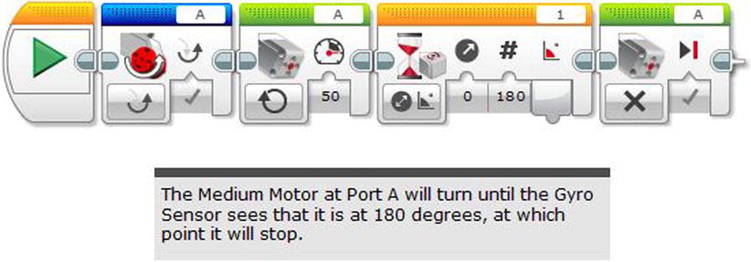
Figure 6-18. A program for spinning the Swivel program in Project 6-1 at 180 degrees, but it can be easily reprogrammed for any angle
There are instructions for some sort of lifter on the Core Set instruction booklet, but the following instructions will allow it to work like a traditional forklift. You may find it similar to the stair climber in the Expansion Set.
Project 6-2: The Forklift
Follow Figures 6-19 to 6-38 to build the forklift.
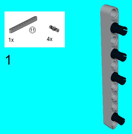
Figure 6-19. Take an 11M beam and place the four connector pegs on it as shown
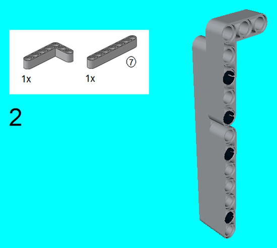
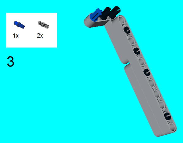
Figure 6-21. Click in the two connector pegs and connector peg/cross axle
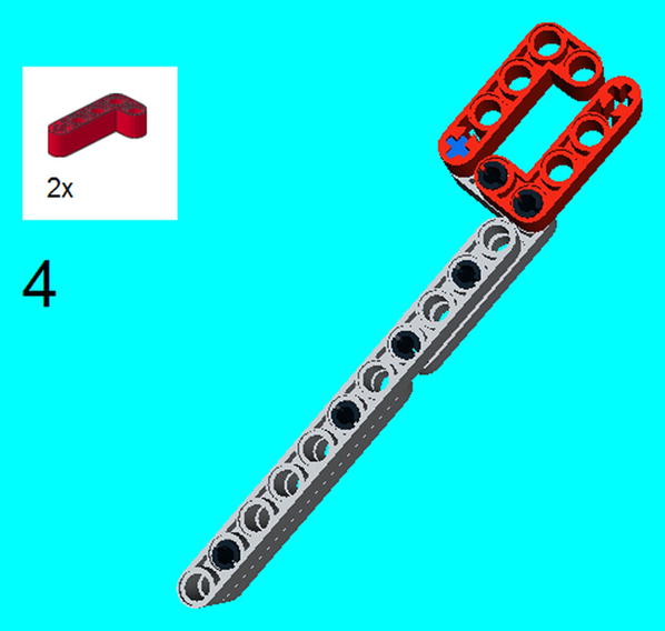
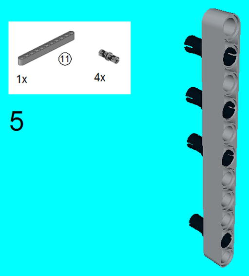
Figure 6-23. Steps 5-8 are a separate section that mirrors steps 1-4. Take an 11M beam and place the four connector pegs on it as shown

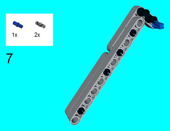
Figure 6-25. Click in the two connector pegs and connector peg/cross axle
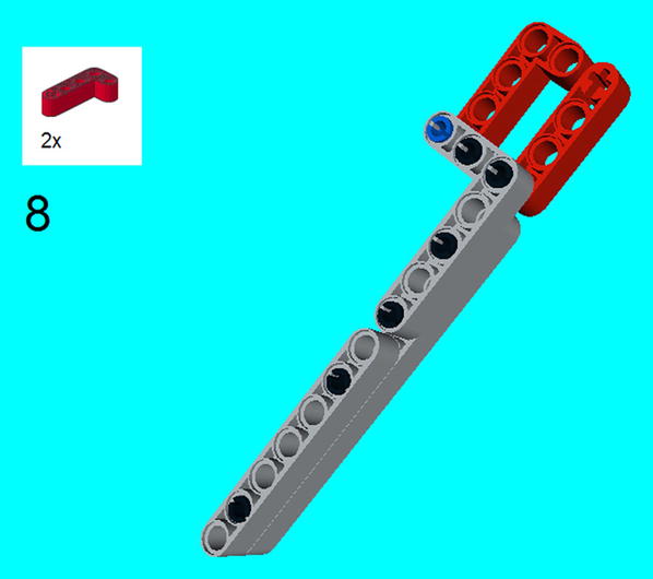
Figure 6-26. Click on the two 4 × 2 angular beams

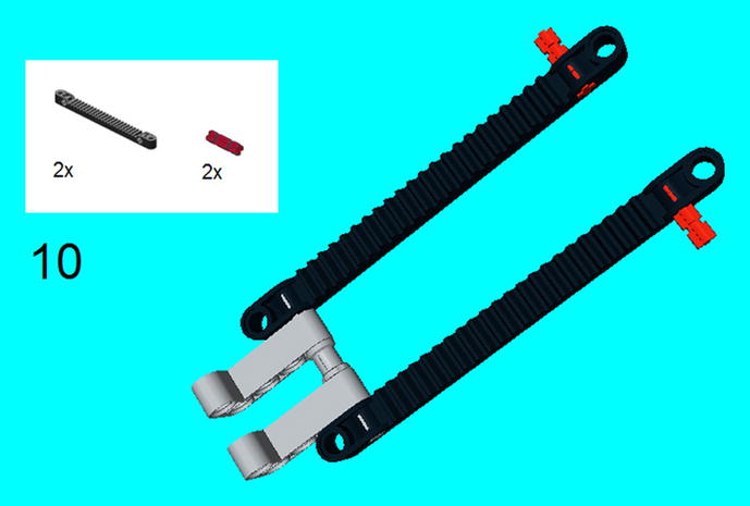
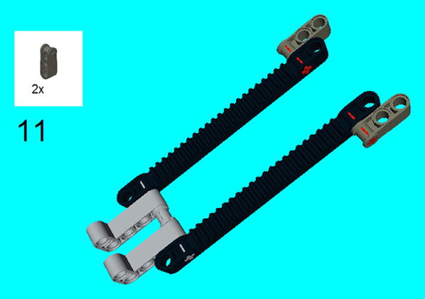

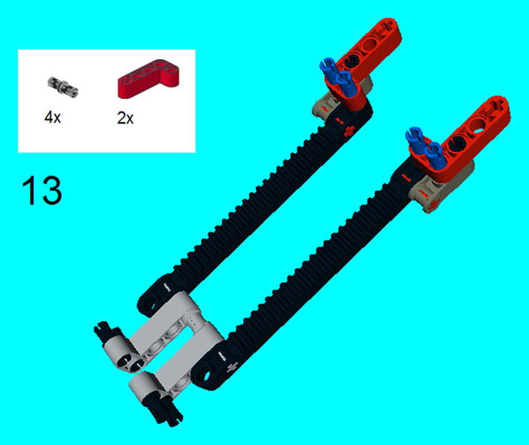
Figure 6-31. Slide on the 4 × 2 beams on top. Insert the four connector pegs on the 4 × 2 beams on the bottom
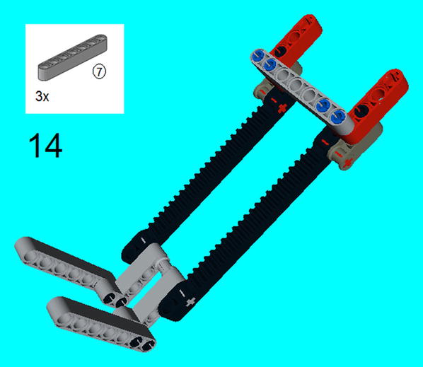
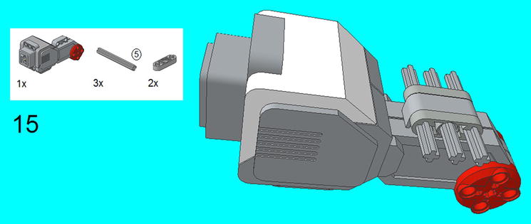
Figure 6-33. Take out a Large Motor and center three 5M axles on top. Secure them with two 3M levers

Figure 6-34. Insert the right-side section done in steps 1-4
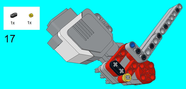

Figure 6-36. Insert the left-side section done in steps 5-8

Figure 6-37. Slide on the half-bush and 2M lever to secure the left-side section
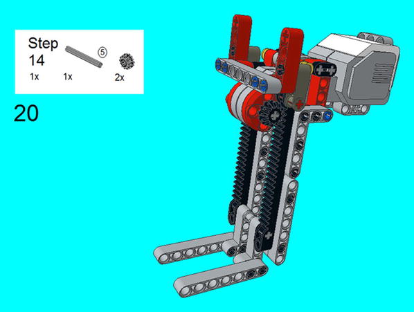
Figure 6-38. Slide in the 5M axle with the two bevel gears, and secure the center section at the top
Programming the Forklift
Since the Large Motor is attached directly to the two bevel gears, all you need to do is tell them how long to spin, and they will raise or lower the central section. I discovered that asking the EV3 Brick to spin the gears at 540 degrees or 1.5 rotations allowed the prongs to go from top to bottom, as seen in Figure 6-39. Be careful with any tampering with this formula, as you don’t want the gears to jam on the racks. This is why I recommend using the formula in Figure 6-39 with the forklift prongs all the way at the bottom, but if you want to make the forklift go halfway up, you can just program it to spin 270 degrees.

Figure 6-39. A program for operating the forklift of Project 6-2
This is a variation of a project I made in the LEGO Technic Robotics book, but it is greatly simplified with the addition of a Large Motor. If you aren’t familiar with a scissorlift, it uses a pantagraph method of taking someone or something higher up. If you are not familiar with a pantagraph, look to Figure 6-71. You might see something like it at construction sites or other places where higher levels must be reached.
Project 6-3: The Scissorlift
To build the scissorlift, follow the instructions in Figures 6-40 to 6-70.
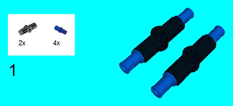
Figure 6-40. Place connector peg/cross axles on each end of the two 180-degree angle elements
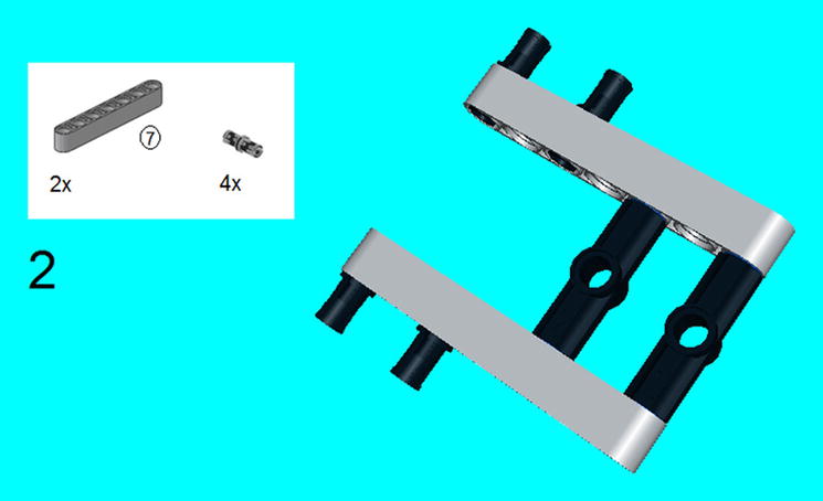
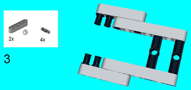
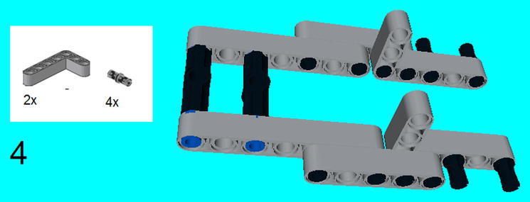
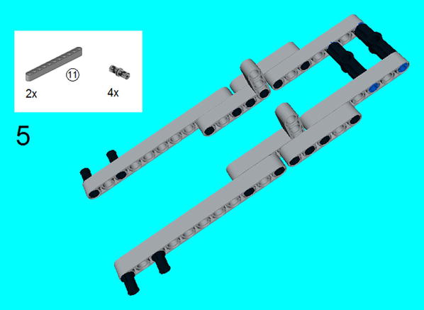

Figure 6-45. Snap on the 5 × 3 beams and connector pegs as well as the connector peg/cross axles
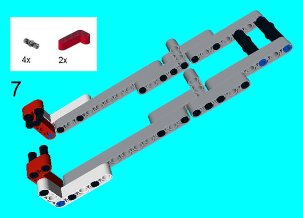
Figure 6-46. Snap on the 4 × 2 beams and the connector pegs on that

Figure 6-47. Snap on the 15M beams and the eight connector pegs as shown, with four connector pegs on the front and four in the middle
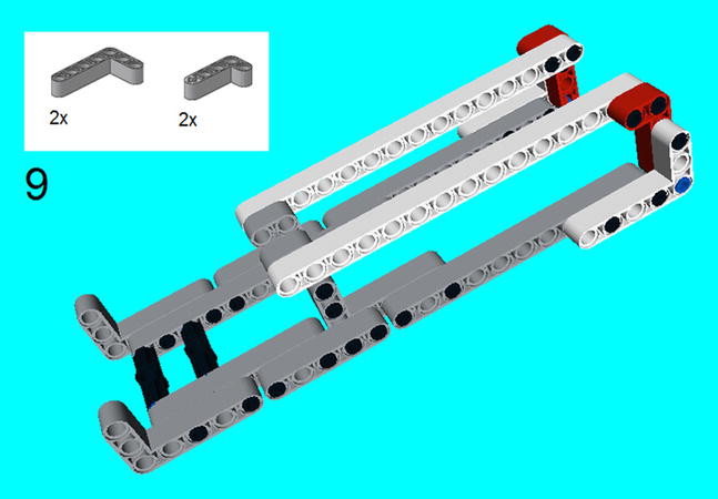
Figure 6-48. Snap on the 5 × 3 beams as well as 4 × 2 beams

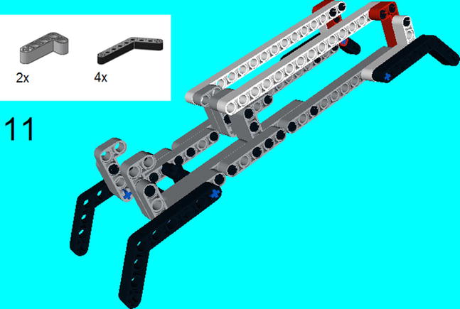
Figure 6-50. Click on the two 4 × 2 beams and the four 6 × 4 beams below
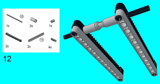
Figure 6-51. This step is separate from the rest of the construction. Attach the 13M beams on the 13M racks with the four connector pegs. Connect them together with the 12M axle with the two tubes and bush in the middle

Figure 6-52. Attach the six connector pegs on the 4 × 2 beam and 15M beams. Slide in the 3M connector pegs all the way, through the middle 4 × 2 and 15M beams. The 3M connector pegs without friction as shown
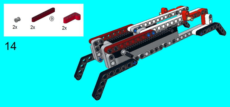
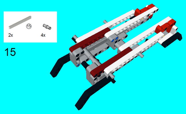
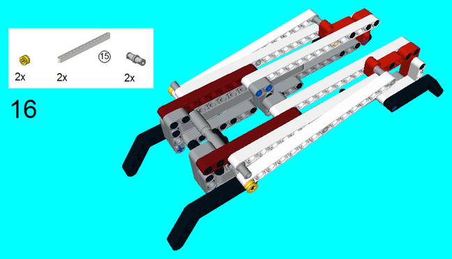
Figure 6-55. Slide on end of the 15M beam on the 12M axle, and cap it off with the half bushes. The center of the 15M beam snaps onto the connector pegs (without friction) and another connector peg (without friction) on the other end of the 15M beams
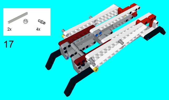
Figure 6-56. Snap on the 15M beams and connector pegs
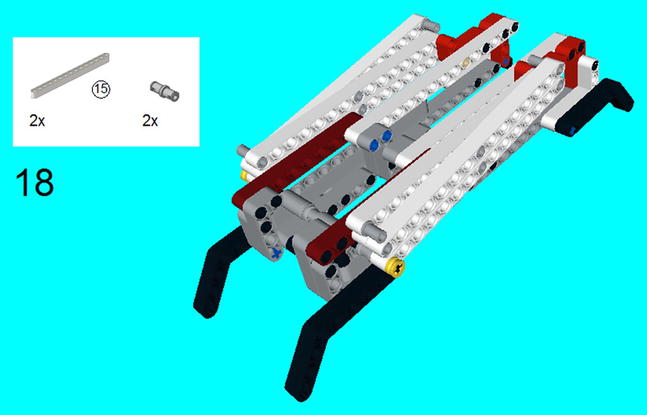

Figure 6-58. Snap on the 15M beams and connector pegs
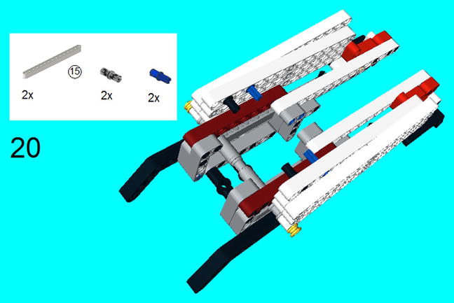
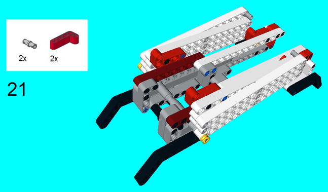
Figure 6-60. Snap on the 4 × 2 beams and connector pegs
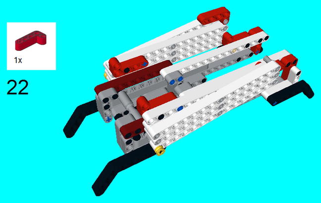
Figure 6-61. Snap on the 4 × 2 beam
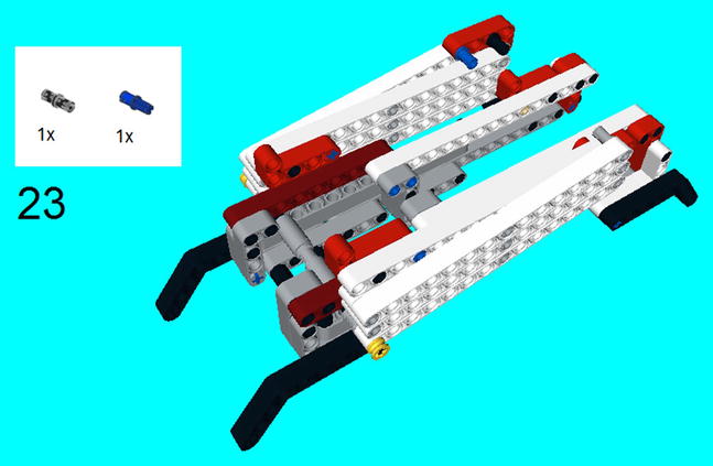
Figure 6-62. Snap on the connector peg and connector peg/cross axle
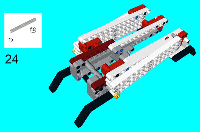
Figure 6-63. Snap on the 15M beam

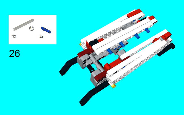
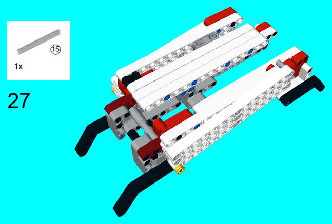
Figure 6-66. Snap on the 15M beam
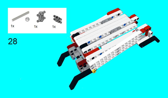
Figure 6-67. Snap on the 15M beam, modular connector peg, and 1 × 3 peg
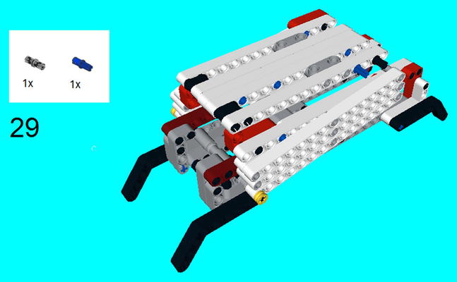
Figure 6-68. Snap on the connector peg and connector peg/cross axle
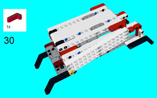
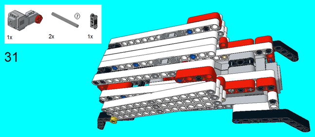
Figure 6-70. Place the Large Motor on the construction, and put the double cross block in the middle. Slide the two 7M axles in to lock it in place

Figure 6-71. I raised up the pantagraph and took a photo so you can see the step here more clearly. You need to slide the 7M axle through the Large Motor and then add the gears at each end, making certain that they mesh with the racks. Attach the connector cable and EV3 Brick, and it is ready to lift
Programming the Scissorlift
Like the forklift, the twin bevel gears are set to spin when the Large Motor turns. This causes the racks to move, and I discovered that one full rotations is all that is needed to get the scissorlift platform to rise to its highest point. Again, I warn you on your own programming endeavors, as you can jam the gears.
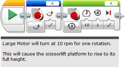
Figure 6-72. A program for the scissorlift
Make Me a Macro
If you know anything about programming, then you know the importance of macros. If you are not familiar with them, then it is simply a way that you can do several things with just the push of a button.
You will discover as you are programming on LEGO MINDSTORMS that you are often doing the same things over and over again. Instead of cutting and pasting the same code from one location to the next, I highly recommend using macros.
Macros are the last type of programming block that I want to address. All that is required is to simply create a bunch of programming blocks that you want to be a macro and then highlight all of it. Go into the Menu bar and select Tools and “My Block Builder”. Input your information in the Macro screen as seen in Figure 6-73. Note that you can add your parameter and its icons, so all you need to do is enter a few values.

Figure 6-73. The steps required to create your own individual programming block
Once you have created your macro block, it will be in the Indigo section on the programming blocks, ready to be used. For example, let’s say you built Project 6-2, the forklift, and you just want to simplify the lifting of the prongs. Figure 6-74 shows a way.
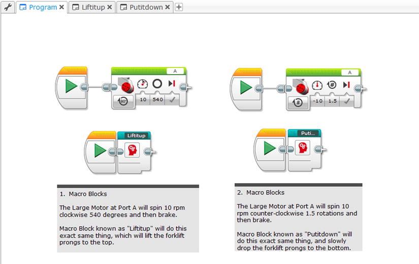
Figure 6-74. A way to use the forklift using the Macro blocks
Note that the programs of lifting the forks up and putting them down have been reduced to a single block. So if they ever need to be used again, they can be accessed down below without ever needed parameters entered in. You will notice that if you click on a Macro block, it will open up a tab that will show all the blocks within.
Now that you have created a macro, you will discover that it can be a major shortcut in your program. In fact, you can even create macros that have macros.
Summary
In addition to programming simple vehicles that can travel across flat areas, you will want to create LEGO MINDSTORMS vehicles that can do special features, like construction equipment.
This chapter details how to use the Medium and Large Motors to create such real-life examples of a swivel that can turn it 360 degrees and more, a forklift with prongs that can lift items, and a scissorlift which can rise quite high.
Programming these types of vehicles is also simple, but be careful when manipulating them as they could cause gears and motors to jam. Therefore, I recommend that you start the swivel, forklift, and scissorlift in the same place and end them in the same place each time they are used.
Once you have your construction into what you want it to be, you can start with the programming. You may discover that you will often be repeating certain actions, so it might be simpler to make a macro. Macros allow you to put a lot of code onto one block, and these macros can even contain macros themselves.