
![]()
Thinking like a LEGO MINDSTORMS Creator and the Walking Robot
As I have said before, this book is not about giving you some instructions for models, and then giving you the programs that you will need to run them. LEGO is all about creation, and I see little reason to give you things to build when the true joy of LEGO is creating a masterpiece that you can proudly say: “see that, I made that from start to finish.” And “I put my blood, sweat, and tears into that.” Do you really want to just build something from instructions and show it off saying: “hey, I followed the instructions.”
Seriously, if you want to learn to be a real cool LEGO MINDSTORMS creator, you will need to create. I probably could have put this chapter at the beginning of the book, but I decided that a better place would be the end, as it really summarizes with examples on what needs to be done to become a real LEGO MINDSTORMS Creator.
Questions to Ask Before Building
It is difficult to ascertain where true inspiration comes from. Perhaps you might see something and want to build it in the form of LEGO MINDSTORMS.
You can ask yourself a series of questions before you begin to build:
- What am I building? As you figure out the purpose of what you are trying to create, you will be better able to put it in some sort of physical form with the LEGO MINDSTORMS bricks.
- What will it do? Unless you are satisfied with a static, statue-like form, you will inevitably want to build some creation that will “do” something. You may not be able to build a robotic arm that will be as versatile as a regular human arm, but at least you can program it to move things.
- How am I going to incorporate the sensors and motors? As I have stated before, you will want your model to “do” something, and much of that will require the sensors, motors, and possibly adding the EV3 Brick to the construction.
- What kind of program will I need? Since the EV3 Brick will be involved, you will need to get the programming blocks involved. You will need to figure out how to get those sensors, Display, sounds, EV3 buttons, and more to do precisely what you want them to do.
Example of the Walking Robot
Let’s say you want to make a walking robot. I always found that walking robots were very challenging to build when working with LEGO. I’m sure that if you tried building a walking LEGO creation, you will face some of the same problems that I faced, which starts with just getting the motion of the legs down. Fortunately, EV3 has the capacity to let robots walk with the use of motors.
In case you are interested, the Expansion Set has a model of a walking elephant that uses four legs, and only requires one Large Motor to set them into motion. This is because it uses a set of interlocked gears to make certain that the legs work in sync with each other. Unfortunately, the robot elephant is only capable of one-dimensional motion by walking forward and backward, and is incapable of turning.
In this chapter, I will show you how to make a robot with four legs that is capable of shifting its direction. You might notice that the legs of this robot bear a strong resemblance to one that I did in Chapter 7 of my LEGO Technic Robotics book. I never was able to get that robot to turn very well (at all), but thanks to the power of LEGO MINDSTORMS EV3 programming, one Medium Motor, and two Large Motors, this one can move in many directions across the floor.
This robot is actually three different projects: the Left Leg, the Right Leg, and the Body. You will note that although the Left Leg and Right Leg use the exact same number of parts, they are not the same instructions as they must be mirror images of each other. As for the Body, this is where the EV3 Brick is mounted, along with a turntable for steering. Please also note that Projects 8-1, 8-2, and 8-3 require more parts than are in the Core and Expansion set combined, and will require you to get parts from elsewhere before a completing a four-legged walker.
One of the hardest parts about creating a robotic leg that can walk is creating the mechanism for it to take a step. It is really all about assembling a device that can turn, but still be limited by how much it can move. This allows for a walking mechanism that can lift a leg, and yet still remain upright. Figures 8-1 to 8-8 show how to build the left leg.
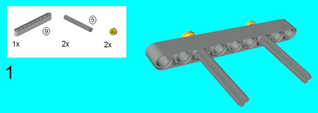
Figure 8-1. Insert the 5M axles as shown, and cap them off on one side with the half bushes
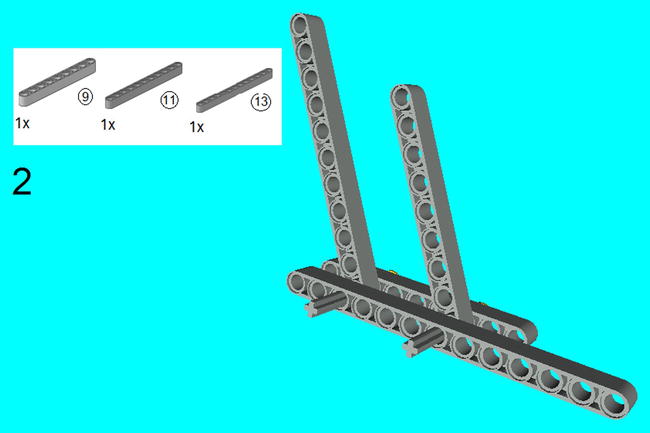
Figure 8-2. Slide on the 9M beam and 11 beam on the first through-hole on the axles, and slide on the 13M beam
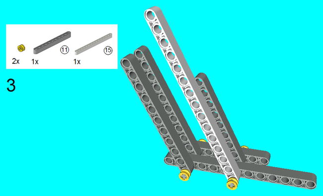
Figure 8-3. Slide on the 15M beam and 11M beam similar to the last step, and cap off the axles with half bushes
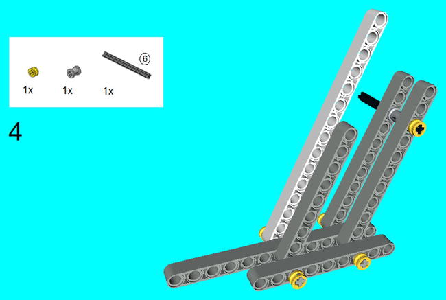

Figure 8-5. Slide on the 6M axle so it goes through the 11M beam at the end and the 15M beam as shown
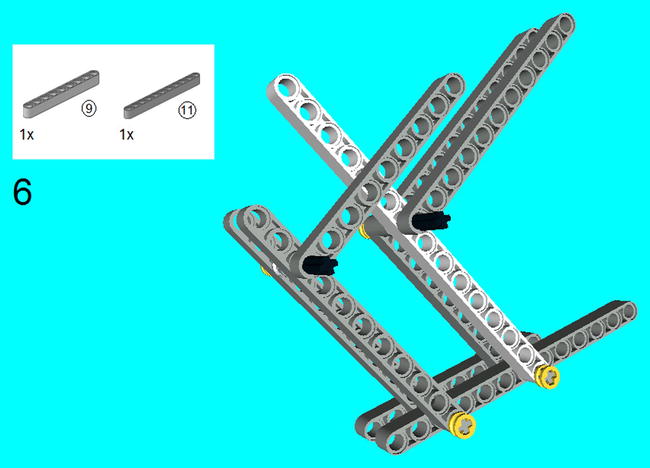
Figure 8-6. Slide an 11M beam on the 9M and 6M axle as shown
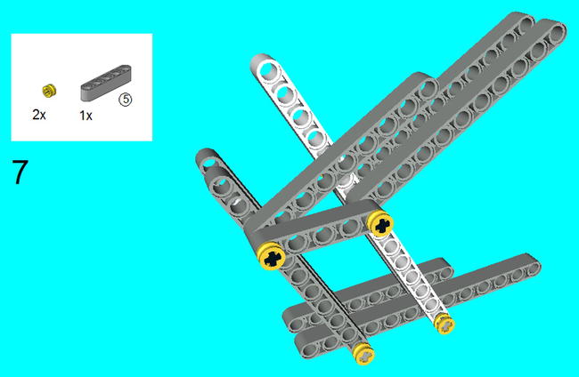
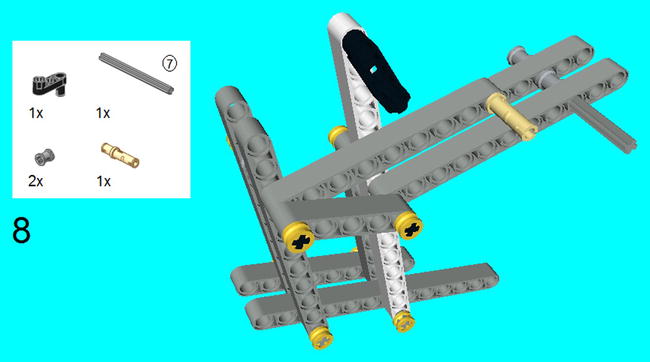
Figure 8-8. Snap on the steering knuckle arm on the 15M beam, and the 3M connector peg (without friction) on the 9M beam. Place the 7M axle as shown and secure it into place with the bushes
As you might have guessed, we cannot do a walking robot with a left leg and not have a right leg. You will notice that it uses the exact same pieces, but it is a mirror image of the left leg.
The one thing that I would like to note is the position of the 3M Levers in Step 3. In order for this model to walk, the levers on each side cannot be exactly the same. In fact, they must be 180 degrees off. In other words, if the 3M Levers point upward on the left leg, then they must point downward on the right leg. I will explain why later, but Figures 8-9 to 8-16 are the instructions that you will need.
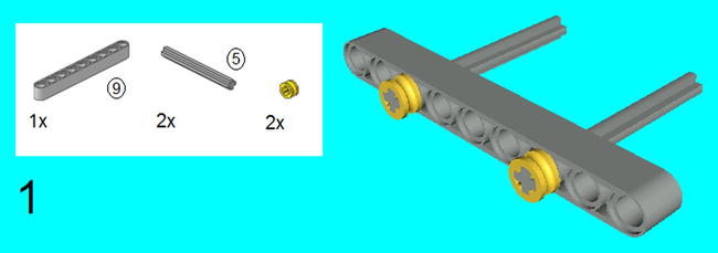
Figure 8-9. Insert the 5M axles as shown, and cap them off on one side with the half bushes
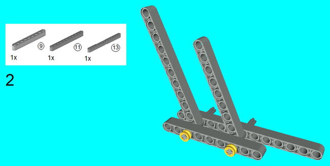
Figure 8-10. Slide on the 9M beam and 11 beam on the first through-hole on the axles, and slide on the 13M beam
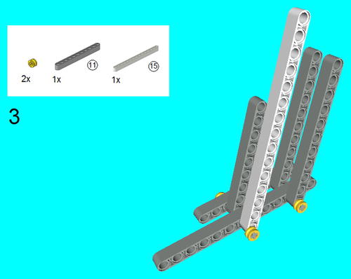
Figure 8-11. Slide on the 15M beam and 11M beam similar to the last step, and cap off the axles with half bushes
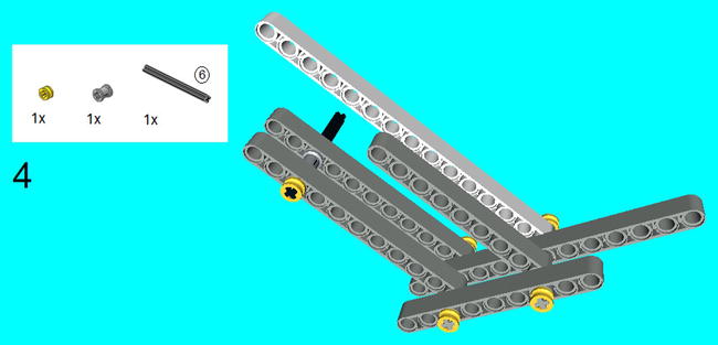
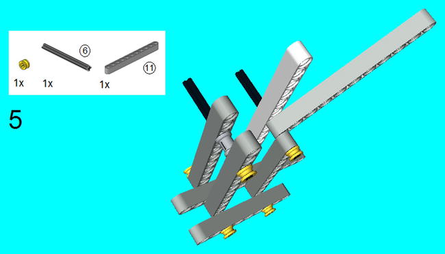
Figure 8-13. Slide on the 6M axle so it goes through the 11M beam at the end and the 15M beam as shown
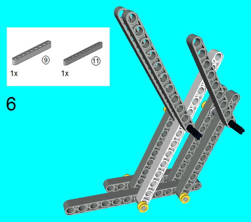
Figure 8-14. Slide an 11M beam on the 9M and 6M axle as shown

Figure 8-15. Slide a 5M beam on the 6M axles as shown, and secure it into place with two half bushes
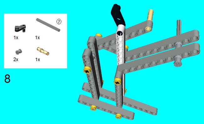
Figure 8-16. Snap on the steering knuckle arm on the 15M beam, and the 3M connector peg (without friction) on the 9M beam. Place the 7M axle as shown and secure it into place with the bushes
Project 8-3: The LEGO Robot Body
Now that the legs are created, it is only fair to show you how to create a body to put them on. There really is a lot on this body, as it houses the EV3 Brick, a Medium Motor, and two Large Motors, but they hold the legs on so they are stable, and keep them moving freely.
In case you are wondering, the legs are put on in the last step. You will need four to complete this, so make two copies of the left leg and right leg from Projects 8-1 and 8-2.
Another disclaimer that I need to make is that you may notice that some of the pieces are in colors that are not available in the Core and Expansion sets (this won't be apparent if you are reading the printed version, for example, but all the figures are available to download from apress.com, which allows you to see the colors). This is because this construction requires more than a few pieces than are available in the Core and Expansion sets combined, like the Robot Arm project of the last chapter. I would advise you to ignore the color of the piece and concentrate on the shape of the piece.
Figures 8-17 to 8-42 show the instructions for completing the robot.
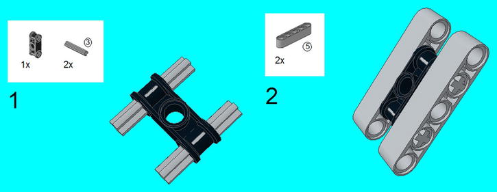
Figure 8-17. Center the 3M axles on the double cross block as shown. Center the 5M beams on the 3M axles, and they will be secured in place in the next step

Figure 8-18. Center the construction from Steps 1 and 2 on the 5 × 7 beam frame, and secure it into place with the six 3M connector pegs
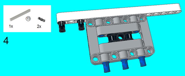
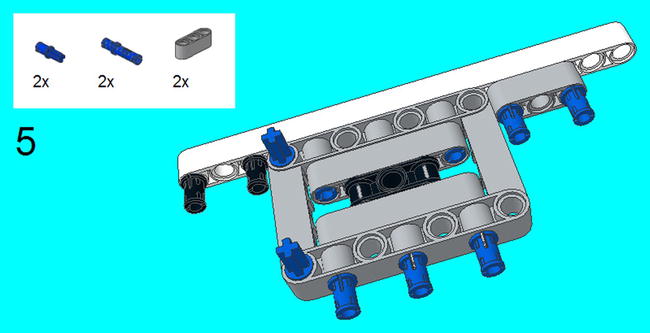
Figure 8-20. Snap on the connector peg/cross axles on the 5 × 7 beam frame. Center the 3M connector pegs on the edges of the 3M beam, and snap it into place as shown
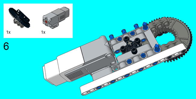
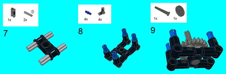
Figure 8-22. Repeat the steps from Step 1, but slide on four 90-degree angle elements with connector peg/cross axles. Slide on the 4M axle with stop through the center hole, and slide a 24-tooth gear on it
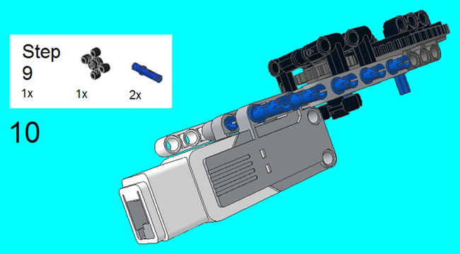
Figure 8-23. Snap on the creation from Steps 7-9 underneath the 5 × 7 beam frame and secure it with the 4M axle with stop with the angular wheel on top. Insert two 3M connector pegs on the Medium Motor
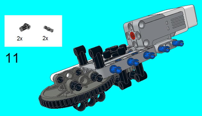
Figure 8-24. Slide on the zero degree elements on the connector peg/cross axles, and snap on the connector pegs on the turntable
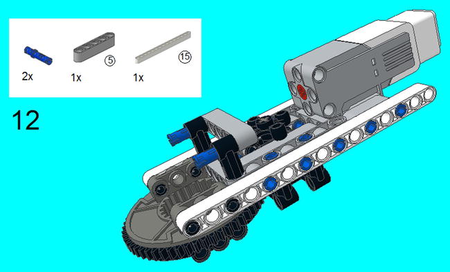
Figure 8-25. Center the 3M connector pegs on the zero degree elements. Snap on the 5M beam and 15M beam as shown
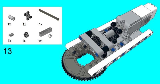
Figure 8-26. On the 8M axle with stop, place the 5M beam, tube, bush, 12 tooth bevel gear, and angular wheel so it is inserted in the Medium Motor
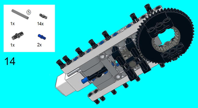
Figure 8-27. Insert the connector peg/cross axles on each end of the 180 angle elements, and insert it into the 5 × 7 beam frame as shown. Push the 5M axle (not seen in figure) so it is centered on the 180 angle element, and then snap in the connector pegs. Insert seven connector pegs on each side as shown
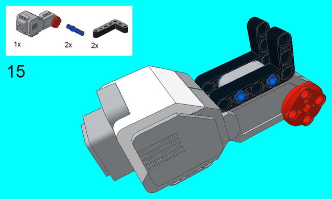
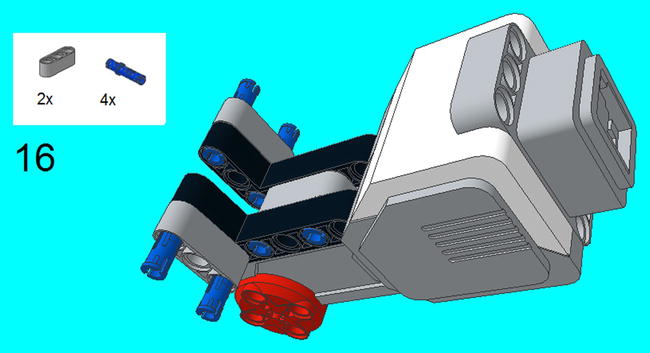

Figure 8-30. Insert two more 5 × 3 beams as shown
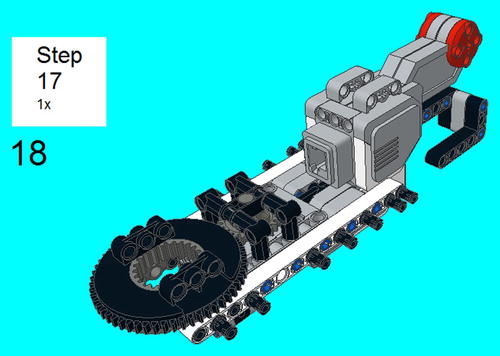
Figure 8-31. Insert the creation from steps 15-17 into the connector peg/cross axle from step 14. This isn’t exactly a stable connection, but it will be secured in the next step

Figure 8-32. Snap on a 13M beam on each side, and secure it into place with three friction snaps on each side

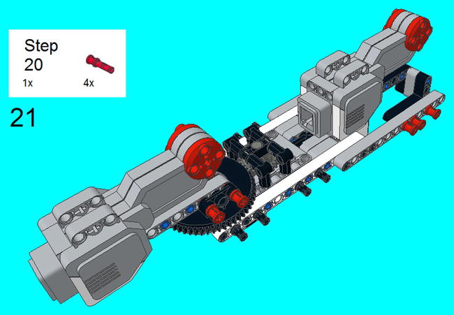
Figure 8-34. Secure the creation from step 20 to the turntable with the friction snaps

Figure 8-35. Snap on two 5 × 3 beams on connector pegs on the sides, and put connector pegs on the 5 × 3 beams as shown
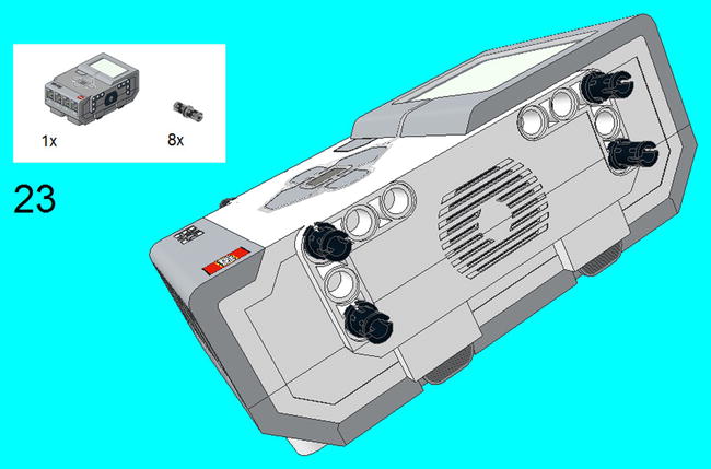
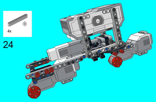
Figure 8-37. Using the 9M beams, secure the EV3 Brick from the last step to the rest of the creation

Figure 8-38. Insert the 3M connector pegs on both sides of the Large Motors, and slide on the 13M beams

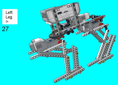
Figure 8-40. Insert two left legs (Project 8-1) on the left side. Note the position of the steering knuckle arms
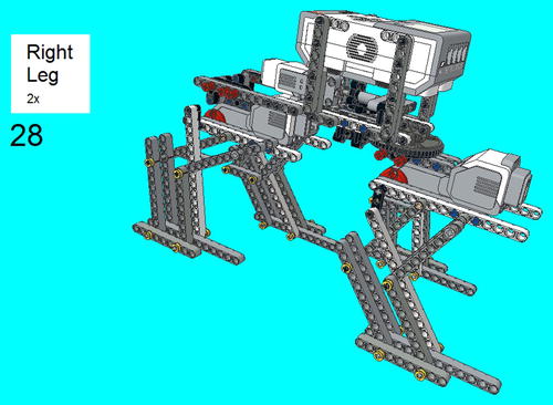
Figure 8-41. Insert two right legs (Project 8-2) on the right side. Note the position of the steering knuckle arms

Figure 8-42. Use connector cables to connect to the motors. Connect the Medium Motor to Port A, the front Large Motor to Port B, and the back Large Motor to Port C
![]() Note Just to make sure, remember that there needs to be a difference between the left and right leg. That is, the 3M levers in Steps 3 of both instructions have to be 180 degrees opposite. So if the 3M lever on the left front leg is pointing straight down, then the 3M levers on the left back leg must be pointing up. Manually adjust these legs if they are not correct.
Note Just to make sure, remember that there needs to be a difference between the left and right leg. That is, the 3M levers in Steps 3 of both instructions have to be 180 degrees opposite. So if the 3M lever on the left front leg is pointing straight down, then the 3M levers on the left back leg must be pointing up. Manually adjust these legs if they are not correct.
Programming the Walking Robot
Now that your four-legged robot is built, it is time to get it up and walking. You will find that walking it forward is simple and only requires the Tank programming block, but you need to make certain to begin walking when the Levers are 180 degrees off on each side, as stated in the Note above. Figure 8-43 shows examples of what you can do with Adjust by Seconds, by Degrees, and by Rotations. I highly recommend that both B and C have the exact number of rotations, or you might get some weird walking results.
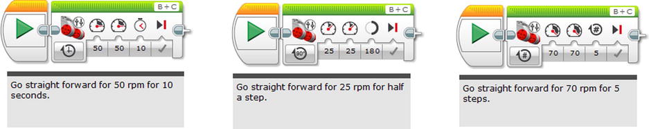
Figure 8-43. A program for forward motion on the walking robot
Of course, you are definitely going to want your walking vehicle to turn. You will notice that the turntable gives this ability to effectively swivel the front legs, and this gives the walker the ability to turn. I know that I have usually given very detailed instructions for programming, but now I am going to give you a crude program and let you fill in the details (see Figure 8-44).

Figure 8-44. A program for how to make the walking robot turn
You can see that the first programming block simply commands the two Large Motors to go forward, which ensures that the feet are moving forward. The second programming block commands them to stop. The third commands a turn for 90 degrees, and then stop. At the Fourth, only the Large Motor at Port B goes for five seconds, which is enough to start it turning. The fifth turns the front legs back 90 degrees, which straightens out the legs completely. Then the sixth commands the legs to go forward again, in a new direction.
You will notice that I did not specify how many actual degrees it will turn; I’m sure you have realized that the front legs won’t turn at a right angle, as it cannot turn that far. As with all the projects, you will want to play around with it so you can get it down exactly. This means a lot of trial and error, and possibly trial by error. Eventually, you can program paths for it to follow and let it roam.
In fact, I highly recommend programming situations with the brick buttons or all other facets of the programming blocks. For example, the Gyro Sensor could be used on the front in order to calibrate a precise turn. Still, this takes a little trial by error to make this precise, and eventually you will find the right combination to produce the same results over and over again.
Summary and Final Words
Constructing a walking robot creation is a complicated undertaking, but the LEGO MINDSTORMS makes it easier. The key is creating legs that can move and yet somehow not topple the construction over. The legs that I have provided in this chapter will work well if you construct them properly.
In addition to constructing the walking creation, it is also important to program it properly for forward movement, as well as turning. It is possible to program to roam all across the floor.
I used the walking robot as an example of the four questions one should ask before building, that is:
- What am I building?
- What will it do?
- How am I going to incorporate the sensors and motors?
- What kind of program will I need?
In the case of the walking robot, the construction was the hardest part. It required not only working legs, but also a way of motorizing them. The construction had to be made solid so that these motors and the EV3 Brick were held together without any danger of coming apart. The four legs had to bear the weight, and the steering mechanism had to be flexible but also strong. I guarantee that constructing any LEGO MINDSTORMS creation will be the hardest step, not to mention positioning the sensors and motors to be just in the right places.
Yes, creating a LEGO MINDSTORMS creation is all about building and then building it again. You have to go for stability as well as versatility. In other words, you have to build it strong and build it to work at the same time.
In addition to building the construction, you also will have to program it, which can often be as hard as the physical building process. Like building, this involves programming something, and then programming it again to insure that your creation does exactly what you say it will do.
Therefore, I give one last piece of advice in two parts: Keep creating, and keep trying.
I know that I have already talked about the importance of creativity, and want to let you know that it is something that the world needs more of. There are way too many LEGO builders who just imitate a set of instructions, and that is a good way to learn. The point of learning is to do something different, and not just follow in the footsteps of those who have gone before you. This is why you should challenge yourself to make LEGO MINDSTORMS creations that no one else has ever made.
Once you get that idea, the chances are that you won’t get it right the first time. You may have to build it, build it again, then re-design it, and repeat the process until you get it right. Even when you do get it right, you should build it again to make it even better.
As I said at the beginning of this book, I have no idea who is actually reading this. Perhaps you are not yet an adult, or you could be a senior citizen. Either way, I would give my two-part advice. Use the creative instinct that you have to make creations that are as lifelike as EV3 programming will allow them to be.