As stated in Chapter 2, games built with Unity are usually arranged in scenes. These scenes usually contain many objects to enhance them and make the game interactable and enjoyable. The goal is to have a concrete game with solid mechanics, good gameplay, and good graphics.
3.1 GameObjects and Prefabs
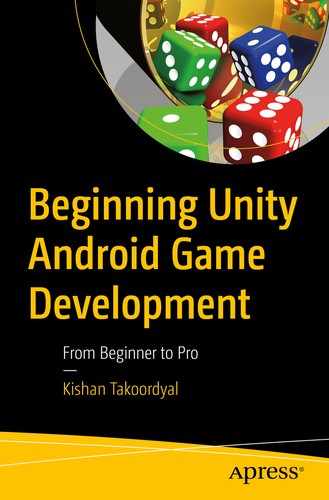
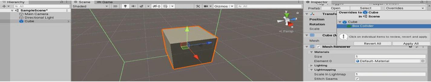
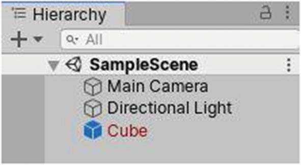
In Unity, objects in scenes are referred to as “GameObjects.” When you create a new scene, it contains a Main Camera and a Directional Light. These are GameObjects. Every object you find in the Hierarchy window is a GameObject. If you create a cube, it is also a GameObject.

Making prefabs
The GameObject you just turned into a prefab will now have a bluish tint to it in the Hierarchy tab. As for your prefab, you can just load another scene and drag it into the Hierarchy or Scene tab of that newly opened scene.
You can also make changes directly to a prefab. You just have to double-click it in the Project window. The Scene window will now have a bluish background, and you will now be able to see the children of that prefab (if it had any) and make changes to its properties, as well as to those of its children.

Opening prefabs
Overriding prefab properties
If you made a prefab, placed it in a scene, and don’t want it to be updated or overridden by future changes made to the prefab, you can always make that prefab instance become an independent GameObject, by right-clicking it in the Inspector and either clicking Unpack Prefab or Unpack Prefab Completely. For example, if you placed a prefab in one scene, and it has properties that completely differ from the ones in the original prefab, you might wish for that version to be completely independent.
Deleting prefabs
3.2 Components
Multiple components
In the Inspector window, you can change the values of components. You can also click the three dots at the top-right corner of components, in order to bring up more options, such as Reset, which will assign default values to the component, as if you just added it.
You can also copy and paste component values to two components at the same time, by clicking Copy Component. After selecting the GameObject having the component you wish to override the values of, click Paste Component Values. You can also copy components and directly paste them on another GameObject.
It should also be noted that a GameObject can have more than one instance of a particular component, although there are some exceptions to this. You can also reorder components on a GameObject, by dragging them up or down, or by using the three dots and clicking Move Up or Move Down.
Beside the three dots icon, there’s another button. Clicking it allows you to use a preset for the respective component.

Viewing the documentation

Adding components
3.2.1 Transform

The Transform component
The x axis is denoted by the red color and goes from left (-) to right (+) horizontally. The y axis is denoted by the green color and goes from bottom (-) to top (+) vertically, and the z axis is denoted by the blue color and goes from backward (-) to forward (+). All the axes are perpendicular to one another.
The Position Vector3 represents the position of the GameObject in the world in X, Y, and Z values. You can change these values by directly entering them into the text boxes beside the specific axis name, or by dragging your cursor from the axis name to the right (+) or left (-), in the Inspector tab itself.
The Rotation Vector3 represents the rotation of the GameObject in the world in x, y, and z values, and the Scale Vector3 represents the position of the GameObject in the world in x, y, and z values.
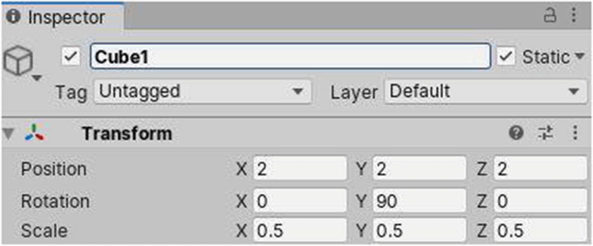
The Transform component of Cube1
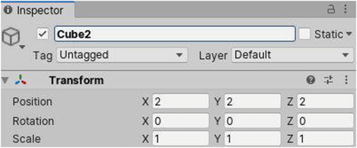
The Transform component of Cube2
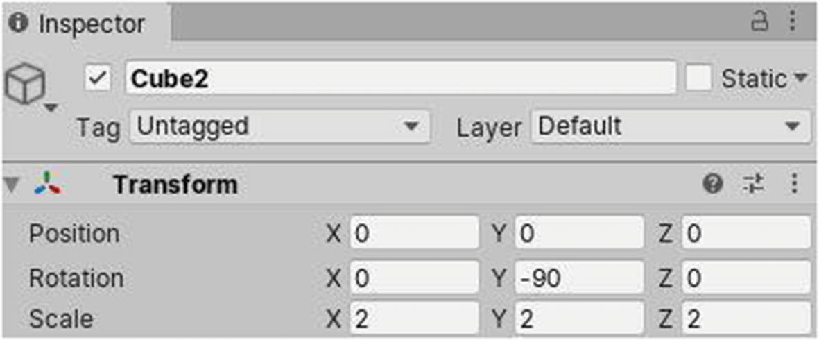
The Transform component of Cube2 if it is a child of Cube1
Because it is at the same position as Cube1, relative to its parent, the Vector3 position of Cube2 will be 0 on all axes. As its rotation is 0 everywhere, for it to maintain that, Cube2 must subtract 90 degrees on its relative y axis, to maintain that value of 0, because Cube1 is rotated by 90 degrees on its own y axis. As for the scale, it’s pretty self-explanatory: Cube2 is bigger than Cube1 by two times along all the axes.
3.2.2 Camera
A camera is the equivalent of our eyes in a video game. Everything you perceive in a game is being “seen” by a component known as Camera. Typically, at one particular time, you’d have only one main camera enabled in a single-player game, to show the player what they can see. If you’re playing a third-person game, the camera will be behind the main character you’re controlling and, thus, create the impression that the latter is being watched and followed by another entity. In a first-person game, the camera acts as the eyes of the character you’re controlling.

The Camera component
By default, it is set to Skybox, which, as you will learn later, is made up of a total of six images that usually complement one another to form a sort of cube that surrounds the scene.
Additionally, you can choose the Solid Color option and pick a color in the Background property just below.
If you choose Depth Only, nothing will be displayed in empty areas, and Don’t Clear will persistently display whatever was present in the last frame, if not overridden by anything.
Culling masks is a mechanism to control what gets rendered to this camera, based on the graphical elements that have been assigned to groups, called Layers.
With an orthographic camera, you have the ability to adjust the size of the camera, i.e., the area that it can “see” at one particular moment or frame.
With a perspective camera, you have the ability to choose its field of view, which is literally the process of adjusting the “angle” it can “see” from its center.
You can also adjust whether the field of view is along the Horizontal (x) axis, which goes from top to bottom, or along the Vertical (y) axis, which goes from left to right.
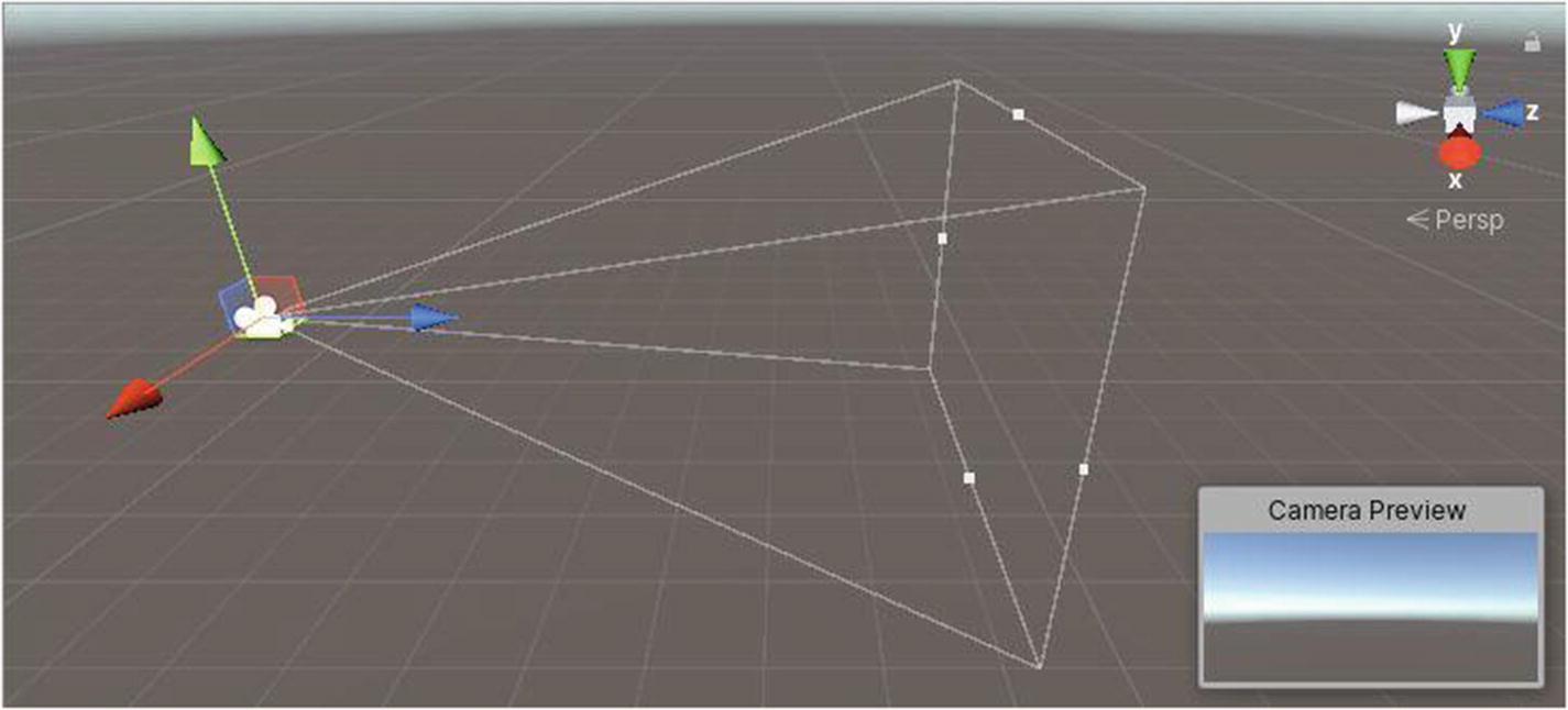
A perspective camera
Now come the Clipping Planes. Unity’s equivalent of 1 unit translates to 1 meter in the real world. For a camera, the Clipping Planes setting has a Near and a Far value. These two values represent the minimum and the maximum distance of a GameObject to a camera for the latter to render it. If the camera is closer than the Near distance to a GameObject, say, the camera is at the very center of the GameObject in question and the Near value is something like 0.5, it won’t get rendered. If now another GameObject is way far from the camera at a distance greater than the Far value, it won’t get rendered either.
The X and Y values allow you to adjust horizontally and vertically, respectively, where the render of the camera should be positioned.
The W and H values represent the portion of the screen that will be used for the render of the camera horizontally and vertically, respectively. A value of 1 represents using the full width or height of the screen, and a 0 represents none.
For example, if you were making a console racing game with a split screen feature for two players, you could have two cameras, each taking half of the screen, following one of the two players. Both cameras would have a W value of 0.5, an H value of 0, and a Y value of 0, but a different value of X to match the position of the left and right halves of the screen.
If you are using multiple cameras in a scene, you can set a different depth value for them. For example, if you’re making a game in which you can switch between a third-person and first-person view, you can make use of two cameras for either views, but as they both take up 100% of the screen real estate, the depth value determines what camera will be rendered to the player. In that example, the player will see what the camera having the highest depth value is “seeing.”
The rest of the settings will have a very brief description, and for simple or small projects, you probably won’t have to mess with those, and if you do, it’s better edit that of the project itself, rather than individual settings of cameras. The Rendering Path setting allows you to choose how GameObjects are rendered by a camera with respect to lighting.
The Target Texture allows you to assign a 2D render texture to a Camera component. That texture will then be updated with whatever the camera sees in the scene. This is useful for when you want to create a minimap in the form of a bird’s-eye view, for example. A camera can be set up to follow the player from above and look down (90, 0, 0). It could then output to a 2D texture that can then be assigned to a “rectangle” that will always be shown in the top-right corner of the screen.
Occlusion Culling is a popular technology that can drastically improve performance in some types of games. If you are making use of that technology and in particular want a camera to benefit from it, tick the respective check box. For Occlusion Culling to work properly, your scene has to be “baked” for this specific feature; otherwise, ticking the check box won’t result in any changes.
As for high dynamic range (HDR) and multisampling anti-aliasing (MSAA) rendering, they can make your game look better, but using MSAA, especially, has important performance costs.
Finally, ticking Allow Dynamic Resolution will allow the camera to scale render textures, if the platform you’re building your game for supports it.
3.2.3 Lighting
Lighting is very important in a video game. The position and rotation of a main light determines the portion of GameObjects that are visible, relative to their angle to the direction rays are cast from the light source and, thus, the direction that shadows are cast, as well as the size of these.

The Light component
In the Hierarchy window, you can create from four default types of light sources, namely, Directional, Point, Spot, and Area. A Directional light can be used to light a scene entirely and basically act as the sun. Point lights are used for more niche scenarios, such as, for example, torches in a medieval village. Spot lights can be used, for example, to simulate flashlights in a dark house for a horror game, and Area lights can be used to uniformly light up a defined area.
To keep this part simple, I will be basing explanations on Directional light sources only. The additional settings that are obtained with the other types of light sources are fairly self-explanatory.
If you’re using the Realtime light mode, GameObjects will be shaded as you play the game.
With Baked, you can “bake” your scene to make a type of lighting data asset that will be assigned to that light source automatically.
If you’re using Mixed, you will have a combination of Baked and Realtime lighting.
If you’re making games that require a moving light source or have GameObjects that are spawned progressively or randomly, it is better to use Realtime, because the lighting data will be more accurate. However, if you want to make some performance savings on the lighting side, and if objects are pretty much static in your scene, along with the lighting source, you might consider baking your scene prematurely and using Baked.

Quite normal intensity light on a cube
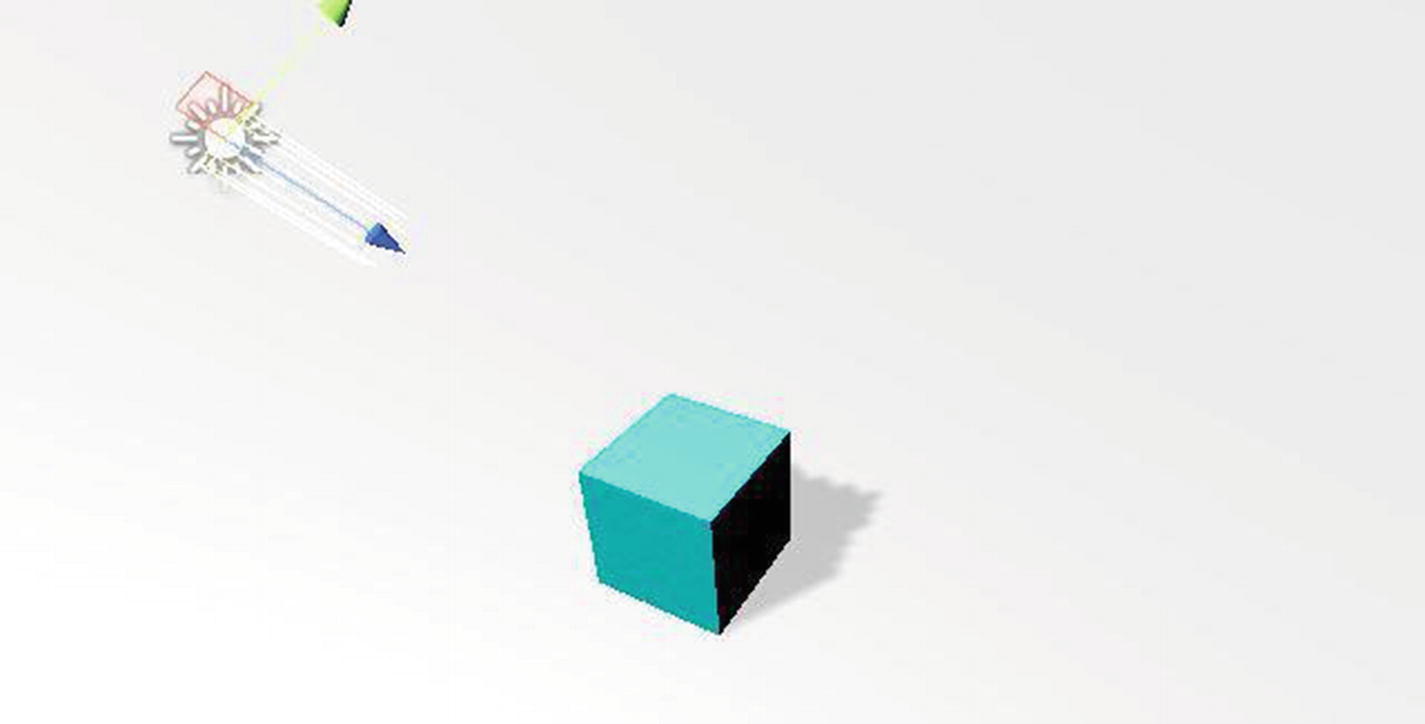
High-intensity light on a cube
The cookie property allows you to assign a 2D texture to the light source. The texture will be used as a mask. You can think of it as being a thick cardboard shape (in the form of a dinosaur, maybe) that’s brought in front of a light source (a bulb). This will define the shadows, silhouettes, or patterns that will be obtained when light from the source is cast. You can also edit the size of that cookie mask in the option just below it.
Ticking Draw Halo will create a blurry sphere around the light source, with a radius equal to its range (a property available if you’re using point or spot light sources) and of the same color as the light cast by the source.
Flare can be used to allow flares to be rendered by the light source in the scene, which might be useful if you’re making cinematics. The Render Mode can be changed to reflect the importance of lights in a scene, if you’re using some form of Forward Rendering. Finally, in a manner similar to that for cameras, you can select layers of GameObjects that will be affected by the light source in its Culling Mask property. GameObjects of Layers not selected won’t be affected in any way by that light source. In Unity’s documentation, you can find additional details on different light samples.
3.2.4 Renderer
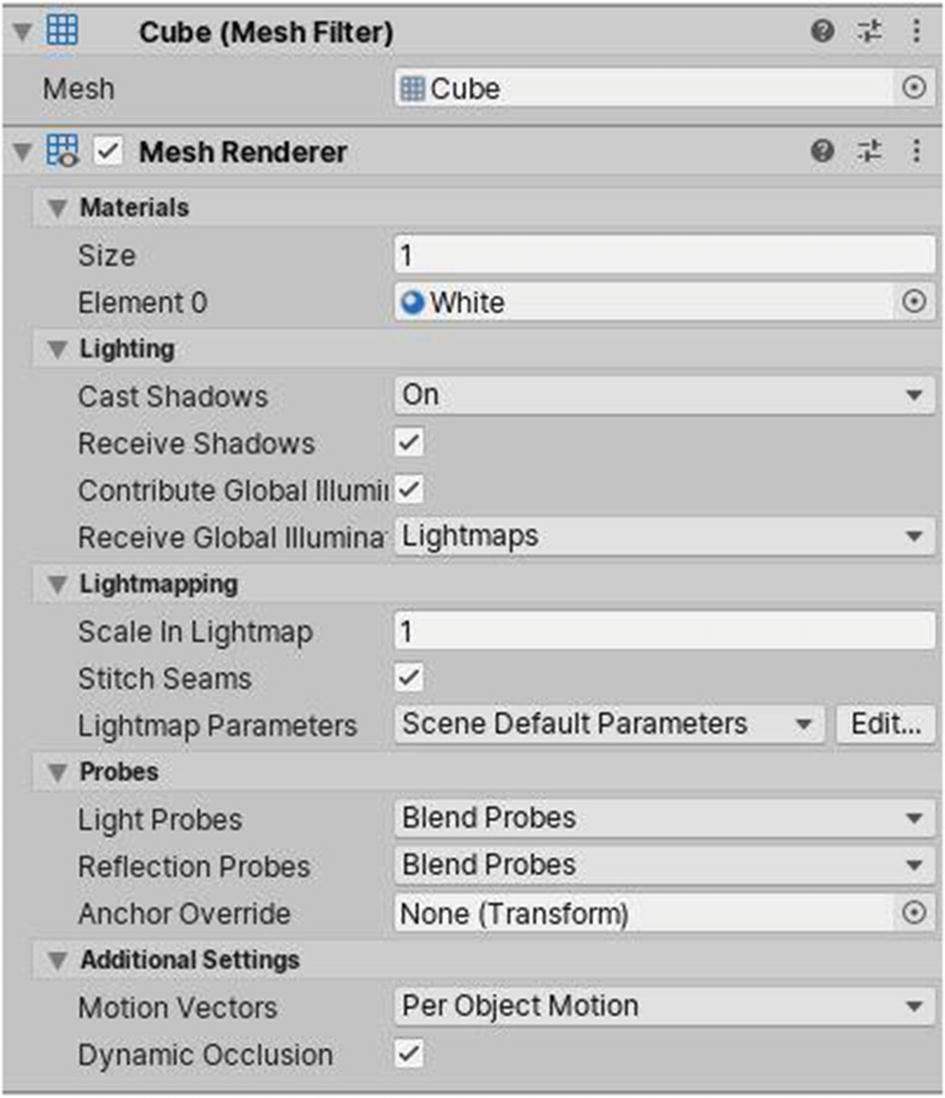
The Renderer component
In further topics, you’ll be learning what exactly materials are, but for now, just assume they’re colors.
A Renderer can make use of multiple materials, depending on how the mesh from the Mesh Filter component is set up. The lighting properties can be tweaked, if you want to customize how a GameObject receives or casts shadows.
You probably won’t need to mess with the other properties of Renderers when making games, but you can always access Unity’s documentation or manual to learn more.
3.2.5 Collider
Physics in a game depends on Rigidbodies and colliders. Colliders are the group of components that allow collision to occur. It is also common to see colliders being used as triggers. For example, getting sufficiently close to a nonplayer character (NPC) in a game may trigger a dialogue between the NPC and your character.
Box (Figure 3-18)
Sphere
Capsule
Mesh
Wheel
Terrain

The Box Collider component
Modifying the bounds of a Box Collider in the scene
In the Inspector window, changing the x, y, or z value of Vector3, known as “Center” is going to move the collider in the respective direction. Changing values of Size will make the collider bigger or smaller, respective of the axis on which you’re modifying its value. It should be noted that increasing or decreasing the scale transform for a GameObject will make its collider’s size decrease by a similar ratio. For example, if you create a cube and make all of its scale Vector3 values equal to 2, even if the size of its collider will be 1 on all axes, assuming you didn’t manually modify anything, the collider will still wrap around the full volume or size of the cube.
The Physics Material tab just above can be used to make the collider simulate a particular real material. For example, some physics materials can make a collider feel more slippery when you walk on it, such as ice, while others can make it feel like something that appears to have more friction, such asphalt, for example.
If we want an event to fire when two physics objects collide but not have them bounce off each other, trigger colliders are used. So, if you want a light to turn on as you move over a part of the floor, these will help. If you tick IsTrigger on a Collider component, the GameObject associated with it will appear to lack the ability to participate in collisions. In other words, you will be able to walk through the GameObject, even if it has a Collider component when its IsTrigger box is ticked. This is useful when you want to make trigger zones, for example, in a game where walking in an area triggers something to occur, such as playing a cutscene.

The Sphere Collider component

The Capsule Collider component
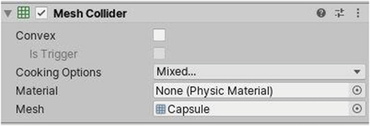
The Mesh Collider component
To make a Mesh Collider, use IsTrigger. You must mark it as “Convex” first. Ticking that will make the collider use a fair number of 3D regular shapes to cover the whole surface area and volume of the GameObject. Using Convex also allows collision between other GameObjects using a Mesh Collider. As far as possible, however, it is recommended that you use the other colliders discussed previously, rather than these, because they offer a performance boost, even if the Mesh Collider is marked as Convex.
3.2.6 Rigidbody
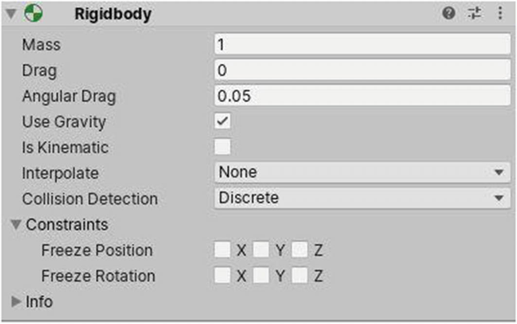
The Rigidbody component
The Mass property allows you to set the mass of an object. One unit is equivalent to 1 kilogram. Bigger values will make a GameObject feel heavier. Increasing mass will additionally make GameObjects less reactive to external forces (for example, explosions) and fall faster, if using Gravity.
Drag is the equivalent of air resistance, and the difference in this value is seen when making the GameObject fall from a height. Angular Drag is nearly the same, but it can be defined by how much air resistance will affect the GameObject’s rotation from torque. A value of 0 for either of these values can be translated as “this GameObject is not affected by air resistance.”
Not ticking Use Gravity will prevent the GameObject from falling down automatically, if left at a height above the ground with nothing below supporting it.
If Is Kinematic is ticked, the GameObject will not be affected by normal physics. In order to make the GameObject move or affect its position or rotation, you must manipulate its respective Transform values. This is useful for making moving platforms.
Interpolation can be used to make the GameObject feel smoother, if there’s jerkiness in the movement of the player character of a game, for example. Setting Interpolate to Interpolate will smooth the Transform, based on that of the previous frame, while in Extrapolate, the Transform will be smoothed, based on that of the estimated next movement. You’ll learn more about Interpolation when we start coding.
The Collision Detection system can be changed from Discrete to one of the Continuous modes, if a GameObject is moving so fast that it’s able to go through other colliders, because the Collision Detection system isn’t detecting it fast enough. Using modes other than Discrete will have performance costs.
Finally, you can set constraints for a GameObject. Ticking either check box will not allow the GameObject to move or rotate on the respective axis/axes. This doesn’t mean that it won’t via code or script. It just means that normal physics applied to the Rigidbody (e.g., a collision) won’t have any effects to it.
3.2.7 Audio Source and Listener
An Audio Listener component is usually found on the main Camera GameObject. It implements a microphone-like device. It records the sounds around it and plays them through the player’s speakers. You can only have one listener in a scene. For example, if at one point in your scene you had a car motor running and producing sound, the sound would play at a higher volume when the camera got closer to it.
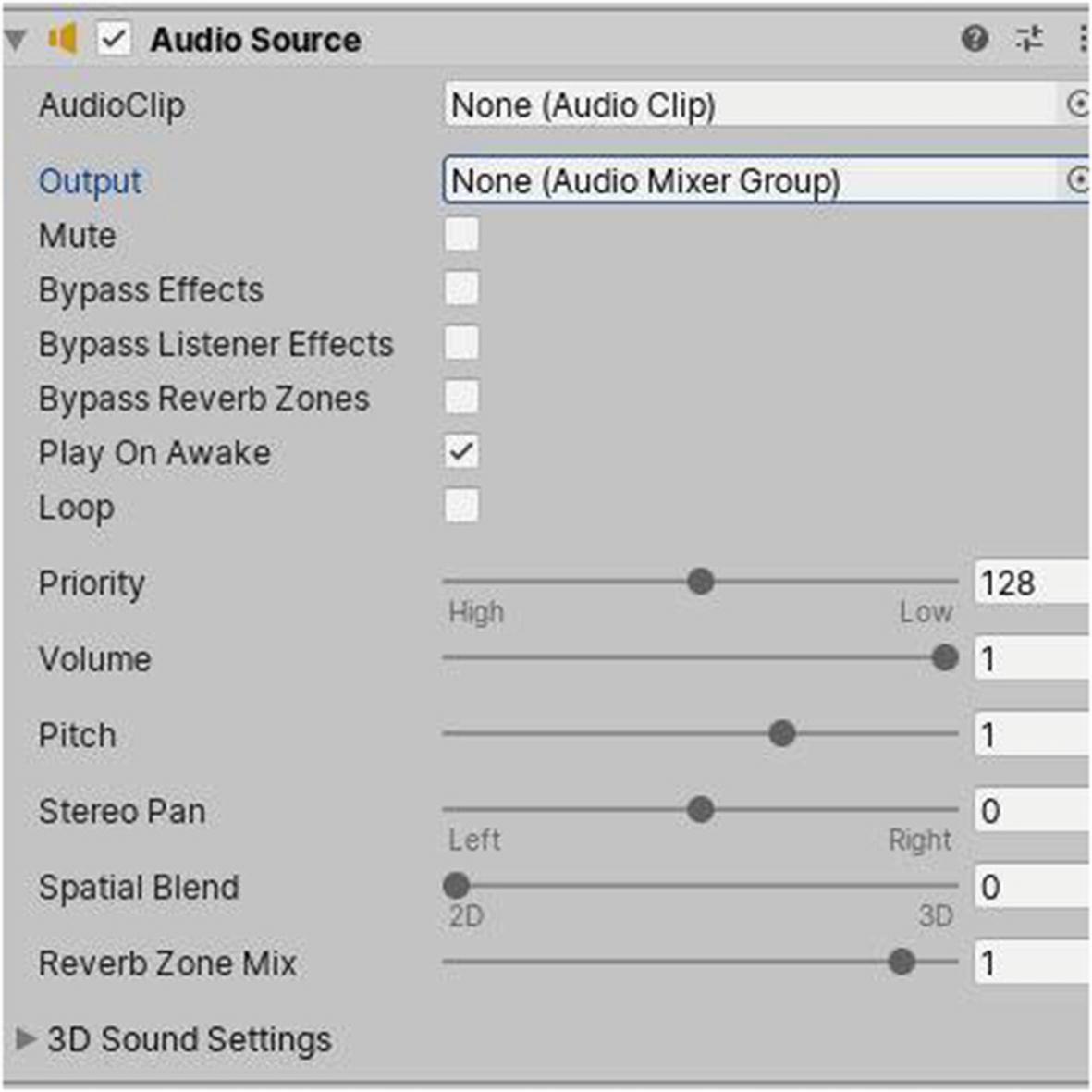
The Audio Source component
The first property of an Audio Source component is the AudioClip. This is usually an audio file that in Unity you import as an asset. The Audio Mixer Group is another component or asset you can use to further personalize the quality of sound that will be produced.
Ticking Mute disables Audio Listeners from picking up the audio produced by its Audio Source. Later, you can tick bypasses, to prevent the sound produced by the Audio Source from being affected by other effects, either Listener ones or those resulting from another type of component, with Reverb Zones applied to it accordingly.
Play On Awake will make the Audio Source play the assigned Audio Clip as soon as the scene loads, and Loop will make the Audio Source replay the Audio Clip from scratch, each time it has completed playing automatically.
If you have multiple Audio Sources in a scene, you can set a different priority for each, using its Priority slider. If, for example, an Audio Listener is equidistant from two Audio Sources, the one that has the lowest Priority slider of the two will sound louder than the other.
What the Volume slider does is pretty obvious. An Audio Source with a volume of 1 will play its assigned Audio Clip as loud as the maximum volume that the speaker has been set to output at. Note that the sound produced by an Audio Source having a volume of 0 won’t be heard.
The Pitch slider is used to set the frequency of the sound produced by an Audio Source. It can also be used to speed up or slow down the sound.
The Stereo Pan slider sets the amount of the output signal that gets routed to Reverb Zones. The amount is linear in the (0–1) range, but allows for a 10 dB amplification in the (1–1.1) range, which can be useful to achieve the effect of near-field and distant sounds.
Spatial Blend, Reverb Zone Mix, and 3D sound settings are beyond the scope of this book.
3.2.8 Particle System

Particle System in a scene
Playback Speed can be changed to view the Particle System running at a speed other than that specified.
Playback Time contains a value that represents the number of seconds that have passed since the Particle System has started running.
Particles is the number of generated particles that is currently active for that Particle System, and Speed Range is the min-max value for the speed of these particles.
Simulate Layers allows you to simulate the Particle System on layers other than those of the GameObject that holds it.
Ticking Resimulate will make changes applied to the Particle System show immediately.
Show Bounds will make a 3D volume appear in the Scene window, which will indicate the maximum distance that particles can travel in that system.
Finally, if ticked, the last check box, Show Only Selected, will hide all unselected Particle Systems in the current effect.
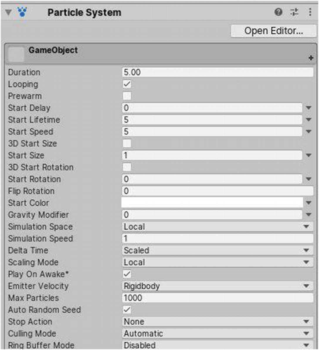
The first settings in a Particle System component
Start Delay is the amount of time the system will wait before it starts emitting. Start Lifetime defines after how many seconds a particle will be automatically destroyed after it is emitted. Start Speed is the speed at which a particle will travel initially when it is emitted.
Start Size or 3D Start Size can be used to define the size of a particle. Start Rotation or 3D Start Rotation defines its rotation. Flip Rotation can be used to flip the rotation of particles. Start Color changes the color of the particle when it is created.
Gravity Modifier can create particles affected by gravity. A value higher than 0 will make the particles fall down quicker. A value lower than 0 will act according to the previous statement, but the particles will go up instead of down, and 0 will render the particles entirely unaffected by gravity.
If set to Local, particles will move relative to the Transform of the GameObject their Particle System is attached to.
In World, they move relative to the world or scene.
In Custom, you can specify another Transform to make the system relative to.
Simulation Speed is the multiplier at which the Particle System will play back. Changing the Delta Time mode is useful for playing effects while Paused, if using the Unscaled option.
Scaling Mode serves to resize particles relative to the entire hierarchy, local particle node, or only apply scale to the shape.
Ticking Play On Awake will make the particle system start running automatically.
Emitter Velocity allows you to change the mode either to Transform or Rigidbody, depending on how to calculate velocity if the system is moving.
Max Particles defines the maximum number of particles in the system at one particular moment. If this number is reached, no more particles will be emitted until there are fewer particles than the number defined.
Ticking Auto Random Seed will make the simulation different each time the effect is played.
In Stop Action, you can define what to do if the Particle System is stopped and all particles have been destroyed. You can, for example, choose to disable the Particle System component or destroy the GameObject that has the latter as component.
The Catch-up mode pauses offscreen simulations but performs a large simulation step when they become visible, giving the appearance that they were never paused.
Automatic uses Pause mode for looping systems and AlwaysSimulate if not.
AlwaysSimulate will never Pause the simulations, even if offscreen.
When Ring Buffer Mode is set to Enabled, particles remain alive until the Max Particles buffer is full, at which point new particles will replace the oldest, instead of dying when their lifetime has elapsed.
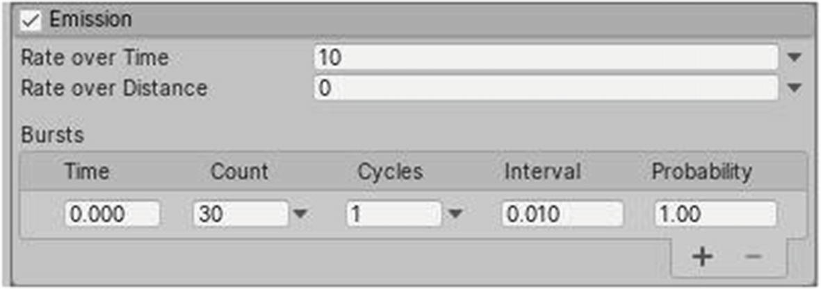
Emission property of the Particle System component
The value in the Rate over Time property represents the amount of particles that will be emitted per second. That in Rate over Distance is the same as Rate over Time but acts per unit second instead.
The Bursts array allows you to emit particles at specific time frames. Its Time property lets you choose when to emit bursts of particles, and Count designates the number of these particles to emit. Additionally, you can set a curve or create a range for the number of particles to emit, by choosing another setting in the drop-down other than the value.
The value in Cycles allows specifying how many times to repeat the burst. You can set it to infinity by choosing that property when accessing its drop-down menu.
Interval lets you repeat that burst every x seconds, and Probability is a value from 0 to 1. If Probability is set to 0, the burst will never occur, and if set to 1, it will always occur. A value of 0.5 will have the burst occur 50% of the time or not occur 50% of the time.
You can add more sets of values by clicking the plus icon below or remove sets by clicking the minus icon.

Shape property of the Particle System component
A higher value of Angle will make emitted particles go in more directions, and increasing the Radius will increase the volume that particles can cover. Radius Thickness can have a value from 0 to 1. A value of 0 will make emitted particles seemingly have a denser value.
The value in Arc represents the maximum angle from the center of the emitter from which particles can be spawned. A value of 0 will make particles emit from the center of the emitter only, while a value of 360 allows particles to be emitted at any point along the area of the base of the emitter. For example, as we are using a cone, a value of 360 makes particles spawn at any point found on the small circle that forms the base of the emitter.
Mode allows you to choose how particles are spawned around the Arc. A mode of Random makes them spawn at any position with respect to the original Arc value, and Spread lets you choose to spawn particles at specific angles. A value of 0 disables this behavior.
The value that Emit from uses can be changed to specify from where you want particles to be emitted, either from the Base or the Volume itself. Using a Texture 2D asset, you can modify from where particles will sample their color.
The Vector3 Position allows you to move the emitter volume from the position of the Transform of its GameObject. Rotation and Scale play a similar role.
Ticking Align To Direction will automatically aligns particles, based on their initial direction of travel.
Randomize Direction takes a value of 0 to 1. A value of 1 will override the initial direction of travel of particles with a random direction.
Similarly, Spherize Direction overrides that initial direction of travel with a direction that projects particles outward from the center of the Shape Transform.
Finally, Randomize Position moves the starting position by a random amount, up to the maximum value it contains.
Moving on to the four buttons at the bottom of the Shape Property, the first one can be clicked to toggle on or off the Shape gizmo editing mode. This acts in the same way as the Modify Collider button for colliders, allowing you to resize the boundaries or shape of the emitter volume in the Scene window.
The three other buttons allow you, respectively, to move, rotate, or scale the emitter volume, using guides such as arrows, which will appear in the Scene window as you toggle them.
The values in Velocity over Lifetime and Limit Velocity over Lifetime can be tweaked to make the particles gain or lose speed with time, respectively.
Inherit Velocity allows you to control the speed particles inherit from the emitter itself.
Force over Lifetime and Color over Lifetime contain properties that can be modified to make particles gain/lose force and exhibit color changes with time, respectively.
Color by Speed works in a way similar to Color over Lifetime but acts as per the speed of particles, rather than with time. Size and Rotation over/by Lifetime or Speed act similarly.
External Forces can be modified to make particles be affected by wind, for example. Noise lets you add turbulence to the movement of particles, and Collision lets you specify multiple collision planes that particles can collide with.
Triggers allow you to execute script code, based on whether particles are inside or outside collision shapes. Sub Emitters allow each particle to emit particles in another system. Texture Sheet Animation allows you to specify a texture sheet asset and animate/randomize it per particle. Lights lets you control light sources attached to particles, and Trails lets you attach trails to particles (which you will learn more about in the next section, “Trail Renderer”). Custom Date is quite complex and allows particles to interact with scripts or shaders.
As for the properties of Renderer, well, you can define how particles are rendered, i.e., control their color, trails, rendering mode, sorting mode, minimum/maximum size, alignment with respect to the camera, flip/pivot along axes, and how they interact with shadows/lights.
3.2.9 Trail Renderer

A trail from a Trail Renderer component on a GameObject in the scene
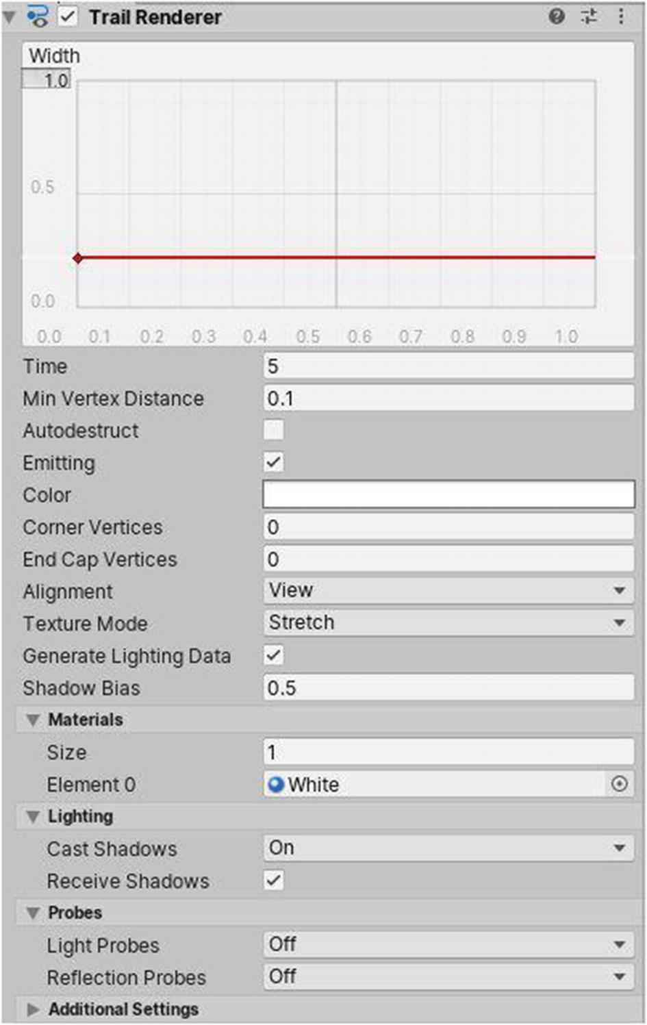
The Trail Renderer component
The values of the Time axis (x axis) actually correspond to a percentage of the total time the trail has been set to render, as defined by the Time property (in our case, 5). This time value of 5 can be interpreted as the maximum time that the trail will persist. Following is an example. If the value is set to 10, and a car is continuously being driven, pieces of the trail will continuously be spawned, which will appear as if the trail will reach a maximum length value of 10. The trail will remain this long (appearing like a long rectangle), because new pieces are being spawned to replace the previous one from the car, at a maximum value of 10, until the car brakes. The trail will then become shorter and shorter, until it has a length of 0. This will take 10 seconds to occur, because each piece will be destroyed 10 seconds after it has been spawned, with the farthest pieces being the ones to disappear first.
The values of the Width axis (y axis) will correspond to the width of the trail formed at a particular point in time.
Min Vertex Distance is the minimum distance at which to spawn from the previous one a new point on the trail.
Ticking Autodestruct automatically destroys the GameObject having that Trail Renderer as component when there is no trail. Unticking Emitting will pause trail generation.
Color allows you to set a gradient for the color along the trail. Corner Vertices is the amount of vertices to add for each corner. End Cap Vertices is the number of vertices to add at each end of the trail.
Alignment lets you rotate trails to face their transform component or the camera. If you choose to use the TransformZ mode, lines will be extruded along the XY plane of the Transform.
Texture mode, on the other hand, can be set to another mode, depending on how you want coordinates to be placed.
If ticked, Generate Lighting Data will generate data for shaders associated.
A Shadow Bias can be applied to prevent self-shadowing artifacts. A value of 0.5 represents 50% of the trail width at each segment.
You’ll learn about materials in the next section, but for now, just assume that they define the color of the trail.
Lighting lets you choose how shadows are cast or received. Similarly, Probes, are about lighting and reflections.
3.3 Materials
Creating a material

Applying a material to a GameObject with a Renderer

Properties of a material
By default, a created material will use the Standard Shader. This can be changed, matching specific requirements. The little transparent squares that appear beside properties can be assigned 2D textures, so that they don’t appear plain, as they are by default.
Albedo is the main color of the material, and you can pick another color. All instances of objects that are using that material will display and apply the changes in real time.
The Metallic and Smoothness sliders will make the color of the material appear more or less metallic and smooth, respectively. You can also change the source to Albedo Alpha to simulate another effect.
As stated, you can set 2D textures for the normal, height, occlusion, and detail masks. After ticking Emission, you can make the material emit HDR colors.
Tiling and Offset are useful if, for example, you have a material using a grid 2D texture. Changing these values will make the material repeat itself or move along axes.
I won’t go into detail about Secondary Maps and the other options, because these are not required for the purposes of this book.
3.4 Tags and Layers
As mentioned, tags can be used, for example, to identify what object collided with an enemy during a shooting game. If it was the player, we should remove health from him; otherwise, if it was a bullet, damage should be taken by the enemy.
Layers can be applied to GameObjects too. In the Editor, you can define whether a layer of GameObject can collide with another layer of GameObject. By default, when you create a Layer and assign it to a GameObject, it can collide with all objects, using existing Layers, if you don’t modify anything. Layers can also be used to define what objects are rendered by the camera or affected by a particular light source.

An example of a Layer Collision matrix

Tags and layers

Applying tags and layers to GameObjects
3.5 Scripts
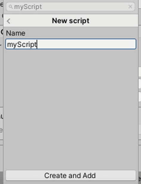
Creating scripts
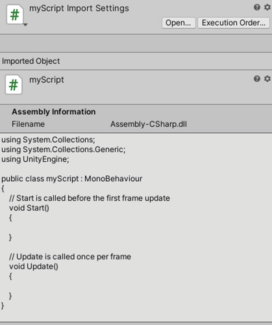
Viewing scripts in the Inspector
If you double-click the script, it will be opened in the code editor you set in Edit ➤ Preferences. The first three lines of any new script created serve to reference namespaces that contain classes. These will allow you to write code that makes use of popular and important data types, such as lists and arrays. The using UnityEngine; line will let you interact easily with other components in the engine, via your scripts.
Code you write in a script is normally placed between its starting and closing curly brackets. The : MonoBehaviour part is what’s going to make your script actually behave like a component in Unity.
Next, if you want to declare global variables, you can do so outside any functions, within the curly brackets of the class.
Code written in the void Start() {} function will run once when you enter Play Mode. That written in void Update() {} will be executed once per frame. If your game is running at 60 FPS, the code in the update function will run 60 times in a second.
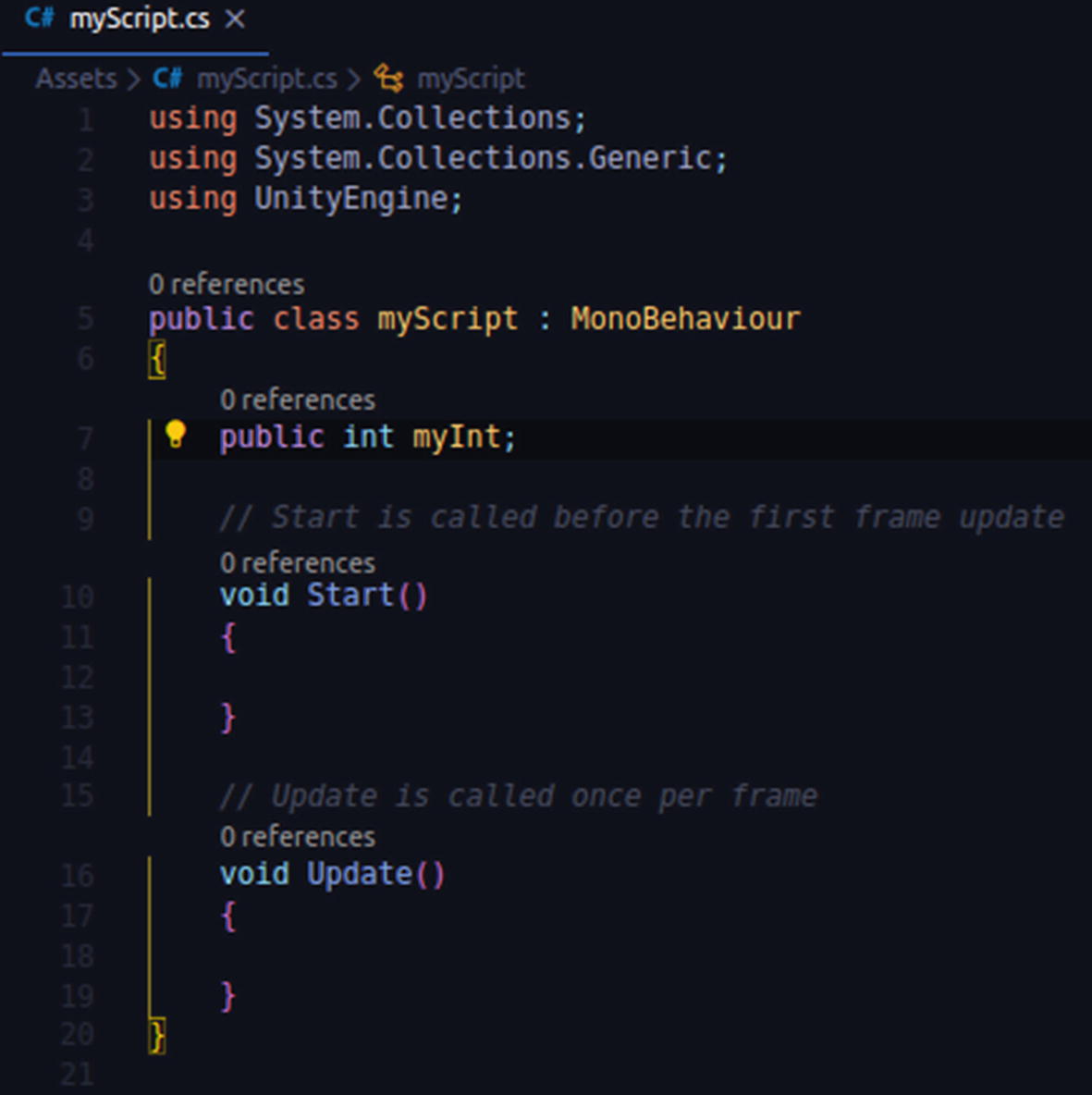
How a script is by default + a global integer variable: myInt

Viewing and modifying script variables from the Inspector