In this chapter, you will learn about how to use the Wearic push-button textile element with your wearables. A push-button textile consists of two soft pushbuttons. By programming the micro:bit, these buttons can be used to control actuators such as LEDs, heating textiles, servos, and so on. The skills you gain in this chapter will help a lot when it comes to following the rest of the chapters in this book.
3.1 The Push-Button Textile Element

The push-button textile element
The common snap (pin) on the push-button textile element can be used for both buttons. For example, if you want to connect button A to the micro:bit, you can use the button A pin and the common pin.
3.2 Building the Hardware
micro:bit
Wearic push-button textile element – Provides two momentary pushbuttons
Three alligator cables
2 × AAA battery holder with batteries
We’ll provide the wiring diagrams under each project that you are about to build shortly.
3.2.1 Using a Single Button As an On/Off Switch: Press and Hold to Turn On and then Release to Turn Off
First, let’s start with a simple program that detects a button press. This will help you when you want to activate something attached to your garment (e.g., LEDs, servos, heating elements, etc.) by pressing and holding a button. When you release the button, the actuator will turn off. If you want to turn on something manually for a short time, then this is one of the good solutions.

Button A on the push-button element is connected to the micro:bit pins 1 and 3V
Step-by-step instructions to build the code
Step | Blocks | Description |
|---|---|---|
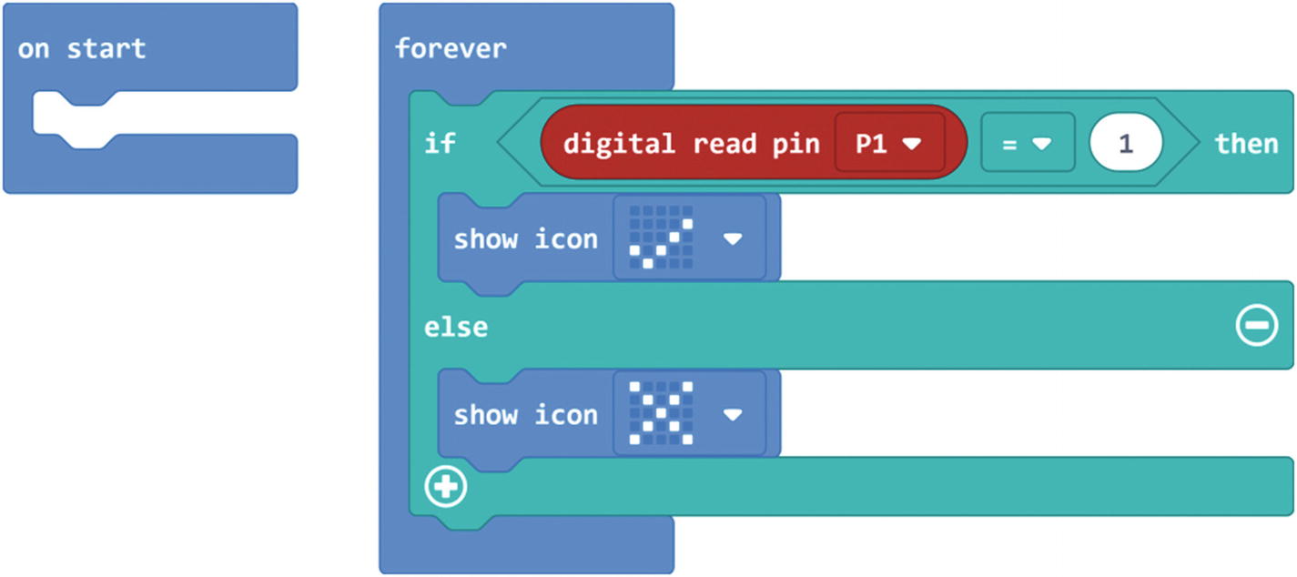
1 |
| Use the forever block to build the following code. Every block you place inside the forever block will repeat until you power off/restart the micro:bit. |
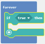
2 |
| Place an if-then-else block into the forever block . |
3 |
| Replace the true (boolean operator) block of the if part with an equals (number comparison) block. |
4 |
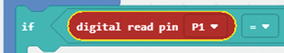
| Replace the left-hand number of the number comparison block with a digital read block. Then choose P1 from the drop-down list. |
5 |
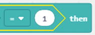
| Replace the right-hand number (0) of the number comparison block with 1. |
6 |
| Place a show icon block into the then part of the if-then-else block. Then choose the YES icon from the drop-down list . |
7 |
| Place another show icon block into the then part of the if-then-else block. Then choose the NO icon from the drop-down list. |


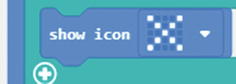
Code to turn on something when pressing and holding a button. Release the button to turn off
Download and flash the code onto the micro:bit. After completion, the program will immediately start to run and display the NO icon on the micro:bit display. That means button A is in its “off” state. First, press and hold button A on the textile button element. The micro:bit display will show the YES icon. That means button A is in its “on” state. Now release the button. The micro:bit will display the NO icon again. The program continuously listens to what's happening to button A and displays the button status accordingly.

Using a single button to control an LED (Press and Hold to Turn On and then Release to Turn Off)

Code to turn on something connected to pin 0 when pressing and holding a button. Release the button to turn off
3.2.2 Using Both Buttons As an On/Off Switch: Press One Button to Turn On and then Press the Other Button to Turn Off
Now you will use both buttons on the textile button element to control an actuator. As an example, when you press and release button A, the actuator will turn on. Then when you press and release button B, the actuator will turn off. If you want to turn on something manually for a long time, then this is a good solution.

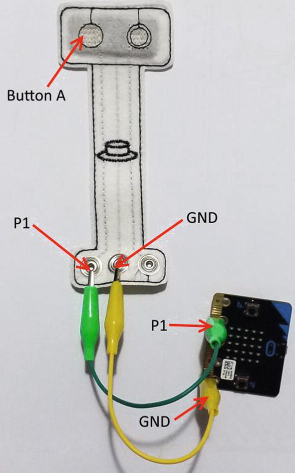
Button A on the push-button element is connected to the micro:bit pin 1, button B to pin 2, and common to 3V
Step-by-step instructions to build the code
Step | Blocks | Description |
|---|---|---|
1 |
| Use the forever block to build the following code. Every block you place inside the forever block will repeat until you power off/restart the micro:bit. |
2 |
| Place an if-then block into the forever block . |
3 |
| Replace the true (boolean operator) block of the if part with an equals (number comparison) block. |
4 |
| Replace the left-hand number of the number comparison block with a digital read block. Then choose P1 from the drop-down list. |
5 |
| Replace the right-hand number (0) of the number comparison block with 1. |
6 |
| Place a show icon block into the then part of the if-then block. Then select the YES icon from the drop-down list. |
7 |
| Place another if-then block into the forever block after the first if-then block . |
8 |
| Replace the true (boolean operator) block of the if part with an equals (number comparison) block. |
9 |
| Replace the left-hand number of the number comparison block with a digital read block. Then choose P2 from the drop-down list. |
10 |
| Replace the right-hand number (0) of the number comparison block with 1. |
11 |
| Place a show icon block into the then part of the if-then block. Then select the NO icon from the drop-down list |


This code checks the status of both buttons A and B
Now download and flash the code onto the micro:bit. After uploading completes, the code will start to run immediately. When you press and release button A, the YES icon will show up on the micro:bit LED matrix. When you press and release button B, the NO icon will display on the micro:bit LED matrix.

Using both buttons to control an LED (Press One Button to Turn On and then Press the Other Button to Turn Off)
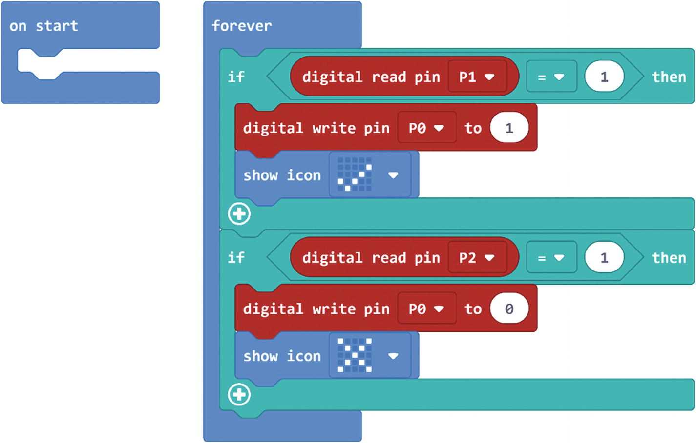
This code checks the status of both buttons A and B and then turns on/off pin 0 accordingly
3.2.3 Using a Single Button As an On/Off Switch: Press Once to Turn On and then Press Again to Turn Off
In this project, you will program a single button on the push-button textile as an on-off switch. The button will work similarly to the power button on your television’s remote control.
For the first time, when you press and release the button, it behaves as an “on” operation of a switch. The second time, when you press and release the button, it behaves as an “off” operation of a switch. Each time, the on/off button toggles between those functions.
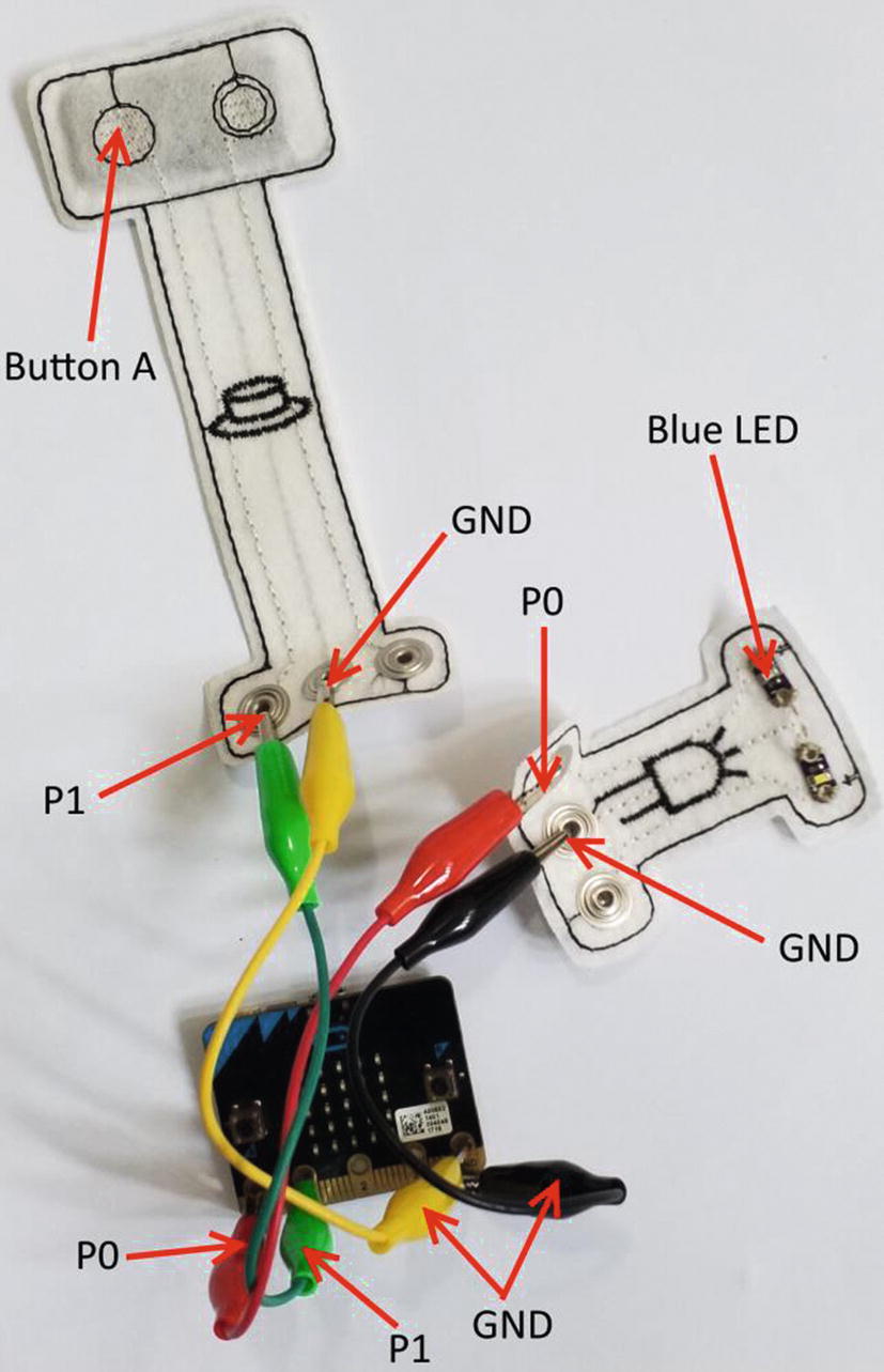
Button A on the push-button element is connected to the micro:bit pin 1 and GND
Step-by-step instructions to build the code
Step | Blocks | Description |
|---|---|---|
1 |
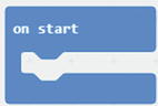
| Use the on start block to build steps 2–3. |
2 |
| Create a variable named item. |
3 |
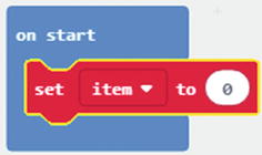
| Place the set item to block into the on start block . |
4 |
| Use the on pin P1 released block to build steps 5–13. |
5 |
| Place the set item to block into the on pin P1 released block. |
6 |
| Replace the number 0 with an add block. |
7 |
| Replace the left number of the add block with the variable item you created earlier. Then replace the right number of the add block with 1. |
8 |
| Place an if-then-else block into the on pin P1 released block after the set item to block . |
9 |
| Replace the true block of the if-then-else block with the equals (number comparison) block. |
10 |
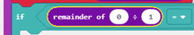
| Replace the left number of the equals block with the remainder of block. |
11 |
| Replace the left number of the remainder of block with the variable item. Then replace the right number of the remainder of block with 2. |
12 |
| Place a show icon block into the then part of the if-then-else block. Then select the NO icon from the drop-down list . |
13 |
| Place a show icon block into the else part of the if-then-else block. Then select the YES icon from the drop-down list. |


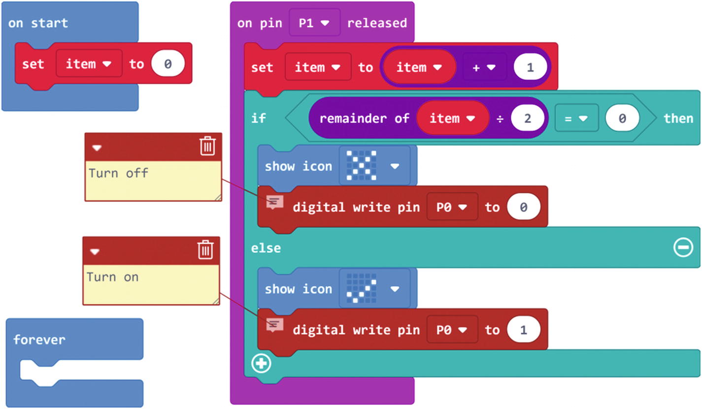
Press button A once to turn on, and then press again to turn off
Now download and flash the code onto the micro:bit. After uploading completes, the code will start to run immediately. When you press and release button A, the YES icon will display on the micro:bit LED matrix. When you press and release button A again, the NO icon will display on the micro:bit LED matrix.

Using a single button to control an LED (Press Once to Turn On and then Press Again to Turn Off)
Press button A once to turn on and then press again to turn off the actuator connected to the micro:bit pin 0
3.2.4 Using a Button As a Dimmer Switch
Any button can be programmed to work like a dimmer switch. For example, it can be used to light an LED at varying levels of brightness or drive a motor at various speeds. This is known as the PWM (Pulse Width Modulation) or analog write. The values you can write on a pin range from 0 to 1023. For example, if you want to light an LED at half brightness, you can write 512 on the pin where the LED is connected.
Using a single button as a dimmer switch

Connecting two alligator clips to the same micro:bit pin
Step-by-step instructions to build the code
Step | Blocks | Description |
|---|---|---|
1 |
| Use the on start block to build steps 2–4. |
2 |
| Create two variables named brightness and fadeAmount. |
3 |
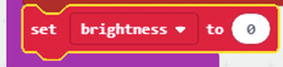
| Place the set brightness to block into the on start block. |
4 |
| Place the set fadeAmount to block into the on start block after the set brightness to block. Then replace the number 0 with 100. |
5 |
| Use the on pin P1 released block to build steps 6–19. |
6 |
| Place the analog write block into the on pin P1 released block. |
7 |
| Replace the number 1023 with the variable brightness. |
8 |
| Place a set brightness to block into the on pin P1 released block after the analog write block. |
9 |
| Replace the number 0 with the add block. |
10 |
| Replace the left number of the add block with the variable brightness and the right number of the add block with the variable fadeAmount. |
11 |
| Place an if-then block into the on pin P1 released block after the set brightness to block. |
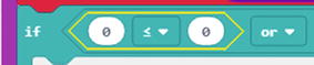
12 |
| Replace the true block of the if-then block with the logical or block. |
13 |
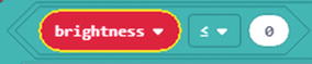
| Replace the left part of the or block with the less than block. |
14 |
| Replace the left number of the less than block with the variable brightness. |
15 |
| Replace the right part of the or block with the greater than or equal to block. |
16 |
| Replace the left number of the greater than or equal to block with the variable brightness. Replace the right number of the greater than or equal to block with 1023. |
17 |
| Place the set fadeAmount to block into the then part of the if-then block. |
18 |
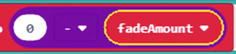
| Replace the 0 with a subtract block. |
19 |
| Replace the right number of the subtract block with the variable fadeAmount. |


Code for controlling the brightness of an LED by pressing a button
Now download and flash the code onto the micro:bit. After uploading completes, the code will start immediately to run. Initially, the blue LED won’t emit any light.
To fade the LED off and on, gradually increase your PWM value from 0 (all the way off) to 1023 (all the way on) and then back to 0 once again to complete the cycle. In the code you built, the PWM value is set using a variable called brightness . Each time you press and release button A, it increases by the value of the variable fadeAmount .
If brightness is at either extreme of its value (either 0 or 1023), then fadeAmount is changed to its negative. In other words, if fadeAmount is 100, then it is set to –100. If it's –100, then it's set to 100. The next time through the loop, this change causes brightness to change direction as well.

Code for controlling the brightness of an LED by pressing both buttons

Hardware setup for use in both buttons
3.2.5 Using the Push-Button Textile Element As a Button Counter
The Wearic push-button textile element can be used to do some action based on how many times the button is pushed. To do this, you need to know when the pushbutton changes state from off to on (or vice versa) and count how many times this change of state happens.
In this project, you learn how to count state changes of a pushbutton and display the result on the micro:bit 5 × 5 LED matrix.

Connecting the push-button element with the micro:bit pin 0
Step-by-step instructions to build the code
Step | Blocks | Description |
|---|---|---|
1 |
| Use the on start block to build steps 2–4. |
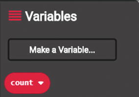
2 |
| Create a variable named count. |
3 |
| Place the set count to block into the on start block. |
4 |
| Replace 0 with 1. |
5 |
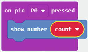
| Place the on pin P0 pressed block onto the workspace to build steps 6–8. |
6 |
| Place the show number block into the on pin P0 pressed block. |
7 |
| Replace 0 with the variable count. |
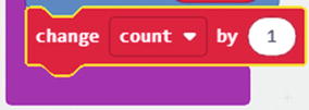
8 |
| Place the change count by 1 block into the on pin P0 pressed block. |


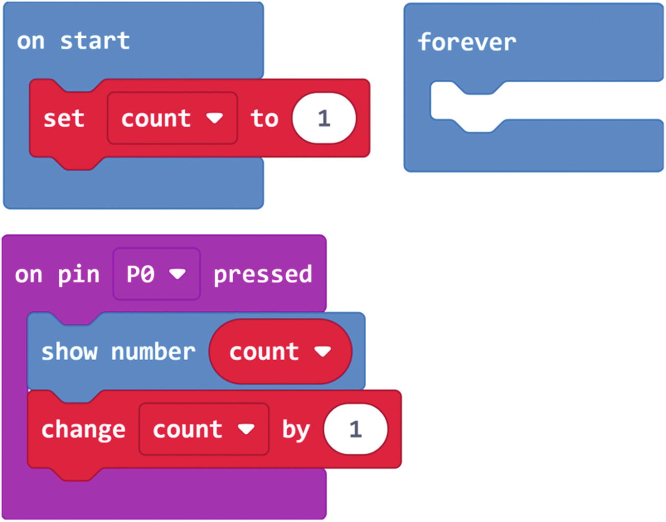
Code for counting the number of button presses
After building the code, download and flash it onto the micro:bit. After uploading completes, the code will start immediately to run. Now press and release push-button A on the textile push-button element. Each time the micro:bit 5 × 5 LED matrix will display the number of button presses so far.
The preceding code used the state from off to on to detect a button press. If you want to use on to off state, just replace the on pin P0 pressed with the on pin P0 released block.
3.3 Technical Specifications
Technical specifications of the push-button textile element
Size | 120 × 50 mm |
Digital input | 2 pushbuttons |
Voltage supply | 5 V DC |
Max. current | 100 mA DC |
Textile material | Polyester, silver yarn |
Debounce circuit | Low pass |
Washability | Limited washability |
Do not use higher current than 100 mA DC and voltage over 5 V.
3.4 Summary
In this chapter, you learned many techniques on how to use buttons on the push-button textile element with your wearable projects. You learned to build code with the MakeCode for each problem as well.
In the next chapter, you will learn how to use the textile heating element for your wearable projects and how to code the textile heating element with the MakeCode blocks.