
In this chapter, you will learn about how to use the Wearic textile wetness sensor to detect if your garments got wet by liquids such as water and ice.
6.1 Wearic Wetness Sensor
The Wearic wetness sensor can detect small amounts of water or other liquids and ice on its substrate. The most common measurement principle for textile wetness sensors is a resistance measurement between two conductive electrodes. The support fabric on which the electrodes are built is an insulating material (e.g., polyester, cotton, polypropylene).
In the “dry” state, the textile wetness sensor has a very low electrical conductivity. In other words, the resistance is very high at about 1 megaohm. In a “wet” state, the ionic conduction starts, and the resistance changes to 1 kiloohm which leads to high electrical conductivity.
A big advantage of textile sensors is that fabrics absorb and spread liquids very well. Therefore, a small amount of liquid can change the resistance to a large amount. Also, the design of the two electrodes influences very strongly how big the shift is. The smaller the space between the electrodes, the more sensitive the sensor. To minimize noise, it is useful to define a resistance area and adjust a voltage divider for the desired measuring area.

Wearic wetness sensor
These sensors are easy to use, but they’re rarely accurate. The output may vary from sensor to sensor. So basically, when you use textile wetness sensors, you should only expect to get ranges of response. While textile wetness sensors can detect moisture or amount of liquids, they’re a bad choice for detecting the exact number of volume on them. However, for most wetness- and moisture-detecting wearable applications, they’re a good choice.
6.2 Testing Your Wetness Sensor
First, measure the resistance of the “dry” textile wetness sensor.
Then measure the resistance by spraying (you can use a water spray bottle for this) a very small amount of water onto the sensitive area of the textile wetness sensor.
Finally, measure the resistance by spraying a large amount of water onto the sensitive area of the textile wetness sensor (to make it completely wet).
Try different ranges with your multimeter, between 20 MΩ and 2 kΩ. Because the resistance changes a lot, if you have a multimeter that supports auto-ranging mode at hand, turn it on because an auto-ranging multimeter works well here.
You can perform another experiment using ice. But remember to completely dry your textile wetness sensor before getting started.
6.3 Reading Wetness Sensor Values

Hardware setup to measure the wetness. Color code for the 10 kΩ resistor – brown, black, orange, gold
- 1.
Connect one of the snaps on the wetness sensor to the micro:bit pin 1.
- 2.
Connect the remaining snap on the wetness sensor to the micro:bit 3V.
- 3.
Connect the 10 kΩ resistor between micro:bit pins 1 and GND.
Now you are going to build a code to display the sensor values generated by the textile wetness sensor. The sensor values change rapidly when you pour water or some liquids onto the surface of the textile wetness sensor. It is not wise to use the micro:bit 5 × 5 LED matrix to display the sensor values – your micro:bit usually scrolls text and numbers, and it will take some time to display the entire value, so you may miss many sensor readings during the time.
As a solution, you will be writing data on the micro:bit’s serial output so you can read them from your computer (as long as your micro:bit is connected to your computer with a USB cable).
Step-by-step instructions to build the code
Step | MakeCode Blocks | Description |
|---|---|---|
1 |
| Use the forever block. This will repeat everything you place into it. |
2 |
| Place the serial write number block into the forever block. |
3 |
| Replace the number 0 with the analog read pin block. |
4 |
| Choose P1 from the drop-down menu. |
5 |
| Place the serial write line block into the forever block after the serial write number block. |


Code for writing data on the serial port
After you complete the code, download and flash it onto the micro:bit. The code will start to run immediately, but you can’t see any output on the micro:bit display. To get the values, you should read the micro:bit’s serial port.
- 1.
After downloading or installing, start the PuTTY.
- 2.
Use the following settings: COM9, 115200, Serial. Replace COM9 with the correct COM port number which has been assigned to your micro:bit (Figure 6-4).
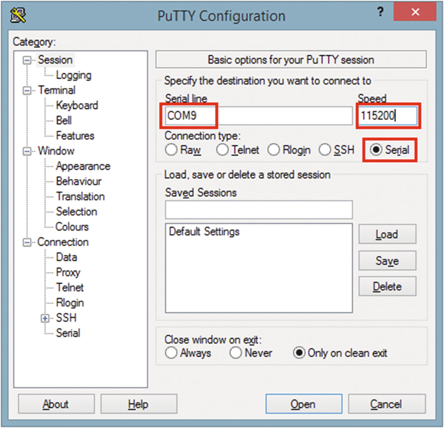
Configuration settings for the Session
- 3.
In the Terminal section, check Implicit CR in every LF (Figure 6-5).

Configuration settings for the Terminal
- 4.
Finally, click Open.
- 5.
The serial terminal will open, and the wetness sensor values will display on it (Figure 6-6).

PuTTY terminal output, without pouring water/placing ice onto the textile wetness sensor
- 6.
If you haven’t poured water or added ice yet onto the textile wetness sensor, the sensor reading you will get should be at about 9.
- 7.
Now pour water onto the textile wetness sensor. First, start with a small amount of water and then increase the amount of water to make the sensor fully wet. You can see the sensor values increase to around 370 (the maximum you can get is 1023, but you can’t practically reach this point) (Figure 6-7).
Note Not all the Wearic textile wetness sensors produce the same value for the same amount of water. Your textile wetness sensor may produce a different range of values than the values shown in this book.

PuTTY terminal output after pouring a large amount of water onto the textile wetness sensor
This experiment lets you determine the approximate values for different amounts of water and ice (or you can experiment with other liquids too).
6.3.1 Read the Serial Output in Mac OS
- 1.
Connect the micro:bit to your computer.
- 2.
Open a terminal window.
- 3.
Type ls /dev/cu.* and press the Enter key on the keyboard.
- 4.
Type screen /dev/cu.usbmodem1422 115200 and press the Enter key on the keyboard.
- 5.
To exit, press Ctrl-A followed by Ctrl-D.
6.4 Displaying Different Wetness Levels
Wetness levels and analog read values
Values | Wetness Level |
|---|---|
0–9 | Dry |
10–150 | Slightly wet |
151–250 | Medium wet |
251–1023 | Fully wet |
There is no technical rule or mathematical model to determine the value range for each wetness level. You can use different value ranges for each wetness level based on your requirement – but remember not to overlap values.
Now let’s build the code to display the wetness levels on the PuTTY terminal when you apply different amounts of liquid onto the textile wetness sensor. You can use the same soft circuit you built in the previous section (the wetness sensor should be connected to the micro:bit pin 1).
Step-by-step instructions to build the code
Step | MakeCode Blocks | Description |
|---|---|---|
1 |
| Use the forever block. This will repeat everything you place into it. |
2 |
| Create a variable named wetness. |
3 |
| Place the set wetness to block into the forever block. |
4 |
| Replace the number 0 with the analog read pin block. |
5 |
| Choose P1 from the drop-down menu. |
6 |
| Place an if-then-else block into the forever block after the set wetness to block. |
7 |
| Click two times the plus button to add two more else-if sections. |
8 |
| Replace the true block with the less than block. |
9 |
| Replace the first input with the variable block, wetness. Also, replace the second input with the value 10. |
10 |
| Place a serial write line block into the “first” then part. Then type in dry. |
11 |
| Duplicate the less than block two times and place them into the placeholders of each of the else-if sections. |
12 |
| In the “first” else-if section, in the less than block, replace the first input with the variable block wetness. Also, replace the second input with the value 151. |
13 |
| Place a serial write line block into the “second” then part. Then type in slightly wet. |
14 |
| In the “second” else-if section, in the less than block, replace the first input with the variable block, wetness. Also, replace the second input with the value 251. |
15 |
| Place a serial write line block into the “third” then part. Then type in medium wet. |
16 |
| Place a serial write line block into the else part. Then type in fully wet. |


Code for detecting wetness levels
After you complete the code, download and flash it onto the micro:bit. After flashing, open your micro:bit’s serial port and connect to it using the PuTTY serial terminal emulator. Follow the same steps explained in the previous section to open the serial port. You can use the same serial port unless you have connected any USB devices with your computer after the previous project. However, check your micro:bit’s serial port again with the Device Manager.
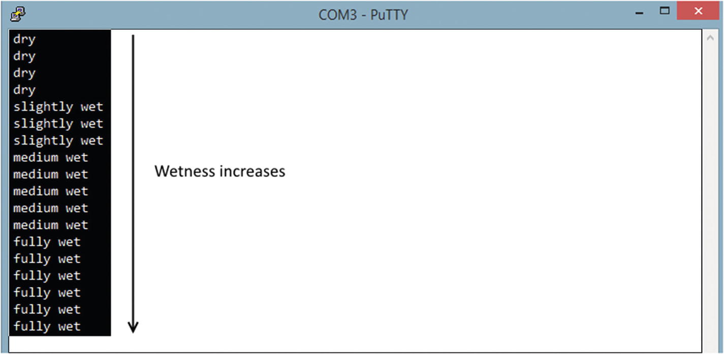
PuTTY terminal output when pouring water onto the textile wetness sensor
6.5 A Real-World Use Case
Most of the wetness detectors commercially available in the market use the preceding technique to detect liquids on their surface. For example, The TEXIBLE Wisbi bed insert (Figure 6-10) detects wetness for people who suffer from urinary incontinence. If wetness from the bed is detected, a notification is automatically sent to the app or the recipient. A delay can also be set as required.
You can read more about the TEXIBLE Wisbi by visiting its product page at www.texible.at/shop/texible-wisbi-pflegeset-classic-betteinlage-sender-steckdoenempfaenger/.

TEXIBLE Wisbi Plus – care set (bed insert, transmitter, socket receiver). Image courtesy of TEXIBLE GmbH (https://texible.com/)
6.6 Technical Specifications
Technical specifications of the textile wetness sensor
Size | 180 × 90 mm |
Thickness | 1.25 mm |
Connectors | 2 snaps (15 mm s-spring) |
Sensing area | 100 × 100 mm |
Resistance range | 1 kΩ–1 MΩ |
Liquid amount | 0.5–10 ml |
Textile material | Cotton, stainless steel yarn |
Measurement circuit | Voltage divider |
Washability | Limited washability |
6.7 Summary
In this chapter, you learned how to use the Wearic textile wetness sensor with the micro:bit to detect various wetness levels. In the next chapter, you will learn how to send the textile sensor data to a smartphone (or tablet) using Bluetooth Low Energy.