
2
Antennas
The antenna transmits and receives the radio waves which Bluetooth wireless technology uses to communicate, so it is a crucial part of any Bluetooth implementation. At their crudest, 2.4 GHz antennas can be simple lengths of wire, but for the best performance and to fit well with a product’s form factor, more sophisticated antenna designs are required.
When choosing and positioning antennas, the surrounding environment has to be taken into account, as this can have marked effects on antenna performance.
2.1 Radiation Pattern
Antenna radiation patterns are usually plotted in two dimensions: azimuth and elevation. The azimuth pattern is the pattern of radiation looking down on the antenna from above. The elevation pattern is the pattern of radiation looking at the antenna from the side.
A dipole antenna radiates in a torus (a doughnut shape). Figure 2–1 shows the radiation patterns this gives. At the left is the azimuth pattern; the radiation is a perfect circle with the same strength in all directions. At the right is the elevation pattern; at the sides of the antenna, the radiation is strong, dropping away to nothing above and below the antenna.
Figure 2–1 Azimuth and elevation patterns for a dipole antenna
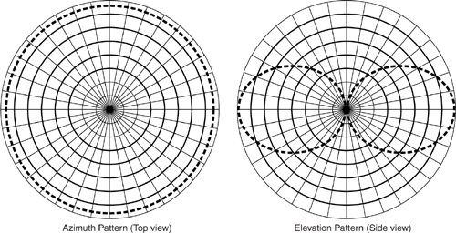
The radiation pattern of an antenna is useful in designing Bluetooth products because it tells you what the signal strength will look like from different angles to the product. In the example of a dipole aerial given above, the antenna works best if it is at 90 degrees to the path leading to the device it is communicating with. So if devices are spaced out horizontally, dipoles work best if they are kept vertical. On the other hand, there is still good signal strength at up to a 45 degree angle, so the product could be held at an angle and the aerial would still work; or, products could be spaced out with say a laptop on a desk and a cellular phone under the desk, and there would still be a good chance of the two devices getting a good enough signal to connect.
Some antennas have very directional radiation patterns, and others are closer to isotropic (a spherical pattern the same in every direction). The ability of an antenna to concentrate radiation in a particular direction is known as its directive gain.
The desired pattern will vary according to the type of product an antenna is being built into. LAN access points may wish to cover a room and have directional coverage which can be targeted into the room. This is possible for a LAN Access Point, as its antenna can be aimed when it is installed. Conversely, handheld devices such as cellular phones generally need to transmit and receive over a wide range of angles, so you definitely do not want strongly directive gain patterns. When choosing an antenna for a product, the desired radiation pattern suitable for its usage and positioning should be taken into account.
Finally, the orientation of the electromagnetic waves may be taken into account. This is known as the polarisation. Polarisation has linear and circular elements. For the best performance, transmit and receive antennas are matched for polarisation. This is unlikely to be practical with Bluetooth systems, as such a wide variety of devices will be operating at such a wide variety of angles. A combination of antenna radiation patterns and polarisation effects could lead to devices performing better when held at different angles. Ideally the user should not be aware of these effects, and Bluetooth should appear to be a completely directionless system.
2.2 Gains And Losses
The gain of an antenna is the ratio of power in to power out. Usually antenna gain is measured in dBi; this is gain relative to an isotropic antenna (an antenna which radiates the same in all directions in a perfect sphere and has a gain of one, so power out = power in).
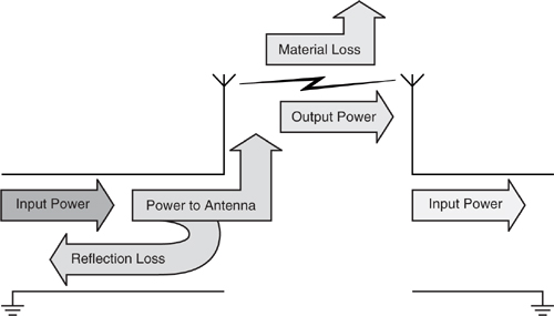
Severe losses can occur if the feed between the radio and the antenna is not well matched, as the signal will be reflected back down the feeder. Further losses are experienced in the antenna itself, and then there are material losses due to the signal being absorbed in the propagation medium.
In the case of microwave transmissions, water is a strong absorber, so signals which have to pass through flesh (mostly water) will suffer high material losses. Losses will also occur through furniture, and metals will block the signal.
Figure 2–2 illustrates the losses in getting a signal from the radio transmitter through to the receive antenna.
Figure 2–2 Losses in transmitting through an antenna
Of course, the material losses in the propagation path will include the casing of the Bluetooth module. Products such as laptop computers are typically manufactured with metal screening around the internal components. The metal screen is designed to contain radio signals, so a Bluetooth antenna could not be placed inside such a screen. This is the reason why Bluetooth PCMCIA cards have bulges protruding outside the laptop; these contain the antenna.
Most plastics do not absorb significantly in the ISM band, so plastic casings should not cause significant material losses for Bluetooth systems.
2.3 Types Of Antennas
The most popular antenna types for Bluetooth devices are dipole, flat panel, and microstrip. Other antenna types are possible in the ISM band, such as multiple element dipoles, Yagis, parabolic dishes, and slotted antennas. However, the more complex antennas are less likely to have uses in Bluetooth systems. This is because of cost, form factor, or because their radiation patterns are strongly directional, which tends not to suit Blue-tooth applications.
2.3.1 Dipole Antennas
Dipole antennas are cylinders, with the signal usually feeding in from the bottom. Very simple dipole antennas are often made out of short sections of coaxial cable for development purposes.
As the elevation patterns in Figure 2–1 showed, a dipole antenna transmits best from the side of the antenna. Usually it is fed from the base of the antenna, but it can also be fed from the centre of one side.
The length of a dipole antenna must be related to the wavelength of the signal it is carrying. Half wave and quarter wave dipoles are commonly used.
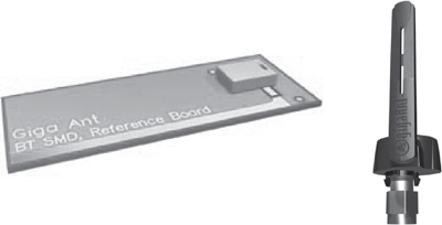
Dipole antennas are available in various form factors. Figure 2–3 illustrates the variety available with a snap in surface mounted package at the left, and a swivel antenna with SMA connector at the right. Both are half wave dipole antennas.
Figure 2–3 Two types of dipole antenna package (pictures supplied by Giga-Ant).
2.3.2 Flat Panel
Flat panel antennas are small metal patches, and are usually square or rectangular. They are strongly directional, so their radiation pattern is not ideal for handheld devices. On the other hand, they can be made very small for the ISM band and can be mounted directly onto PCBs, both of which help to reduce costs.
A popular form of flat panel antenna used in Bluetooth devices is a PIFA (Planar Inverted F Antenna). This antenna is named for its resemblance to a capital F on its side. It has a flat panel as far away from the ground as possible and is fed by two contacts which form the arms of the F (see Figure 2–4).
Figure 2–4 PIFA antenna structure.
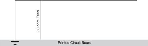
A PIFA antenna can also be fabricated as a microstrip antenna using tracks on a Printed Circuit Board, or PCB (see next section).
2.3.3 Microstrip
Microstrip antennas are simply patterns on PCBs. The fact that tracks on a PCB can be made into a useful antenna illustrates the care that designers must take in product design if they are not to inadvertently produce radiating components where they don’t want them!
The radio module of the Ericsson Bluetooth Developer’s Kit comes with a microstrip antenna, which is implemented as a printed pattern on a small PCB.
2.4 Ceramic Antennas
Ceramic antennas can take advantage of phyiscal properties of specialised ceramic materials, such as high permittivity, to produce miniaturised antennas.
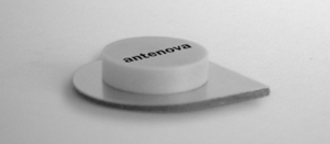
Recent developments in ceramic antenna technology are adding functionality and improving performance of antennas. For instance, it is now possible to construct a ceramic antenna which is highly efficient and can be made both directional and steerable (see Figure 2–5). Many antennas are highly affected by their surroundings and perform poorly when placed close to one another, these new antennas experience less proximity effects.
Figure 2–5 High efficiency ceramic antenna (courtesy of Antenova>
2.5 On-Chip Antennas
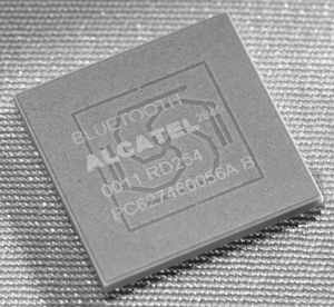
For the ultimate in integration, an on-chip antenna is a possibility. At the time of writing, at least one supplier has announced a Bluetooth baseband and radio chip with an on board antenna (see Figure 2–6). The antenna is implemented as a four armed, spiral microstrip on the top surface of the Bluetooth chip’s ceramic package. An RF filter is also printed on the top of the package to improve the characteristics of the device’s transceiver.
Figure 2–6 Bluetooth chip with on-chip antenna (courtesy of Alcatel Micro Electronics).
The cost and space savings of such antennas are obvious; however, because the radio signal is blocked by the chip beneath it, the on chip antenna can only radiate in a hemisphere on one side of the chip.
This might be seen as an advantage for some products such as headsets, where health concerns have been expressed. Users may be able to put up with the inconvenience of only being able to connect to devices on one side of their body for the sake of the assurance that radiation levels will be reduced yet further below the already low levels of Blue-tooth. However, there are some products which will require more complete coverage; therefore, even a device with an on board antenna will typically provide for the alternative of connecting an external antenna.
2.6 Antenna Placement
The characteristics of an antenna are strongly affected by the surrounding ground planes. Shielding from casings and components also affects antenna radiation patterns, and of course, the feed to the antenna affects reflection losses. The combination of these factors means that for optimum radio performance, it is crucial to take the antenna into account when designing PCBs for microwave devices.
2.7 SUMMARY
Handheld Bluetooth devices require antennas which radiate in a pattern as close to a sphere as possible, so that they can connect in any direction, at any angle. For devices such as LAN access points, a more directional antenna could be beneficial so that coverage could be restricted to a single room.
Different antenna types will radiate in different patterns, so the type of product may affect the antenna choice. The available space and the cost of different types of antennas will also affect the choice of antenna for a product.
Surrounding components and casings can affect the performance of an antenna as well. In particular, the feed and proximity of ground planes can affect an antenna’s characteristics.
Thus, the positioning and characteristics of the antenna must be considered when designing Bluetooth products.