
7
The Link Manager
The host drives a Bluetooth device through Host Controller Interface (HCI) commands, but it is the Link Manager (LM) that translates those commands into operations at the baseband level, managing the following operations.
- Attaching Slaves to a piconet and allocating their active member addresses.
- Breaking connections to detach Slaves from a piconet.
- Configuring the link including controlling Master/Slave switches (where both devices must simultaneously change roles).
- Establishing ACL (data) and SCO (voice) links.
- Putting connections into low-power modes: Hold, Sniff, and Park.
- Controlling test modes.
A Bluetooth Link Manager communicates with Link Managers on other Bluetooth devices using the Link Management Protocol (LMP).
The Bluetooth specification merely defines the LMP messages exchanged between Link managers; it does not go into any details as to how the protocol’s instructions are carried out. However, given the content of the messages, one can draw sensible conclusions about what the Link manager does: It controls piconet management (establishes and destructs links), link configuration, and security functions.
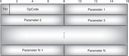
Figure 7–1 LMP PDU payload body.
Some LMP messages require responses, others do not. If a Link Manager receives a message which is disallowed on a link and the message requires a response, then it responds with an LMP_not_accepted message using a reason code of “PDU not allowed”, otherwise the PDU should be ignored.
7.1 Lmp Protocol Data Units (Pdus)
Link Managers communicate with their peers on other devices using the Link Management Protocol. This defines a set of messages which are passed between Link Managers.
Every LMP message (see Figure 7-1) begins with a single bit transaction identifier (TID), which is 0 if a Master initiated the transaction and 1 if a Slave initiated the transaction. A transaction can extend across several LMP exchanges, for instance all the exchanges required to set up pairing, including mutual authentication after link key creation form a single transaction, so all use the transaction ID from the first LMP_in_rand.
The transaction ID is followed by a 7 bit Operation Code (OpCode), which identifies the type of LMP message being sent. The OpCode is followed by the message’s parameters, each of which occupies an integral number of bytes (except for unpark messages, which are not byte-aligned to make them as short as possible).
7.2 The Link Management Channel
LMP PDUs are passed as single slot packets on the link management logical channel, (see section 4.8 for more details on Logical Channels). This channel is identified by setting the logical channel field in the packet header to 11.
The Link Manager sends its messages to the Link Controller for transmission. The Link Controller only guarantees to communicate on a link once every Tpoll slots, so there may be a significant time lag between the Link Manager sending a message to the Link Controller and the message being transmitted on air. The Link Manager has to be aware of this potential for delayed transmission, as it can affect the timing of transactions such as master slave switch, and starting hold mode.
Because flow control is intended to stop L2CAP data packets from being transferred, it is not used for LMP, so the flow bit on LMP PDU packets is always left as 0 by the transmitting device. In any case, its value doesn’t matter. As for LMP packets, the flow bit is ignored by the receiving device!
Now that we have seen how LMP PDUs can be sent and received by the lower layers, let’s look in more detail about what can be accomplished by sending LMP messages.
7.3 Link Setup
The Link Manager is responsible for setting up and managing the baseband connections that link Bluetooth devices. The Link Manager establishes ACL links by controlling the baseband; then LMP messages can be used to establish a SCO (voice) link across an existing ACL connection.
The Link Manager maintains data on Slaves to which it has allocated an Active Member Address (AM_Addr).
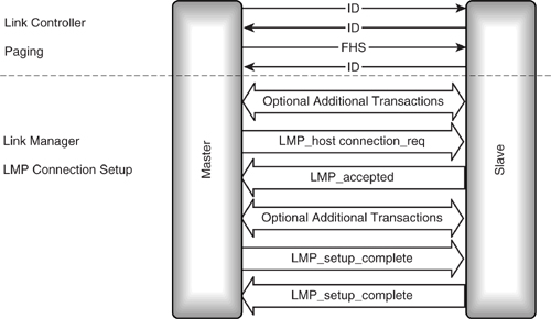
Figure 7-2 shows the messages involved in setting up an ACL connection. The Link Controller layer must establish a link between devices before LMP messages can be exchanged.
In between the Link Controller setting up a connection and the Link Manager sending the LMP_host_connection_req, optionally a limited set of messages can be sent. For version 1.1 of the Bluetooth specification these optional messages are:
- LMP_clkoffset_req.
- LMP_name_req.
- LMP_detach.
- LMP_version_req.
The first three of these messages can be used to temporarily connect to a device, retrieve its name and clock offset, and then detach before the host is informed of the link. The clock offset message is a useful part of this sequence because it allows a Master to speed up paging the next time it makes a connection by predicting where on its hopping sequence a potential Slave will be scanning.
The LMP_version_req is provided because some details of LMP messages and timeouts change between versions, so it is useful to find out as soon as possible which version of Link Manager is at the remote end of a connection.
Figure 7–2 LMP message sequence chart for ACL link setup.
LMP has a 30-second timout between a message being sent and its response being received. If this timeout is exceeded, the link is assumed to be dead. Before version 1.1 there were problems with the initial setup of a link because there was no timer running before LMP traffic started. This meant that if a Link Manager did not start correctly, there was no way to detect this and shut down the link. Version 1.1 solved this problem by specifying that the 30-second LMP response timeout should apply to the time between a Link control level connection being established and the LMP_host_connection_req being sent.
The LMP_setup_complete message is generated independantly by both Master and Slave when each is satisfied with the state of the link. This means that it is not obvious how the LMP_response_timeout should be applied to the LMP_setup_complete message, but a timeout is needed as there must be a way to shut down a link if the remote Link Manager never sends the LMP_setup_complete message. Version 1.1 specified that the LMP_setup_complete message should be sent before the LMP response timeout from the previous transaction has timed out. This means that if a series of transactions are carried out before sending LMP_setup_complete, then each transaction must start before the LMP_response_timeout of the previous transaction has expired.
Another possible source of confusion in the LMP_setup_complete message is the transaction ID. Because each Link Manager decides independantly when to send the message, each LMP_setup_complete counts as a separate transaction and carries its own transaction identifier. This was not obvious in version 1.0B of the Bluetooth specification, so version 1.1 specified explicitly that when the Master sends the LMP_setup_complete message it sets the transaction ID to 0, and when the Slave sends the message it sets the transaction ID to1.
Once an ACL link has been established, either the Master or Slave can request a SCO link setup across the ACL link. Both Master and Slave use an LMP SCO request to initiate a SCO connection setup as shown in Figure 7–3.
Figure 7–3 LMP message sequence charts for SCO connection setup.
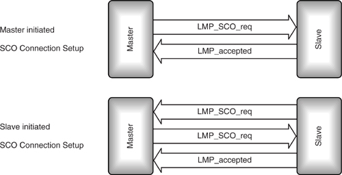
When the Master requests a SCO link, it sends an LMP_SCO_req containing the parameters for the link. SCO link parameters are:
- SCO handle.
- Timing control flags (used to request a timing change on an established link).
- DSCO—The SCO dedf2delay which indicates when the first SCO slot will happen.
- TSCO—The SCO interval which separates SCO slots.
- SCO packet type to use: HV1, HV2, HV3, DV.
- Air mode coding: μ-law, A-law, CVSD.
The Slave simply replies with LMP_accepted (or LMP_not_accepted).
A Master may have SCO links to several Slaves at once. Once a Master has set up one SCO link, it has limited freedom to assign other slots. Therefore, it makes sense to let Masters choose the timing parameters for SCO links. Typically, a Master will manage links to many Slaves, so the Master chooses connection handles. If a Slave chose a handle, it might pick one that the Master was already using on another link. So, when a Slave sends an LMP_SCO request, the timing parameters are not valid, and the handle is invalid and left at 0. If the Master is willing to set up a SCO link, it replies with
an LMP_SCO_req with valid parameters, and the Slave acknowledges with LMP_accepted, just as if the Master had initiated the transaction. (Of course, if the Master is not willing to set up a SCO link, it can reply to the Slave’s request with LMP_not_accepted.)
7.4 Lmp Link Shutdown
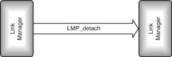
Any time that a Master or a Slave wishes to shut down a Bluetooth link, it sends an LMP_detach command as shown in Figure 7–4. A reason for the detach is included in the command; possible reasons are:
Figure 7–4 LMP message sequence chart for LMP_detach.
- User ended connection.
- Low resources.
- About to power off.
When a Slave has been detached from a piconet, the Master can reuse the slave’s active member address (AM_ADDR) to identify a new slave. If a slave did not detach correctly, there could be problems with two slaves trying to respond to the same AM_ADDR. Thus there is a detach procedure used by the Link Manager initiating the detach to ensure that a slave is fully detached before its address is reused:
- The LM initiating the detach finishes sending the current ACL packet with L2CAP data.
- The LM initiating the detach stops sending L2CAP data (obviously it makes no sense to send data to a device which is being detached!).
- The LM initiating the detach queues an LMP_detach for transmission and starts a timer of 6*Tpoll slots (Tpoll is the poll interval for the connection).
- If the 6*Tpoll timer expires before a baseband acknowledgement of the LMP_detach is received, the link is dropped and a link supervision timeout is started. If a baseband acknowledgement is received, a timer of 3*Tpoll slots is started.
- When the second timer (link supervision or 3*Tpoll) expires, then the AM_ADDR can be reused.
A timer is also used on the receiving side: If a Master receives an LMP_detach message, it starts a timer of 6*Tpoll slots; if a Slave receives an LMP_detach message, it starts a timer of 3*Tpoll slots. When this timer expires, the link can be dropped and the AM_ADDR from the link can be reused.
If the LMP_detach message is lost due to interference or devices moving out of range, then a link supervision timeout will occur and eventually the link will be detached anyway.
7.5 Role Change
Normally, the device which pages becomes the Master of a piconet, and the device which page scans becomes the Slave. The Slave can only transmit in reply to a transmission from the Master (except for reserved SCO slots). The Master also sets packet sizes, SCO intervals, and timing. All this means that the Master controls the bandwidth available to the Slave.
In some cases, the roles in which Master and Slave find themselves are not appropriate. They could shut down the link and set it up again with the former Slave paging and the former Master page scanning, but this is quite a time-consuming procedure, and of course, during the time the link is being re-established, no data can be transferred. To avoid this waste of time, LMP provides a means for the Master and Slave to switch roles (see Figure 7–5).
Figure 7–5 LMP message sequence chart for role change.
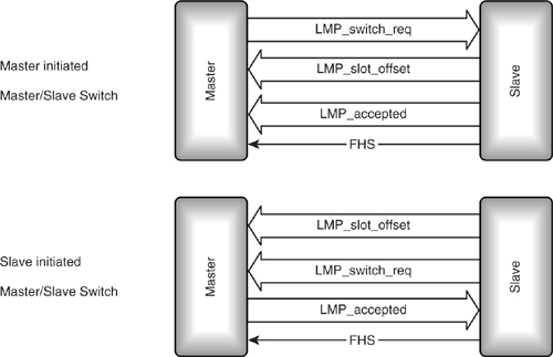
The device wishing to initiate a role change simply sends an LMP_switch_req. In version 1.1 a switch instant parameter was added to the LMP_switch_req to specify exactly when the Master/Slave switch should happen (in previous versions of the Bluetooth specification the message has no parameters.) Some implementations cannot react quickly to switch requests. To ensure that enough time is allowed, the switch instant must be 2*Tpoll or 32 slots after the switch request (whichever is greater).
If the Master sends the LMP_switch_req, the Slave responds with an LMP _slot_offset message. If the Slave initiated the switch by sending the LMP_switch_req, then it follows up by sending an LMP_slot_offset.
The LMP_slot_offset message contains a BD_ADDR and a slot offset. The BD_ADDR is the address of the Slave which is going to become Master after the switch. The slot offset is worked out by calculating the value in microseconds of the start of a TX slot if the Slave were Master of a piconet, then the value in microseconds of the start of the current Master’s transmit slot is subtracted. If the result is greater than 1250, a modulo 1250 operation is used to make the value between 0 and 1249. So if the time a transmit slot starts on the current piconet is TXstartslave’s clock, and the time a transmit slot would start if the slave were master is TXstartmaster’s clock, the the offset is given by the equation:
offset = (TXstartslave’s clock – TXstart master’s clock) mod 250
During the Master/Slave switch, an FHS packet is used to synchronise the two devices. The 1.25 ms accuracy of an FHS packet is not sufficient to allow the two devices to synchronise, so the device which starts as Slave uses an LMP_slot_offset message to send the difference between its clock and the other device’s clock. If the Slave requests the switch, it sends this message before the LMP_switch_req. If the Master requests the switch, the Slave sends LMP_slot_offset before the LMP_accepted message.
If the role change is accepted, the Slave must take over as Master. This means that the Master must synchronise to the Slave’s Bluetooth clock. Whichever side initiates the switch, the Slave sends the Master an FHS packet to enable the Master to synchronise to its clock. After the FHS packet has been acknowledged, both devices switch to the new timing.
It is important to note that Bluetooth version 1.0 does not define a mechanism for a Master with many Slaves to pass information from one Slave’s FHS packet on to its other Slaves. This means that a Slave cannot acquire the Master’s other Slaves.
Figure 7–6 shows what happens to a Master with three Slaves when it accepts a Master/Slave switch from one Slave. The Master’s single piconet splits into two piconets, joined in a scatternet by the former Master. The former Master (device A in Figure 7–6) now has a dual role as Master of the Slaves which have not switched role and Slave of the other device which switched roles.
Figure 7–6 Piconet configuration before and after Master/Slave switch.
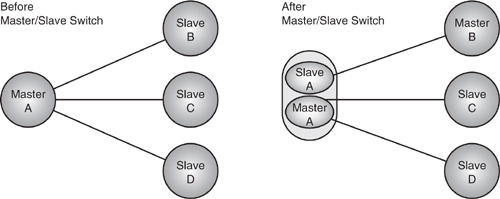
If device A in Figure 7–6 did not support scatternets or did not have sufficient resources to be present on two piconets, it could choose to either refuse the Master/Slave switch or disconnect Slaves D and C, which it would not be able to support after the switch.
For more information on Master/Slave switch procedures, see Chapter 5.
7.6 Control Of Multi-Slot Packets
When a link is first set up, it uses single-slot packets by default. Multi-slot packets make more efficient use of bandwidth, but there are circumstances in which they shouldn’t be used:
- On noisy links, multi-slot packets are more likely to be corrupted by a burst of interference.
- SCO links may not leave sufficient space between their slots for multi-slot packets.
Prior to version 1.1 because Masters often had links to several Slaves, it was the Master which usually had the tightest constraints on available slots, so the Master chose the packet types used on a link. The procedure was as follows:
The Master imposed a maximum packet size on the Slave by sending an LMP_max_slot command (see Figure 7–7). The Slave could not refuse, so there was no need for an LMP_accepted reply (the baseband acknowledgement scheme ensured that the LMP message is reliably transmitted). If the Slave wished to change the maximum packet size, it sent the Master an LMP_max_slot_req. If the Master was willing to allow the Slave to use this packet size, it replied with an LMP_accepted; otherwise, it sent an LMP_not_accepted and the Slave had to stick to the previous maximum packet size.
Figure 7–7 LMP message sequence chart for control of multi-slot packets.
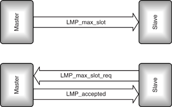
The system of allowing the Master to dictate packet sizes caused problems for Slaves which could not handle multi-slot packets (for example because they had tight time constraints imposed by scatternet operation), so version 1.1 changed the procedures to allow slaves to take a greater part in negotiation of packet types. The default for any new connection is now set to single slot packets only (this includes connections formed by Slaves returning from park mode, or connections formed after a Master/Slave switch). A device can signal that it wants to receive a different set of packet types by sending an LMP_max_slot message. If it wants permission to transmit multi-slot packets, it sends an LMP_max_slot_req. If it receives an LMP_accepted in reply, it may then transmit multi-slot packets; if it receives an LMP_not_accpted in reply, it is restricted to the packet types already negotiated.
7.7 Security
The Bluetooth baseband includes an encryption key generation and cipher engine. For encryption and decryption, this engine must be configured and controlled by higher layers, and that control must be synchronised at both ends of the Bluetooth link. LMP provides the mechanism for negotiating encryption modes and coordinating encryption keys used by devices at either end of the link. For details of LMP’s security procedures, see Chapter 15.
7.8 Low-Power Modes
LMP supports control of low-power connection modes. In these modes, a Slave and Master remain synchronised, but can save power by leaving the connection dormant for defined periods. These modes and how LMP controls them are covered in detail in Chapter 16.
7.9 Power Control
The transmit power emitted by the radio should be kept to a minimum to extend battery life, as well as to minimise interference.
Battery life will be radically affected by the power used by the radio, as it is likely to be the main power drain in the system. As many Bluetooth devices will be part of small, portable devices, they will be powered by batteries, so keeping power low to extend battery life is an important capability.
If Bluetooth piconets operate close to each other, their radio transmissions will tend to interfere. The lower the power, the less interference there will be with adjacent piconets, so using minimal power allows more piconets to exist in a given space.
Minimal power is important, but how does a Bluetooth device know what the minimum level is? Only the receiving device knows whether reception is good enough for power to be reduced, so Bluetooth allows the receiving device to request changes in the transmit power.
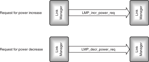
As Figure 7–8 shows, a device wishing to change power levels at the far end of the link simply sends an LMP_incr_power_req to increase power or an LMP_decr_power_req to decrease power. There is no need for an LMP_accepted response to these requests, because if the request is not received, the requesting device will detect that the power is still at the wrong value and reissue the request.
Figure 7–8 LMP message sequence charts for successfully changing power levels.
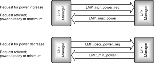
There are limits to the radio power allowed for Bluetooth devices, so eventually there comes a point where the power cannot be increased any more, no matter how bad reception is. Similarly, a radio can only have its power reduced by a limited amount before reducing power more turns it off. To avoid a device repeatedly making requests that the far end can’t satisfy, the LMP provides reply messages to tell a device requesting an increase in power when the power cannot be changed as requested. Figure 7–9 shows these messages. LMP_max_power is returned if a device requests an increase in power when power is at maximum; LMP_min_power is returned if a device requests a decrease in power when power is at minimum.
Figure 7–9 LMP message sequence charts for failing to change power levels.
7.10 Quality Of Service
LMP supports messages to configure the quality of service on a connection. It also supports messages which can set a channel to automatically change packet types according to the channel quality. So, data can be transferred at a higher rate when the channel quality is good, but a lower rate with more error protection can be used if the channel quality deteriorates. These messages are covered in detail in Chapter 17.
7.11 Information Messages
LMP provides a variety of messages to request information from the far end of the link. Some of the messages are used to retrieve information requested by a device’s host, and some are to retrieve information needed by the Link Manager itself.
7.12 Supported Features
Some of the features of the Bluetooth standard are optional. The LMP_features_req message is used to inquire about which features are supported, and the LMP_features_res message responds with the information.
For version 1.0, the optional features are:
- Multi-slot packets—both 3-slot packets and 5-slot packets are optional.
- Encryption.
- Low-power modes—Hold, Park, and Sniff are all optional.
- RSSI—this is useful to higher layers, but support is optional.
- Power control for low-power radios—power control is mandatory for radios over 1 mW (0 dBm).
- Channel-quality-driven data rate changes.
- SCO links and where SCO is supported—HV2 and HV3 packets are optional.
- Voice coding schemes—CVSD, log -law, and log A-law.
- Optional paging schemes.
- Timing accuracy message.
- Master/Slave switch and slot offset messages (a slot offset message is needed to switch roles).
Version 1.1 added some extra fields to the end of the features parameter:
- Transparent SCO data—this indicates whether data can be sent unchanged through a SCO channel, for instance, to transmit synchronous data bypassing the SCO codecs.
- Flow control lag the total amount of L2CAP data that can be sent following the receipt of a valid payload header with the payload header flow bit set to 0.
When the baseband receives an ACL packet with the flow bit set to zero, it should stop transmitting L2CAP data. However, in some implementations processing delays mean that some L2CAP data is sent after the zero flow bit has been received; this delay in implementing flow control is called flow control lag. For maximum efficiency, it is useful to know what the flow control lag at the other end of a link is. That way, a flow bit can be set to 0 when there are still enough buffers left to accommodate data sent during the flow control lag period. The flow control lag field allows this information to be passed. It is a 3-bit field and the unit for flow lag is 256 bytes (so, for example, 0b010 gives a flow lag of 512 bytes).
The supported features information can be used within the Link Manager; for example, if it knows the remote device does not support 5-slot packets, it can avoid wasting time trying to configure the connection for that type of packet. The information can also be passed to higher layers of the protocol stack through the HCI command HCI_Read_Remote_Supported_Features, so that the upper layers can also avoid wasting time trying to use unsupported features.
7.13 Lmp Version
The LMP_version_req is used to request version information from a Bluetooth device. The version information is returned in an LMP_version_res message.
Early versions of the Bluetooth standard used a different OpCode to identify the LMP_version_req, so developers cannot rely on this command to get version information on devices using LMP versions before release 0.8. This problem is confined to a few early releases of development kits and will not affect any consumer products. Any developer who suspects he or she may have an early version development kit can retrieve version information using the HCI command Read_Local_Version_Information. Many suppliers of development kits will be able to supply software to upgrade devices to later versions.
The version information which is supplied in the LMP_version_res is as follows:
- VersNr—The version of LMP supported.
- CompId—A company ID for the company which created the Link Manager implementation.
- SubVersNr—The developing company’s version number for the Link Manager implementation.
The version information can help track problems with LMP implementations, and can also be used to allow workarounds when connecting to implementations with known problems. Future versions of LMP will add new features, so the Bluetooth version number will be useful to identify, as a supplement to the LMP_features_req, the capabilities of an LMP implementation.
7.14 Name Request
Every Bluetooth device has a user-friendly name which can be up to 248 bytes long. LMP provides the LMP_name_req message to request a user-friendly name and the LMP_name_res message to respond with the name.
All LMP messages are carried in DM1 packets, and the data payload in a DM1 packet is only 17 bytes. One byte is used to identify the LMP message, so this only leaves 16 bytes, not enough to carry a 248 byte name!
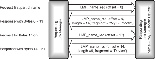
LMP solves this problem by using a series of messages to pass fragments of the user-friendly name. The LMP_name_req message has an offset parameter which identifies the first byte of the fragment it is requesting, and the LMP_name_res message has the same offset parameter. It is possible that the fragment of name requested might not completely fill the LMP_name_res message, so there is also a parameter in the response to give the length of the name fragment. With a byte used for the name offset and a byte used for the length of the name fragment, this leaves 14 bytes to carry the name fragment itself.
For example, if a host has a name “My Bluetooth Device,” the sequence of messages in Figure 7–10 is used to retrieve the name. In the first LMP_name_req, the name offset is 0, so the first 14 bytes of the name are retrieved. The requesting device keeps adding 14 to the offset until it has retrieved the whole name. In this case, the name fits into two responses, the second response has length 9 because a NULL byte (0x00) terminates the name.
Figure 7–10 LMP message sequence chart for passing a user friendly name.
In the example above, it is obvious that the second response has the last part of the name because the name fragment doesn’t fill the whole message. If the last part of the name filled the whole response message, the requesting device would send out another request with an offset that was past the end of the name. In this case, the responding link manager simply sends back an LMP_not_accepted with an error reason “Invalid LMP Parameters”.
7.15 Test Mode
Test modes are useful both for certification of Bluetooth devices by testing authorities and for a manufacturer’s production line testing of devices. LMP provides the LMP_test_activate message to put devices into a special test mode. Once a device is in a test mode, LMP_test_control messages can be used to start specific tests. Further details of LMP’s test control mechanism are given in Chapter 20.
7.16 Summary
Figure 7–11 summarises LMP operations. As you can see, there are many alternative paths through this diagram. The simplest route after the LC has finished with paging and page response is to just exchange messages to confirm connection setup is complete.
More complex routes can involve changing roles of Master and Slave, either after paging but before connection setup is complete or at any time thereafter. Similarly, the security procedure’s authentication, pairing, and encryption can be passed through on the way to connection setup-complete, or they can be visited at any time afterwards.
Figure 7–11 Summary of LMP operations.
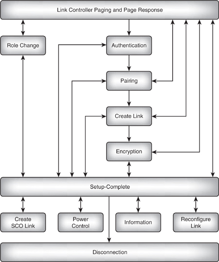
Once the connection has been set up, it can have up to three SCO connections created across it, or its mode can be changed either to a low power mode or test mode. The link can also be reconfigured at any time, including at mode changes, quality of service changes, packet type changes, and power level changes. Finally, information about an active link can be retrieved at any time.
When the connection is no longer required, LMP can cause disconnection.