
3
Radio
3.1 Introduction
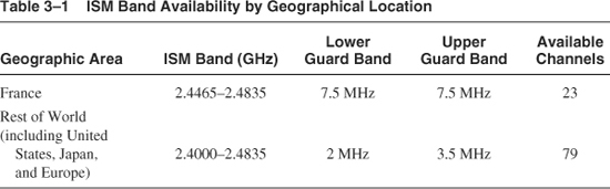
Bluetooth devices operate in the globally available, unlicensed ISM band situated at 2.4 GHz. This band is reserved for general use by Industrial, Scientific, and Medical (ISM) applications, which obey a basic set of power and spectral emission and interference specifications such as defined by the ETSI ETS 300-328 in Europe or the FCC CFR47 Part 15 in the United States. Although globally available, the ISM band has restrictions in some geographical locations. The SIG is actively lobbying regulatory bodies to harmonise these regulations worldwide and to date has had success with Japan and Spain and positive reactions from France. The situation at the time of publication is described in Table 3–1 and France is due to release the full ISM band in 2003. We will refer to the majority situation in this text.
Figure 3–1 System timing requirements.
The ISM band is occupied by a plethora of other RF emitters, ranging from wireless applications such as short range proprietary techniques (car security, cordless headphones, etc.) and standardised WLAN (Wireless Local Area Networking) applications (IEEE 802.11) to random noise generators such as microwave ovens and sodium vapour street lamps, which contribute significantly to the noise floor. As a result, the 2.4 GHz band is not a terribly stable or reliable medium. However, the band’s worldwide availability ensures widespread acceptance of Bluetooth. To cope with the hostile environment presented by the ISM band, Bluetooth specifically employs several techniques: frequency hopping, adaptive power control, and short data packets.
3.2 Frequency Hopping
Originally invented by the Austrian born actress Hedy Lamarr during World War II, the mechanism of frequency hopping has been used to great effect both as a means for secure communication and robust communication. Both attributes of the technique are important for Bluetooth. It is always possible for a radio channel to become temporarily blocked by an interference source, and as described above, this is quite likely in the busy ISM band. Although Bluetooth provides a retransmission scheme for lost data packets, it is altogether more efficient and robust to retransmit the data on a new channel, which is unlikely to also be blocked. Indeed, the algorithm employed to calculate the hop sequence ensures maximum distance between adjacent hop channels in the sequence. Also several active Bluetooth piconets may be within range of each other; with each piconet hopping independently with a pseudo random sequence based on each piconet’s identity/access code, collisions will be minimised. This is important as all Bluetooth devices only have 79 channels in which to operate. In an office or public environment, the number of active devices can very quickly reach this limit, and a low correlation between noncommunicating pairs is essential.
3.3 Modulation
The operating band of 83.5 MHz is divided into 1 MHz spaced channels, each signalling data at 1 M symbols per second so as to obtain the maximum available channel bandwidth. With the chosen modulation scheme of GFSK (Gaussian Frequency Shift Keying), this equates to 1 Mb/s. A binary 1 gives rise to a positive frequency deviation from the nominal carrier frequency, while a binary 0 gives rise to a negative frequency deviation.
To obtain the most efficient use of bandwidth while still maintaining acceptable error probability, the digital bit stream is modulated using GFSK with a BT product of 0.5 and a modulation index of between 0.28 and 0.35. The BT product is the product of adjacent signal frequency separation1 (0.5MHz) and symbol duration (1 μs). A BT product of 0.5 corresponds to the minimum carrier separation to ensure orthogonality (i.e., no cross-correlation) between signals in adjacent channels. The modulation index represents the strength of the peak frequency deviation (fd) and can be expressed as 2fdT, where T is the symbol duration. This translates to a frequency deviation range of 140 KHz to 175 KHz. The Bluetooth specification gives 115 KHz as an absolute minimum deviation.
1 The separation between modulation alphabet members or channel separation between modulated tones.
GFSK employs a Gaussian filter to smooth the frequency transitions so that the modulated carrier frequency changes smoothly with a Gaussian shaped envelope. This maintains continuous phase of the carrier frequency and reduces the emitted spectral side-lobes, allowing better spectral efficiency and less intersymbol interference. The Gaussian filter acts on the transmit bit stream and may be implemented in the radio as an analog filter, carried out in the digital part of the baseband using a FIR filter implemented as a Linear Feedback Shift Register (LFSR), or as part of a modulation lookup table.
3.4 Symbol Timing
The Bluetooth specification demands a symbol timing accuracy of ± 20 ppm. This means that the clock which is driving the baseband symbol processing logic must be accurate over all operating conditions and its operating life to this figure. With modern quartz crystal technology, this is not terribly demanding, and indeed, due to the easy availability of accurate 13 MHz references for GSM cellular phone applications, does not impose a large cost burden on a Bluetooth enabled product.
The result of this requirement is that over the longest transmitted packet—DH5—the worst case error in the phase of the last symbol as determined by the worst case receiver oscillator will be:
![]()
which is less than one-eighth of a symbol period. During the next reception, the symbol timing will be resynchronised. For this reason, very simple timing recovery schemes are possible for Bluetooth without necessarily needing to continuously track the on-air data burst.
3.5 Power Emission And Control
FCC regulations permit transmit power up to 0 dBm in the ISM band without spread spectrum operation. For high power emissions, a spread spectrum scheme must be adopted. Through the use of frequency hopping, Bluetooth is able to operate at up to 20 dBm, allowing a range of up to 100 m.
Three power classes are defined in the Bluetooth specification (see Table 3–2). Power Class 3 is the most common scheme adopted by manufacturers and of course is the lowest power consumption option. Power Class 1 has a mandatory requirement for power control, while classes 2 or 3 make this optional. Although, for minimum power consumption, power control is always preferable.
Table 3–2 Transmit Power Classes
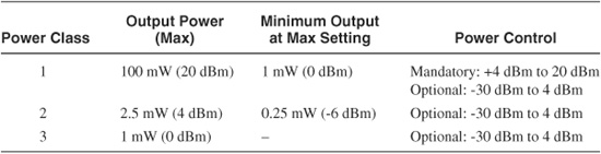
Power control operates by a receiver monitoring the Received Signal Strength Indication (RSSI) and sending LMP control commands back to the transmitter, asking for their transmit power to be reduced if the RSSI value is higher than that strictly necessary to maintain a satisfactory link. Should the RSSI value drop too low, then the receiver may request the power to be increased. The specification requires power to be controlled in steps of 2 dB to 8 dB, while RSSI measurements must be accurate to ± 4 dB at -60 dBm, with a minimum range of operation of 20 ± 6 dB, starting at -60 dB.
3.6 Radio Performance Parameters
The Bluetooth specification gives minimum performance parameters for the RF system. However, care must be taken because several of the parameters are only acceptable on paper and in particular do not address the real-world scenarios in which Bluetooth is to be employed. It is for this reason that many commercial Bluetooth RF devices significantly exceed the specified performance.
Bluetooth is specified to operate with a maximum Bit Error Rate (BER) of 0.1%. This gives a figure for receiver sensitivity of -70 dBm as described in the Bluetooth specification. In practice, receivers often exceed this by 10 or more dBm.
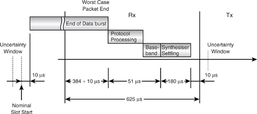
The specification does not give figures for synthesiser settling time. However, due to the high bandwidth of processing operations in the lower layers of the protocol stack, synthesiser settling time is a key performance parameter of any system. Figure 3–1 illustrates the timing of operations during any Rx / Tx transaction. The lower layer’s protocol processor must first decide what state to put the baseband link controller into and program various associated data into the baseband. The baseband is then able to calculate the appropriate frequency hop channel number and program the synthesiser. This must of course occur long enough before the expected start of the data burst to allow the synthesiser to settle. This imposes a practical limit on the synthesiser settle time of around 180 μs, and indeed many radios have settle times much lower, between 130 μs to 170 μs. The lower the settling time, the fewer are the performance requirements placed on the protocol processor.
3.7 Simple RF Architecture
There are various alternative radio system architectures such as zero IF or direct conversion, heterodyne or single bit modulation, multi-bit IQ sample modulation using lookup tables, and even direct transmit modulation onto the transmit synthesiser. However, in this section, we consider a simple single bit modulation heterodyne radio as an illustration of the various components that constitute a typical Bluetooth RF system. The block diagram in Figure 3–2 shows such a typical radio system. The control signals (TxOn, PaOn, VcOn, RxOn) are timing strobes derived from an intra slot time base by comparing against preset time values, together with a receive / transmit selection signal (Rx/nTx), which indicates whether to receive or transmit in the current slot.
Figure 3–2 Simple radio system with direct connection to the baseband.
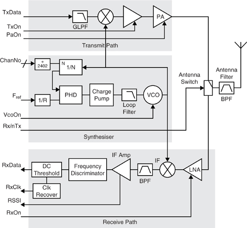
Data is clocked into the transmit path bit-serially (TxData) under control of the baseband transmit clock (TxClk) derived directly from the timebase. On receive, data is clocked into the baseband from the radio (RxData) under control of the receive clock (RxClk). RxClk may be provided either by the radio or it can be derived within the baseband. In either case, a clock recovery circuit is required. As explained previously, this does not need to be a complicated mechanism due to the relatively high tolerance on the symbol clock of ± 20 ppm. A form of digital Phase Locked Loop (PLL) is typically used.
The Bluetooth channel number (ChanNo) must be provided by the baseband to the RF channel synthesiser, which produces the exact carrier frequency to use in the IF mixer. The channel frequency required is 2402 + ChanNo MHz.
Turning on the various sections in the radio is controlled by the timebase. A number of timebase values referenced to the start of a slot are preset within the baseband and these control signals to the RF system, which power up or down various sections of the radio during receive or transmit operations. Typically, the following signals are used: VcoOn, TxOn, PaOn, and RxOn to enable the synthesiser, transmit path, power amp, and receive path, respectively.
3.7.1 Channel Number Selection
Frequency selection is communicated to the RF device by simply passing the frequency hopping generated channel number. To support reduced hop schemes in different countries, an offset may need to be added to the frequency hop channel as shown in Table 3–1.
Table 3–1 ISM Band Availability by Geographical Location
3.7.2 Receive Clock and Data Recovery
The function of clock recovery is to retrieve a valid clock signal with which to validate the received data. Due to the relatively tight symbol timing tolerance described above, which results in only one-eighth of a symbol error at the end of a maximal (5 slot) length packet, Bluetooth clock recovery does not necessarily need to be active across the entire packet. Practical experience shows that the optimum mechanism employed for clock recovery is really dependent on the radio architecture used. Two variants of clock recovery are in common use for Bluetooth systems. The first type attempts to recover the clock based on knowledge of the expected preamble sequence of four bits plus the first synchword bit, while the second is a more common technique in systems such as DECT, where a simple digital PLL-type circuit detects edges in the incoming data stream, adjusting the phase of the recovered clock to track the data edges with an overall hysteresis to manage glitches and wide symbols. This is sometimes referred to as an “early-late” synchroniser.
In both cases, the important and reliable component of the data to recover the clock from is the 5 bit preamble sequence (including the first bit of the synchword). However, most radios will lose the first one, two, or even three symbols due to slew in the analog receive path and DC thresholding circuit. The result of this is that only one or two symbols are available for clock recovery, and experience shows that really four or five are required as a minimum. Moving in to the synchword and using some of these bits is the usual answer, and indeed, the early-late synchroniser does this automatically. However, using more than one or two synchword bits starts to eat into the correlation threshold uncertainty and will reduce overall link sensitivity. DECT by comparison uses a preamble sequence of 16 bits.
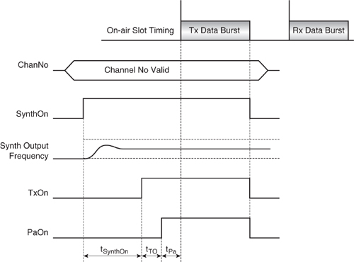
3.8 Rf System Timing
The timing diagrams in Figures 3–3 and 3–4 illustrate the relative timing of the various control signals on the radio. Specific values of these will appear in manufacturers’ data sheets.
Figure 3–3 Receive slot timing
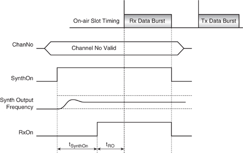
Figure 3–4 Transmit slot timing.
3.9 Blue Rf
An initiative was started by several companies in mid 1999 to standardise the interface between baseband and radio around a minimal number of signals and control so as to minimise device pin count and provide for interchangeability of parts and second-sourcing opportunities. Many radio device manufacturers have signed up to join the BlueRF consortium, but the original goal of one standard interface for Bluetooth radio chips has not been realised. Today, the BlueRF specification is no longer maintained and promoted and each manufacturer has made their own implementation of the specification. However, what has resulted is a form of de-facto standardisation, where the vast majority of interfaces fall within a set of guidelines as described by the following BlueRF summary.
Essentially, two different modes of operation are provided for: bidirectional, which provides the lowest pin count but requires control logic in the radio to sequence on-air operation, and unidirectional, which simplifies the radio and allows it to be completely controlled by the baseband but demands a higher pin count.
In addition to this, there are three receive modes which alter the partition between RF and the baseband device for Rx. These are defined as follows:
- RxMode1—The radio only contains the demodulator and the baseband contains the DC thresholding and data extraction (including the correlator) circuitry.
- RxMode2—The radio contains the demodulator and DC thesholding circuitry, and the baseband contains the data extraction circuitry.
- RxMode3—The radio contains all three functions.
In each case, the pin count is reduced at the expense of a more complex radio design.
3.10 Summary
Bluetooth devices operate at 2.4 GHz in the globally available, license-free ISM band. Although widely available, the use of this band by many other systems and the pollution of it by other sources such as microwave ovens make this a rather hostile environment. Blue-tooth employs a fast frequency hopping scheme to counteract this, together with error protection and correction.
The specification of the radio requirements has been relaxed as far as possible to facilitate low cost and low power design. The modulation used is simply GFSK with one symbol per bit, providing a gross bit rate of 1 Mb/s from a channel bandwidth of 1 MHz. By specifying tight constraints on symbol timing and drift rate, the task of recovering the received data stream is also simplified.
In spite of this, there are some key design issues to be addressed in making such a low cost system reliable and robust, and some close attention must be given to system design. Other parts of the Bluetooth specification itself impose some constraints on the radio system and these must also be accounted for.
To facilitate the reuse and interoperability of radio parts with different baseband devices, an initiative named BlueRF has been launched to standardise the Bluetooth radio interface and this has been somewhat successful.