
10
Rfcomm
RS-232 serial ports have nine circuits, which can be used for transferring data and signalling. RFCOMM can emulate the serial cable line settings and status of an RS-232 serial port. RFCOMM provides multiple concurrent connections by relying on L2CAP to handle multiplexing over single connections, and to provide connections to multiple devices.
RFCOMM relies on the Bluetooth baseband to provide reliable in-sequence delivery of byte streams. It does not have any ability to correct errors. Up to version 1.0b RFCOMM’s flow control relied entirely on the baseband’s capabilities, but in version 1.1 RFCOMM acquired a credit based flow control system which allows individual RFCOMM channels to maintain seperate flow control.
RFCOMM data rates will be limited in devices where there is a physical serial port involved (Type 2 devices). Implementations may optionally pace data on virtual serial ports (in Type 1 devices). In the absence of pacing, RFCOMM will deliver the highest possible data rate, although what the highest data rate is can be a complicated issue in the presence of multiple connections (see Chapter 18).
RFCOMM is a simple, reliable transport protocol with framing, multiplexing, and the following additional provisions:
- Modem status—RTS/ CTS, DSR/ DTR, DCD, ring.
- Remote line status—Break, overrun, parity.
- Remote port settings—Baud rate, parity, number of data bits, etc.
- Parameter negotiation (frame size).
- Optional credit based flow control.
10.1 Serial Ports And Uarts
Typically, serial port transmit and receive data lines are connected to a UART (Universal Asynchronous Receiver Transmitter). The job of the UART is to convert between the serial data sent down cables and the parallel data processing which devices use. UARTs use buffers to convert between serial and parallel data. This allows them to reduce the load on the processor. Instead of the processor having to be interrupted for every single bit that is sent down the cables, the UART transfers the bits between the cables and buffers, then the processor only has to get involved when there is a whole buffer to deal with.
The signals from a UART are connected, so they appear in the system address map. Some processors reserve a special range of addresses for I/O; other systems can map them into any part of normal memory. Because UARTs look like areas of memory to a microprocessor, it is possible to emulate a serial port in software by taking an area of memory and setting values as they would appear if they were set by a UART.
The Bluetooth RFCOMM specification talks about emulating the nine circuits of an RS-232 serial port, and specifies how a serial data stream can be emulated. But because the serial stream from an RS-232 port is viewed by the microprocessor after it has been through a UART, software dealing with serial ports is actually handling parallel data. Similarly, RFCOMM software deals with parallel data delivered by the lower layers of the Bluetooth stack.
A UART connects to some piece of hardware: wires or buffers. RFCOMM connects up to the lower layers of the software stack via L2CAP.
10.2 Types Of RFCOMM Devices
RFCOMM supports two types of devices:
- Type 1—Internal emulated serial port (or equivalent).
- Type 2—Intermediate device with physical serial port.
A protocol stack for a Type 1 RFCOMM device is shown on the left in Figure 10–1. The port emulation entity maps a system specific communication interface (API) to the RFCOMM services. This can be used to connect to legacy applications as shown, or it can be used to connect to applications specifically written for Bluetooth. A Type 1 device would usually be the end of a communication path, for example, a PC or printer.
Figure 10–1 Type 1 and Type 2 RFCOMM devices.
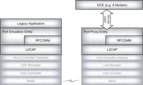
A protocol stack for a Type 2 RFCOMM device is shown on the right in Figure 10–1. The port proxy entity relays data from RFCOMM to an external RS-232 interface linked to another device. Type 2 devices are intermediate devices which sit in the middle of a communication path. A modem is an example of a Type 2 device.
10.3 RFCOMM Frame Types
RFCOMM is based on GSM TS 07.10, which is an asymmetric protocol used by GSM cellular phones to multiplex several streams of data onto one physical serial cable. RFCOMM is symmetric, and sends TS 07.10 frames over L2CAP using a subset of TS07.10 feature frames and commands. Some of TS 07.10’s features are adapted for Blue-tooth.
RFCOMM communicates with frames. The RFCOMM frames become the data payload in L2CAP packets. There are five different frame types:
- SABM—Start Asynchronous Balanced Mode (startup command).
- UA—Unnumbered Acknowledgement (response when connected).
- DISC—Disconnect (disconnect command).
- DM—Disconnected Mode (response to a command when disconnected).
- UIH—Unnumbered Information with Header check.
SABM, UA, DM, and DISC are “low- level” control frames. RFCOMM uses channels, each of which has a Data Link Connection Identifier (DLCI). UIH frames on DLCI = 0 are used to send control messages. UIH frames on DLCIs ≠ 0 are used to send data.
GSM TS 07.10 also has optional UI (Unnumbered Information) frames; RFCOMM doesn’t use these.
10.4 Connecting And Disconnecting
Because RFCOMM frames are carried in the payload of L2CAP packets, an L2CAP connection must be set up before an RFCOMM connection can be set up.
RFCOMM has a reserved Protocol and Service Multiplexer (PSM) value which is used by L2CAP to identify RFCOMM traffic. The RFCOMM PSM is defined in the Bluetooth core specification as 0x0003. Any L2CAP frames received with this value in the PSM field will be sent to RFCOMM for processing.
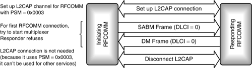
The first frame to be sent on an RFCOMM channel is a SABM frame; this is a Start Asynchronous Balanced Mode command. If the responding device’s RFCOMM is willing to connect, it goes into Asynchronous Balanced Mode (ABM) and sends back an UA frame. If the responding device’s RFCOMM doesn’t want to connect, it refuses the connection by sending a DM frame. Figure 10–2 shows an RFCOMM channel setup being refused in this way.
RFCOMM has a 60 s timer which is started when a command is sent. If an acknowledgement isn’t received when the timer elapses, the connection will be shut down. This is different from GSM 07.10, which resends the command when the timer elapses. In the case of RFCOMM, the Bluetooth baseband provides a reliable link, so if the command wasn’t acknowledged first time, it is not likely to be acknowledged a second time. For the SABM command, the timeout can be extended because security procedures might mean that this command takes longer to process than others. If RFCOMM ever times out and disconnects, it must send a DISC (disconnect) command frame on the same DLCI as the original SABM frame, just in case the other side has come back into range and thinks the connection is still active. Figure 10–3 shows a channel being closed down because the initiator timed out.
Figure 10–2 Refusing an RFCOMM connection.
If the connection succeeds, the responder replies to the SABM frame with a UA (un-numbered acknowledgement) frame. This is followed by a Parameter Negotiation (PN) command from the initiator and PN response from the responder, as shown in Figure 10–4.
Once a connection with DLCI = 0 has been set up, this is available for RFCOMM signalling. To transfer data, other RFCOMM channels must be set up. Figure 10–4 shows a second RFCOMM channel being set up to transfer data. In this case, the channel requires authentication, so there is a pause for LMP authentication and encryption between the SABM command frame and the UA response frame. Once the UA frame has been received, modem status commands are exchanged to communicate the state of the control signals. Data can then be transferred immediately as shown, or there could be an exchange of PN command and response to configure the new connection’s parameters.
The user data should include MSCs (Modem Status Commands), which communicate the state of serial port control signals.
To shut down an RFCOMM connection, a DISC command is sent. When the last data link has been shut down, a DISC should be sent on DLCI=0 to shut down the multiplexer. Then, whichever device shut down the multiplexer is responsible for disconnecting the L2CAP channel.
10.5 Structure Of Rfcomm Frames
RFCOMM borrows its frame structure from the GSM 07.10 standard. Figure 10–5 shows the frame structure for the GSM 07.10 basic option. (There is also an advanced option, which lacks the length field; RFCOMM always uses the basic option.)
Figure 10–3 RFCOMM channel timeout.
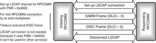
Figure 10–4 Message sequence chart for establishing an RFCOMM connection.
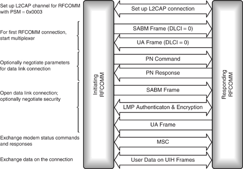
Figure 10–5 Structure of a GSM07.10 basic option frame.
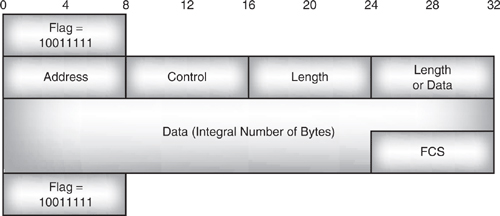
Figure 10–6 Structure of an RFCOMM frame.
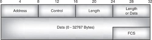
Figure 10–6 shows the structure of an RFCOMM frame. This is identical to the GSM07.10 basic option frame except that RFCOMM misses out the start and end flags, and RFCOMM has to limit the number of bytes in a packet because of the limit on the size of L2CAP packets.
RFCOMM doesn’t need the start and end flags because each RFCOMM frame is carried in a single L2CAP packet. There is no need to pick RFCOMM frames out of a data stream, so there is no need for flag bits to mark where the frames start and end.
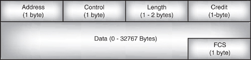
Figure 10–7 shows how the RFCOMM frame structure changes when credit based flow control is in use. The length field is followed by a credit field which is used to give the remote device permission to send frames.
10.5.1 Address Field
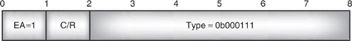
An RFCOMM frame begins with an address field. This identifies which of the many multiplexed channels the frame belongs to. The address field is split up as shown in Figure 10–8.
The EA (Extend Address) field can be used to extend an address. If EA=0, then more address octets follow; if EA=1, then this is the last octet of the address. Since the Bluetooth specification says that server applications are assigned a server channel number in the range 1 to 30 and an RFCOMM address frame has five bits for the server channel, there will never be any need to use extended addressing, so the EA bit will always be set to 1 in an RFCOMM address field.
Figure 10–7 Structure of an RFCOMM frame with credit based flow control.
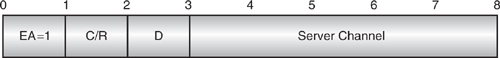
The C/R (Command/Response) bit says whether the frame is a command or a response. Its value depends not only on whether the frame carries a command or a response, but also on which end of the channel is sending the frame. The device which set up the connection (by sending a SABM command on DLCI 0) is called the initiator. The device which responded (by sending the UA response on DLCI 0) is called the responder. As long as the traffic follows this original pattern, the C/R bit is 1, so commands from the initiator and responses from the responder have C/R = 1. For exchanges in the opposite direction, the C/R bit is 0, so commands from the responder and responses from the initiator have C/R = 0. When sending data, the initiator sets C/R = 1 and the responder sets C/R = 0. Figure 10–9 illustrates how the C/R bit is set.
After the C/R bit comes the Data Link Connection Identifier (DLCI). In GSM TS0.10, this is one undivided field, but in RFCOMM, it is split up into a direction bit and a server channel number. The initiator always sets the direction bit to 1 (D=1); the responder always sets the direction bit to 0 (D=0). As with the C/R bits, who is the initiator and responder is defined by which device sent the SABM frame to start up the connection.
Figure 10–9 Settings of C/R bit in RFCOMM exchanges.
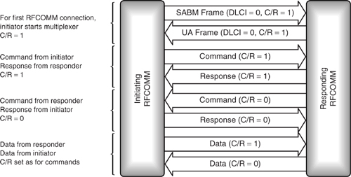
Table 10–1 Control Field Values
The server channel number has five bits; this would give it a range from 0 to 31, but 0 and 31 are reserved, so only 1 to 30 can be allocated as server channel numbers for services. Channel 0 is used for sending control information; channel 31 is reserved by TS07.10. Bluetooth avoids using channels which are reserved by TS 07.10 to preserve compatibility with TS 07.10 applications.
The DLCI is calculated once before the data link connection is established. The RFCOMM server channel number in the responding device is used for the DLCI. Because server channel numbers 1 to 30 are available, one device can have up to 30 services using RFCOMM.
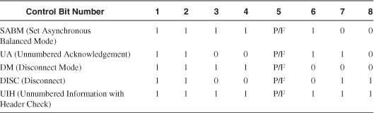
10.5.2 Control Field
Referring back to Figure 10–6, the next field in an RFCOMM frame is the control field. This is used to identify the type of the frame. Table 10–1 shows the control field values used in RFCOMM frames. (These match the values used in the corresponding GSM TS 07.10 Frames.)
P/F is the Poll/Final bit. In commands, it is called the P (Poll) bit; in responses, it is called the F (Final) bit.
A command with its P bit set to 1 is used when a response or a series of responses is wanted from the device at the far end of the link. The responding device should send back its responses with the F bit set to 1. There should only ever be one command frame with P bit set to 1 waiting for a response.
DM packets are processed regardless of the state of the P/F bit, but SABM or DISC commands and UA responses are thrown away if the P/F bit is set to zero.
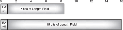
10.5.3 Length Field
The length field begins with an EA bit as shown in Figure 10–10. If this is 1, then it is followed by seven bits of length, so the length field is one byte long. If the EA bit is 0, then it is followed by fifteen bits of length, so the length field is two bytes long.
The default length of an RFCOMM frame is 32 bytes; the maximum length is 32,767.
Figure 10–10 Structure of RFCOMM length fields.
10.5.4 Credit Field
The credit field only exists when the use of credit based flow control has been negotiated. An initial number of credits is granted using three bits in the parameter negotiation command. Each unit then keeps track of how many credits it has. Each time an RFCOMM frame is sent one credit is used up, each time a frame with a non-zero credit field is received, the value in the credit field is added onto the receiving units total credits.
10.5.5 Data
The data field is only present in UIH frames. There must be an integral number of bytes in the data up to 32,767. The size limit is set by the Maximum Transmission Unit (MTU) on L2CAP packets, so if a system has a smaller L2CAP MTU, the size of RFCOMM data will also be restricted.
10.5.6 Frame Check Sequence
To calculate the FCS:
Count up k, the number of bits the FCS will be calculated on. For SABM, DISC, UA, and DM frames, the frame check sequence is calculated on the address control and length fields. For UIH frames, it is calculated on the address and control fields.
Then:
(a) Calculate the remainder of xk (x7 + x6 x5 + x4 + x3 + x2 + x1 + 1) divided modulo 2 by the generator polynomial (x8 + x2 + x + 1).
(b) Take the contents of the frame that the FCS is calculated over before any start and stop elements have been inserted and before any other extra bits have been inserted. Multiply by x8 and divide by the generator polynomial (x8 + x2 + x + 1).
(c) Add the results of (a) and (b) modulo 2, and take the 1’s complement to get the FCS.
Because UIH frames only calculate FCS on the address and control fields, their data field is not protected by the FCS. This might be a drawback for reliable data transmission, but it does have the advantage that the FCS patterns can be precalculated for all the DLCIs that are in use. This precalculation could be done when the channel is set up.
10.6 Multiplexer Frames
Multiplexer commands and responses are sent on DLCI = 0. They are used to control the RFCOMM link. There are seven types of commands or responses:
- PN—DLC parameter negotiation.
- Test—Checks communication link.
- FCon / FCoff—Aggregate flow control on all connections.
- MSC—Modem status, used for flow control per connection.
- RPN—Remote Port Negotiation.
- RLS—Remote Line Status.
- NSC—Non-Supported Command (response only).
The multiplexer commands and responses are carried as messages inside an RFCOMM UIH frame as shown in Figure 10–11. It is possible to send several multiplexer command messages in one RFCOMM frame or split a multiplexer command message over more than one frame.
10.6.1 PN—DLC Parameter Negotiation
The PN command is used to negotiate the parameters of a data link connection. PN commands are exchanged before a new data link connection is opened. In version1.0b this was not compulsory; in version 1.1 parameter negotiation became mandatory.
In pre-version 1.1 systems, if no PN commands are sent, default parameters will be used for the connection. This means that pre-version 1.1 systems must be able to support the default RFCOMM frame length.
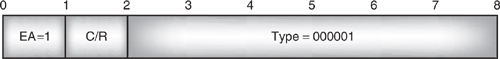
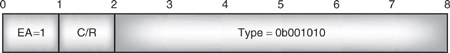
A PN command is identified by the type field shown in Figure 10–12. This type field is the first information byte in the UIH frame carrying the PN command (see Figure 10–12). The EA bit is 1 because the type field occupies one byte. The C/R bit is used to indicate whether the message is a command or a response.
Figure 10–11 Structure of an RFCOMM multiplexer control frame.
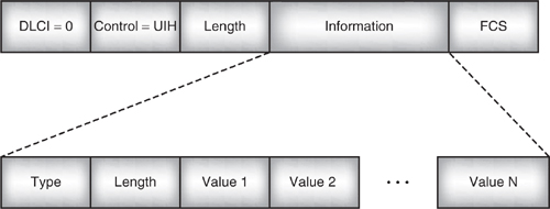
Figure 10–12 Type field for Parameter Negotiation (PN).
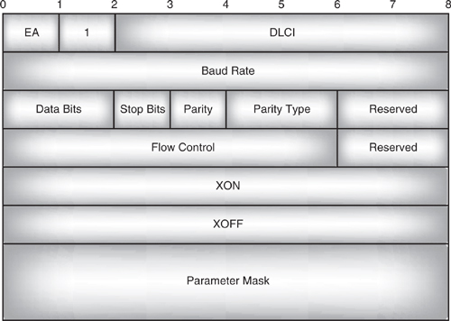
The length field in a PN message is always set to 8, and the value field contains 8 bytes as shown in Figure 10–13. These bytes define the parameters which will be used on a data link connection as follows:
Figure 10–13 Content of value bytes in a PN message.
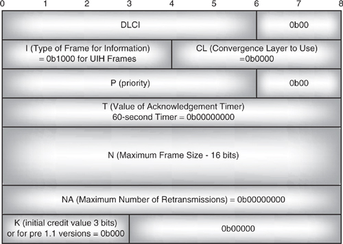
- Six DLCI bits identify the data link connection for which parameters are being negotiated.
- Two padding bits which are always set to zero follow the DLCI; these are inserted to avoid splitting parameters across bytes.
- Four I bits give the type of frames used to carry information on the channel. In RFCOMM UIH frames indicated by the value 0b1000 are used.
- Four CL bits give the convergence layer to be used. RFCOMM uses Type 1 (unstructured octet stream) = 0b0000 in versions after 1.0b this may also be set to 0x0F to enable credit based flow control.
- Six P bits assign a priority to the data link connection: 0 is the lowest priority, 63 is the highest.
- Two padding bits which are always set to zero follow the P bits; these are inserted to avoid splitting parameters across bytes.
- Eight T bits give the value of the acknowledgement timer, in GSM 07.10, this would be used to trigger a retransmit; in RFCOMM, if the timer elapses, the connection is closed down. The timer’s value is not negotiable, but is fixed at 60 μs. This field is set to 0 to indicate that the timer is not negotiable.
- Sixteen N bits give the maximum size of the frame.
- Eight NA bits give the maximum number of retransmissions. Because the Bluetooth baseband gives RFCOMM a reliable transport layer, RFCOMM will not retransmit, so this value is set to zero.
- Three K bits are used to indicate the initial number of credits issued to a peer; the initial credit value can range from 0 to 7. If credit based flow control is not used, the k1-k3 bits are set to zero.
- Five padding bits set to zero fill the rest of the last value field to round up the values to an integral number of bytes.
All parameters being negotiated are sent with the LSB in bit 1; this is the general rule for RFCOMM information.
It is worth noting that RFCOMM follows the conventions of the GSM 07.10 standard and numbers the bits in a frame from 1 for the least significant bit to 8 for the most significant bit. This may be confusing to people who are used to seeing the bits in a byte numbered from 0 to 7.
One device sends a PN message, and the other responds with another PN message. The response may not change the DLCI, the priority, the convergence layer, or the timer value. The response may send back a different timer value. In this case, the device which sent the first PN messages will still use the timer it proposed, but the device at the other end of the connection will use the value it sent in its message.
The response may have a smaller value for the maximum frame size, but it may not propose a larger value for this parameter.
In GSM 07.10, PN messages are optional. In RFCOMM, support of the PN message and its response are compulsory. Up to version 1.0b if default parameters are satisfactory, PN messages do not have to be sent. Version 1.1 made PN messages mandatory, even if the default parameters are satisfactory. PN messages may be exchanged until the device which sent the first message is happy with the parameters it gets sent back to it. Once it has a satisfactory set of parameters in the reply, it can go on to set up the connection.
One reason for parameter negotiaton mandatory was to enable negotiation of credit based flow control. Without mandatory parameter negotiation the responding unit could be left with no opportunity to negotiate. When not using credit based flow control, RFCOMM channels used FCON and FCOFF messages for flow control on individual channels. Because Bluetooth channels are unreliable, these messages could require several retransmissions to switch off the flow of packets. This could lead to RFCOMM layer buffers overflowing and data being lost. Therefore, applications which would suffer if data buffers overflow must negotiate credit based flow control.
Figure 10–14 Type field for test.
10.6.2 Test
The test command is used to check the RFCOMM connection. As is normal, the length byte gives the number of value bytes which follow. The number of value bytes is not fixed and is used to hold a test pattern. The remote end of the link echoes the same value bytes back.
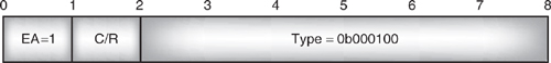
The type field for the test command is shown in Figure 10–14. Because only a single byte is used, the EA bit is set to 1. The C/R bit is used to indicate whether the message is a command or a response.
10.6.3 FCon / FCoff—Aggregate Flow Control on All Connections
RFCOMM has a flow control mechanism which applies to all channels between two RFCOMM entities. When either RFCOMM entity can’t receive RFCOMM information, it sends a Flow Control off (FCoff) command. When it is able to receive data again, it sends a Flow Control on (FCon) command.
The structure of the type field for the two flow control commands is shown in Figure 10–15. Both begin with an EA bit, which is 1 to indicate that there is only one byte in the command type. The length field in the frame carrying the command is set to zero because there is no other data in the frame. The C/R bit is used to indicate whether the message is a command or a response.
Figure 10–15 Type fields for FCon and FCoff commands.
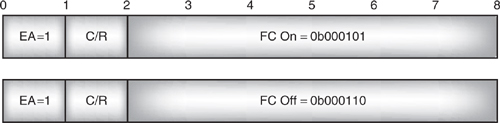
Figure 10–16 Type field for MSC command.
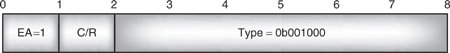
10.6.4 MSC—Modem Status Command
RFCOMM also has a flow control mechanism which can be applied to just one channel at a time. This is the Modem Status Command (MSC), and it is indicated by the type field shown in Figure 10–16. The EA bit is 1 because the type field occupies one byte. The C/R bit is used to indicate whether the message is a command or a response.
The command field of the MSC contains virtual V.24 control signals—that is to say, the settings that the RS 232 control wires would have if the RFCOMM data were being transferred across wires rather than across a Bluetooth connection. The signals in the command field are as follows:
- EA—Extended Address, set to 1 to indicate there is only 1 byte of command.
- FC—Flow Control bit, set to 1 when a device is unable to accept any RFCOMM frames. When the device is able to receive again, it sends another MSC with the flow control bit set to 0.
- RTC—Ready To Communicate bit, set to 1 when the device is ready to communicate.
- RTR—Ready To Receive bit, set to 0 when the device cannot receive data and 1 when it can receive data.
- IC—Incoming Call, 1 indicates an incoming call.
- DV—Data Valid, set to 1 to indicate that valid data is being sent.
These values may not seem to make sense when sent in a packet, but that is because they map onto the lines of an RS 232 interface. It might be obvious when a packet is sent that it is going to have valid data; who would bother to send a packet with invalid data? However, when dealing with physical serial port lines, such signals make more sense. A signal to say that valid data is being sent can be used to activate circuits to handle the data. The MSC command just mimics the values of the V.24 signals, which would be used on a wired RS 232 interface.
The signals from an MSC map onto RS 232 signals as follows:
- RTC maps onto DSR (Data Set Ready) and DTR (Data Terminal Ready).
- RTR maps onto RTS (Request To Send) and CTS (Clear To Send).
- IC maps onto RI (Ring Indication).
- DV maps onto DCD (Data Carrier Detect).
Figure 10–17 MSC control signal field.
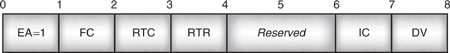
Figure 10–17 shows how the signals are carried in the control field of the command. The MSC is sent on a connection before any data is sent to establish the state of the RS 232 control signals. It should also be sent whenever the signals need to be changed.
In the MSC, the state of the signals in the device sending the command is sent. The response just carries a copy of the signals from the command.
10.6.5 RPN—Remote Port Negotiation
The Remote Port Negotiation (RPN) command is used to set communication settings at the remote end of a data link connection. If any of the communication settings need to be changed during a connection, the RPN command can be resent to change them.
The RPN type field is shown in Figure 10–18.
The EA bit is 1 because the type field occupies one byte. The C/R bit is used to indicate whether the message is a command or a response.
The length byte in an RPN command is either 1 or 8. If the length is 1, then there is a single value byte which contains the DLCI for the connection, and the message is interpreted as a request for the link’s parameters. In this case, the remote end replies with the current parameters on the link. If the length byte is set to 8, then eight bytes of link parameters follow. If they are sent in a command, then they are a request to set up the link’s parameters.
Figure 10–19 shows the order of values within an RPN command with length byte set to 8.
The parameter mask defines which parameters are being changed by the message. Figure 10–20 shows the position of bits in the RPN parameter mask.
In an RPN command, if a parameter mask bit is set to 1, it indicates a particular parameter that should be changed. If it is set to 0, then the parameter is not being changed and the value can be ignored.
In an RPN response, if a parameter mask bit is set to 0, then it means the proposal sent in an RLS has not been accepted. Conversely, a parameter mask bit set to 1 means the new value has been accepted, and the sender of the response is now using the new value.
Figure 10–18 Type field for RPN.
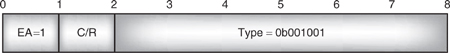
Figure 10–19 Value bytes in a RPN command.
The values of the various fields in an RLS command have the same meanings as in GSM 07.10.
10.6.6 RLS—Remote Line Status
A device sends a Remote Line Status (RLS) command when it needs to tell the other end of the link about an error.
Figure 10–20 Bits in an RPN parameter mask.
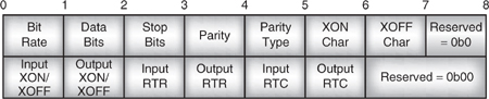
Figure 10–21 Type field for RLS.
The RLS command is identified by the type field shown in Figure 10–21. The EA bit is 1 because the type field occupies one byte. The C/R bit is used to indicate whether the message is a command or a response.
The length byte is set to 2, as there are two value bytes: the first value byte carries an EA bit, C/R bit, and the data link connection identifier common to all multiplexer command messages; the second value byte carries the error status in its first four bytes as shown in Figure 10–22.
The Line (L) status bits can signal three different errors as follows:
- 0b1100—Overrun error, a received character has overwritten a character which had not yet been read.
- 0b1010—Parity error, the parity was wrong on a received character.
- 0b1001—Framing error, a character did not end with a stop bit.
If the first line status bit is set to 0, then the RLS command is simply reporting that there are no errors on the line.
When an RLS command is received, a response is sent back with the line status copied from the command into the response.
RFCOMM implementations must recognise and respond to RLS commands, but how they deal with the line status information is up to the implementor to decide.
10.6.7 NSC—Non-Supported Command (Response Only)
The Non-Supported Command (NSC) Response is sent whenever a device receives a command it does not support.
The type field used to identify a message containing an NSC is shown in Figure 10–23. The EA bit is 1 because the type field occupies one byte. The C/R bit is used to indicate the message is a response. If the message comes from the device which initiated the connection by sending a SABM, then C/R = 0. If the message comes from the device which responded to the initial SABM, then C/R = 1.
Figure 10–22 Second value byte of RLS message.

Figure 10–23 Type field for NSC response.
10.7 Service Records
Bluetooth devices offering services supported by RFCOMM must have an entry in their service discovery database which gives information on how to connect over RFCOMM.
RFCOMM server channel numbers are dynamic. That is to say, a service’s channel number can change. Although a service’s channel number doesn’t change while the service is in use, it can be reallocated when the service is not in use.
The minimum information needed to connect to a service over RFCOMM is a service name (to identify the type of service) and a channel number on which to transfer data. Many services will have other additional parameters which are also needed to connect to the service. By querying SDP records, a device can find out all the information it needs to connect to a service via RFCOMM.
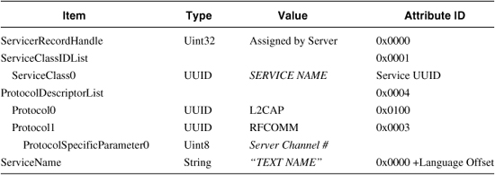
Table 10–2 shows a minimal service record which might be used to provide the information needed to connect to a service across RFCOMM. The ServiceClassIDList gives the name of the service. The ProtocolDescriptorList gives the supported protocols. Since RFCOMM rests on L2CAP, the L2CAP service must be present whenever RFCOMM is present. This service also has a text name which can be used to represent it on a user interface.
For more information, see Chapter 11, Table 11–1, which shows how RFCOMM information is presented for a headset application. The headset application also uses RFCOMM services to set up and control headset connections.
Table 10–2 Service Attributes Needed to Connect to an RFCOMM Service
10.8 Summary
RFCOMM provides serial port emulation, which can be used to connect to legacy applications. It is also used for data transfer in several of the Bluetooth profiles.
RFCOMM supports two types of devices: A Type 1 device is the end of a communications path and supports an application on top of RFCOMM, and a Type 2 device is an intermediate device and has a physical RS-232 serial port on top of RFCOMM.
To set up an RFCOMM connection, an L2CAP connection must first be set up. RFCOMM frames are sent in the payload field of L2CAP packets. Once the L2CAP connection is set up, RFCOMM control frames are sent back and forth to establish a signalling channel with a Data Link Connection Identifier (DLCI) set to 0. After this is set up, subsequent channels are established for transferring data. Up to 30 data channels can be set up, so RFCOMM can theoretically support 30 different services at once. (In practice, most Bluetooth devices will not have the resources to support 30 different services.)
RFCOMM is based on the GSM 07.10 standard with a few minor differences to allow for the differences between a Bluetooth connection and a GSM cellular phone connection.