
Designing an Audio Application
Introduction
Bluetooth technology began in the labs of Ericsson, a major player in the mobile phone market, so it’s not surprising that voice quality audio links play a large part in the capabilities of Bluetooth technology. According to Semiconductor Business News’ market research report in its May 2001 edition, Cirrus Logic, which has a large share of the market for digital audio players and other portable consumer electronics, says it will begin building Bluetooth into its popular Maverick embedded processor. The Maverick processor features Internet appliances and Internet audio players.
Moreover, the Bluetooth specification will support the next generation of cellular radio systems for mobile telephony known as third generation (3G) that has been defined by the International Mobile Telecommunications 2000 (IMT-2000) program. The first group of audio/telephony profiles available for public with the current Bluetooth Specification v1.1 includes headset, intercom, and cordless phone.
Today, there are voice-command mobile phones and even voice-enabled Internet browsing, so audio applications and their capabilities can be a little too rich at times. Before writing an audio application, we need to understand the expectations of our target users. Do they want to transmit and receive near-CD quality audio? Do they want an acceptable range for home use with no extraneous sounds, clicks, or silences intruding? Do they want to listen to music, or hold a three-way phone conversation? We also need to know whether we are writing generic code to fit into bulky static devices such as stereos, or if we are producing a compact purpose-built system such as might slot into the strictly constrained resources of a tiny portable MP3 player. There are so many possible audio applications that we can’t cover them all in detail, but this chapter will explain the basics and help you make intelligent decisions when designing your audio application.
First, we’ll look at the choice of analog-digital-analog conversion schemes (Codecs). This section explains why Bluetooth technology supports several Codecs and explains how the different types perform in the presence of errors. We then go on to look at how Bluetooth links can support multiple voice channels along with simultaneous data capabilities. We explain the Synchronous Connection-Oriented (SCO) link and the three types of voice packet (Highrate Voice [HV]1, HV2, and HV3) it uses. This section explains how each packet type is transmitted at different rates and provides different amounts of error correction.
We examine the three audio profiles released with the first Bluetooth profile specification document, and briefly touch upon profiles that are soon to be released. Then we look in detail at how you might implement one particular profile: the Headset profile.
Finally, we present a few techniques you might use to differentiate your audio application and add value for the end user.
Choosing a Codec
This section explains the different ways that Bluetooth systems encode voice for transmission on air. The product you are writing applications for may not allow you to choose a Codec, in which case you can safely skip this section. If you do need to choose a Codec type then it is worth taking time to understand what Codecs do, and why a choice of Codecs with different performance levels were incorporated in the Bluetooth specification.
There are several stages involved in getting from speech to the digital signals transmitted on a SCO link. The sounds we hear in human speech, music, and so on, are made up of pressure waves. A microphone converts those pressure waves into analog electrical signals. The analog signal from the microphone is fed into a Codec, which converts the analog signals of a voice signal into a digital signal to be transmitted over a communications medium. The digital signal is passed to the baseband for incorporating into a SCO packet; this packet is then sent to the radio for modulating onto a carrier for transmitting on air.
In the receive direction, the radio receives and demodulates the incoming digital signal, and passes it to the baseband. The baseband extracts the audio data and passes it to the Codecs. The Codecs take the digital signal and convert it to an analog signal for the speaker front end. Finally, the speakers, as we all know, take analog electrical signals and convert them into sound waves for us to hear.
In brief, microphone and speaker convert from sound waves to analog electrical signals. The Codec converts those analog signals into a digital format. The term Codec is an acronym that stands for “coder/decoder.”
It is possible to directly modulate analog signals onto a radio without first converting them into digital format. This raises the question of why anybody would bother converting analog audio into digital formats to begin with.
There are several reasons, two of which include: digital signals tend to be more robust in the noisy environments; encoding into a digital format allows error detection and correction to be added to the signal. This means that digitally-encoded speech performs much better on noisy channels.
Of course, in the case of Bluetooth wireless technology, the baseband is designed to handle digital signals, so transmitting analog audio signals is just not an option, even if it was desirable.
If all that was required was converting between analog and digital, we could just use an Analog to Digital Converter (ADC) and Digital to Analog Converter (DAC). However, the Bluetooth specification enforces a low data rate for its voice channels: the SCO links carry just 64 Kbps. At this sort of low data rate, the Codecs are required to compress the audio signal as well as convert between analog and digital formats. The Bluetooth specification supports three different audio coding schemes on the air interface:
![]() Continuous Variable Slope Delta Modulation (CVSD)
Continuous Variable Slope Delta Modulation (CVSD)
![]() Log Pulse Code Modulation (PCM) coding using A-law compression
Log Pulse Code Modulation (PCM) coding using A-law compression
CVSD is a differential waveform quantization technique that employs a two-level adaptive quantizer (one bit). PCM uses a non-uniform quantization (a large number of progressively smaller quantization levels for low amplitude signals and fewer, coarser quantization levels for larger amplitude signals).
CVSD is more robust in the presence of bit errors than PCM. With an increase in the number of bit errors in a transmission, the perceptible voice quality of PCM drops rapidly—much more rapidly than the voice quality of CVSD. On the other hand, PCM is simple, cheap, and more importantly, it is already used in a lot of devices. For error tolerance, we need CVSD, but for maximum compatibility with legacy systems, we need PCM. We’ll look at both technologies in more detail later in this section.
The overall architecture of a Codec is illustrated in Figure 9.1. On the left, the front-end amplifiers adjust the levels between those required by the microphone and speaker and those required by the converters. ADC and DAC convert the audio signal from analog to digital format. Then some type of digital signal processing (DSP) performs the Codec function. This could be a generic DSP capable of performing many functions, or the Codecs could be implemented in dedicated circuitry.

The output of the Codecs must be fed into the Bluetooth baseband. In Figure 9.1 this is shown as a direct input to the baseband (a technique commonly used in Bluetooth chips), but it is possible that the signal from the Codecs could be encapsulated in a Host Controller Interface (HCI) packet and fed across the Host Controller Interface. (This might be done, for instance, if a mobile phone with PCM Codecs were connected to a Bluetooth chip by the HCI.)
In the following sections, we shall look at the different Bluetooth Codecs in more detail.
Pulse Code Modulation
Pulse Code Modulation systems are commonly used in public and private telephone networks. In PCM systems, a waveform Codec takes samples of an analog-speech waveform and encodes them as modulated pulses, represented by logic 1 (high) and logic 0 (low). The sampling rate, or number of samples per second, is several times the maximum frequency of the analog waveform (human-voice) in cycles per second, usually at a rate of 8000 samples per second.
Why Bluetooth Technology Uses Waveform Codecs
In addition to waveform Codecs, there are source Codecs that compress speech by sending only simplified parametric information about the voice transmission (as opposed to a compressed version of the voice transmission); these Codecs require less bandwidth. Examples of source Codecs include linear predicative coding (LPC), code-excited linear prediction (CELP), and multipulse, multilevel quantization (MP-MLQ).
So, if source Codecs require less bandwidth, why does the Bluetooth specification use waveform Codecs? There are two main reasons. First, the PCM Codecs specified in the Bluetooth specification follow existing standards. The International Telecommunication Union (ITU-T) coding techniques and Recommendation G.711 specify the waveform Codec providing tables to and from linear PCM and log PCM for both A-law and μ-law compression. Because these Codecs are used by existing standards, there is a large installed base of equipment (such as mobile phones) already using them. Second, these waveform Codecs provide better quality and imperceptible impairment according to Mean Opinion Score (MOS) testing.
Using PCM A-law or μ-law is optional. μ-law compression is used in North America and Japan, and A-law compression is used in Europe, the rest of the world, and international routes. The compression schemes are as described in the following (assuming x(t) is the current quantized message, xp is the peak value of the message and y(t) is the compressed signal output):
![]()

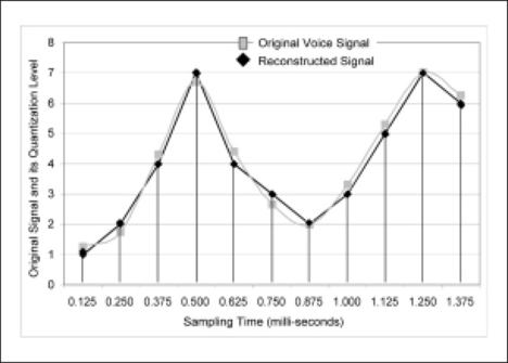
A general example of PCM coding is described in Figure 9.2. The input signal is quantized at 8KHz (meaning we take a sample every 0.125 milliseconds). For 255 code levels, we get 8 bits per sample. Therefore, we transmit 64 Kbps.
Continuous Variable Slope Delta Modulation
Continuous Variable Slope Delta Modulation was first proposed by Greefkes and Riemes in 1970. CVSD requires a 1-bit sample length compared to the 8 bits used in PCM, so more samples can be sent in the same bandwidth. As a result, CVSD is more tolerant of communications errors. Because of its error tolerance, CVSD performs well in noisy channels, and for this reason, it has been widely used in military communications systems. The ability to tolerate errors is also what makes CVSD attractive for use in Bluetooth systems.
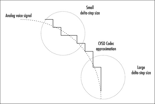
CVSD quantizes the difference in amplitude between two audio samples (that is, between the current input sample and the previous sample). The challenge is always to choose the appropriate step size δ(k). Small step sizes are better for tracking slowly changing low amplitude signals, but a larger step size is needed to accurately track a fast-changing high amplitude signal. This effect is shown in Figure 9.3.
Let’s consider a random input voice signal that we would like to convert from analog samples to digital format using CVSD. Figure 9.4 shows how this happens. As the input signal increases, bits set to 1 are transmitted. If the input signal decreases, bits set to zero are transmitted. In the first declining cosine slope of the signal, we can see how poorly the signal was quantized, but since it is an adaptive differential quantizer, it starts to adapt by changing the step size. Given this, if the signal characteristics remain the same, it will excel in following almost exactly the trace of the input signal.
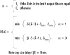
In the CVSD algorithm, the adaptive changes in step size, δ(t), are based on the past three or four sample outputs (for example, b(k), b(k-1), b(k-2), b(k-3)) where it increases or decreases to catch up with the input signal as was shown in the example of Figure 9.4 earlier. The step size, δ(t), is controlled by the syllabic companding parameter, α, which determines when to increase δ(t) or allow it to decay. The step size decay time, β, is related to speech syllable length (sometimes called delay). The Bluetooth system specifies β to be 16 ms and the accumulator decay factor, h, to be 0.5 ms.
The accumulator decay factor decides the threshold of how quickly the output of the CVSD decoders decay to zero after an input; this determines how quickly the Codec will recover from errors in the received signal. Figure 9.5 shows flow diagrams of the algorithms for the encoder and decoder. The internal state of the accumulator depends upon the equations that follow.

A standard called Mean Opinion Scale (MOS) testing is used to assess the subjective quality of voice links. A rating of 4 to 4.5 is considered toll quality (equivalent to commercial telephony). As MOS decreases, so quality decreases; a value of just less than 4 indicates communication quality with some barely perceptible distortion. Figure 9.6 compares MOS ratings for μ-law PCM and CVSD with various bit error rates on the channel.
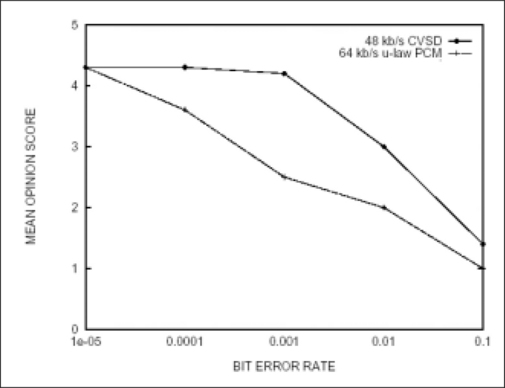
The term toll quality was first used about 22 years ago when T1 multiplexers first started transporting voice over private T1 lines. The original idea was that a private wide area network (WAN) could provide voice quality equal to that of the long-distance public switched telephone network (PSTN), which charged a toll for each minute of use using what is nowadays known as Voice Over IP (VoIP).
Notice CVSD performs as well as μ-law PCM in a clean communication medium. However, CVSD operates much better than μ-law PCM in the presence of bit errors. To be more specific, CVSD retains quite good MOS ratings at low bit error rates; however, it drops to a MOS rating of 3 (fair quality but tends to be annoying) at higher bit error rates. This robustness to bit errors (channel noise) makes CVSD an ideal solution for many wireless speech communication applications, including Bluetooth technology. But because PCM is cheap and already available in a lot of devices, we really need both.
In this section, we have described CVSD and PCM Codecs, the circumstances that governed their design, and how robust their performance is in the presence of bit errors. You may be unable to choose Codecs because you are limited by what is available in your hardware systems. Your choice may be constrained by Bluetooth profiles as well, but you should now appreciate the performance impact of choosing a particular Codec. Now that we understand Codecs, we shall turn to the code you need to write and create your audio link.
Configuring Voice Links
The Bluetooth specification provides the means for devices to transfer data and voice simultaneously using Asynchronous ConnectionLess (ACL) channels for data and SCO channels for voice. The specification also allows up to three duplex voice (SCO) channels to be active simultaneously.
The specification provides these various capabilities by using a variety of packet types (High-rate Voice HV1, HV2, HV3, or Data-Voice [DV]). The application initiating the connection configures the voice link by choosing an HV packet type. The different packet types configure the link to occupy a different percentage of the channel bandwidth. This means that the choice of packet type determines whether space is left for other voice channels, and whether it is possible to transfer data while the voice channel is active.
As always, nothing is free—adding voice channels will severely impact your ability to transfer data. Furthermore, if you choose to use multiple voice channels, each channel will have less error protection, so performance will be worse on noisy channels. If you choose to send data at the same time as voice, you will also lose out on error protection on the voice links.
Because your application’s configuration of the voice link will affect data rates and voice quality, it is important that you understand the implications of choosing different types. This section will take you through the capabilities of the different packet types, and explain their impacts on data rates and voice link quality in the presence of errors.
Choosing an HV Packet Type
Bluetooth technology uses a combination of circuit and packet switching technology to handle voice and data traffic. A circuit switched channel is a channel that provides regularly reserved bandwidth. Live audio needs circuit switched channels to guarantee regular delivery of voice information—the receive Codecs need a regular feed of information to provide a good quality output signal. The circuit switched channels are the Synchronous Connection-Oriented links—they occupy fixed slots assigned by the master when the link is first set up.
A packet switched channel is only active when data needs to be transmitted, and does not have reserved bandwidth. The packet switched channels in the Bluetooth system are the Asynchronous ConnectionLess links. If voice was sent on the ACL links, there would be no guarantee of regular bandwidth, and the quality of the received signal would suffer.
The various packets used on SCO links all provide the same symmetrical 64 Kbps between master and slave. Each packet type is sent in periodically reserved slots, but the different types require different spacings of reserved slots. Each SCO packet type, meanwhile, uses a different encoding for the payload data. The SCO packets (HV1, HV2, and HV3) are defined as follows:
![]() HV1 Carries 1.25 milliseconds (ms) of voice in 10 bytes. 1/3 Forward Error Correction (FEC) adds 2 bits of error correction for every bit of data, increasing the payload size to 30 bytes. HV1 packets are sent and received as single-slot packets in every pair of slots.
HV1 Carries 1.25 milliseconds (ms) of voice in 10 bytes. 1/3 Forward Error Correction (FEC) adds 2 bits of error correction for every bit of data, increasing the payload size to 30 bytes. HV1 packets are sent and received as single-slot packets in every pair of slots.
![]() HV2 Carries 2.5 ms of voice in 20 bytes. 2/3 FEC adds one bit of error correction for every 2 bits of data, increasing the payload size to 30 bytes. HV2 packets are sent and received as single-slot packets in two consecutive slots out of every four slots.
HV2 Carries 2.5 ms of voice in 20 bytes. 2/3 FEC adds one bit of error correction for every 2 bits of data, increasing the payload size to 30 bytes. HV2 packets are sent and received as single-slot packets in two consecutive slots out of every four slots.
![]() HV3 Carries 3.75 ms of voice in 30 bytes. There is no error correction payload. HV3 packets are sent as single-slot packets in two consecutive slots in every six slots.
HV3 Carries 3.75 ms of voice in 30 bytes. There is no error correction payload. HV3 packets are sent as single-slot packets in two consecutive slots in every six slots.
All of the SCO packets are single slot packets, and none of them carries a CRC, but we can easily see whether or not the packet types permit the flexibility to use FEC in the payload. In a noisy environment, there is no retransmission of SCO packets even if they contain errors, but the FEC scheme on the data payload protects the 80 percent of voice samples providing higher quality audio. However, the FEC encoding uses up space in the payload, so the packets that carry more error protection must be transmitted more often. In a reasonably error-free environment, FEC gives unnecessary overhead that reduces the throughput.
One more packet type can be used to carry audio data: the data-voice packet. This combines both ACL and SCO. The DV packet uses 2/3 FEC and a 16-bit CRC on the ACL data, but is without FEC on the SCO data. The DV packet carries 10 bytes of audio data, so it can be used to replace an HV1 packet—that is, it can be used on a SCO link where packets are sent every two slots.
Sending Data and Voice Simultaneously
One important question is how much voice links affect throughput of data. If we ignore the effect of errors and retransmissions, then it’s quite a simple calculation (reference Table 9.1 for maximum throughput).

With no voice links present, it is possible to use the highest rate packets: DH5 packets. These use up to five 625 μs slots each and carry at most 339 bytes of the user’s data. So, in 10 × 625μs we get a maximum of 339 bytes in each direction. This gives us 5424 bytes per second in each direction.
If we add an HV3 SCO link (the lowest load that a voice link can place on the system), then we will only have four slots in every six to transmit data. This means we cannot send five slot packets, and cannot send two consecutive three-slot packets. The most intelligent use of the available slots would be to send one three-slot DH3 packet (carrying, at most, 183 bytes of the user’s data) and one single slot DH1 packet (carrying, at most, 27 bytes of the user’s information). If the direction that sent the DH3 packet could be alternated, the bandwidth would be maximized, but both ends of the link would get the same share of the available bandwidth. Now in every 6 × 625μs, we get 183 bytes in one direction and 27 bytes in the other. Assuming the three-slot packets can be allocated so that the bandwidth averages out in each direction, our maximum data rate will average to 105 bytes transferred in each direction every 6 × 625μs. This gives us 2800 bytes per second in each direction, at 51 percent—this is almost half the maximum data rate without a SCO link present.
If we add an HV3 SCO link and just use single slot packets for data (which many basebands will do when an HV3 SCO link is active), then we get a lower throughput. In this case, we can send two DH1 packets (carrying at most 27 bytes of the user’s information), giving 54 bytes in each direction every 6 × 625μs. This gives us 1440 bytes per second in each direction.
If we add two HV3 SCO links, then we only have two slots in every six available. At this point we could only send single slot packets. The best throughput we can get will be with DH1 packets carrying, at most, 27 bytes of the user’s information. With just two slots out of every six available, we will be able to send one DH1 packet in each direction, giving 27 bytes transferred in each direction every 6 × 625μs.
If we add an HV2 link, then we only have two slots in every four available. At this point we could only send single slot packets. The best throughput we can get will be with DH1 packets, carrying, at most, 27 bytes of user’s information. With just two slots out of every four available, we will be able to send one DH1 packet in each direction, giving 27 bytes transferred in each direction every 4 × 625μs. This gives us 1080 bytes per second.
If we add an HV1 link, then decide that we also want to transfer data, we could only transfer data by replacing the HV1 packets by DV packets. This payload carries a maximum of 9 bytes of the user’s information (the 10 byte payload includes a byte of header information). The HV3 link uses every single slot, so we can send DV packets in every slot. This means we can transfer 9 bytes in each direction every 2 × 625μs. This gives us 720 bytes per second.
We have zero data throughput with three simultaneous voice channels because the DV packet type can only be used with a single voice link, and three HV3 links will use up every single slot.
While there is no user data throughput Link Manager Protocol (LMP), messages will take higher priority and will interrupt the voice links. This has to happen, otherwise there would be no way to send the LMP messages to tear down a voice link!
Using ACL Links for High-Quality Audio
So far, we have looked at voice links that use the HV packet types transmitted in reserved bandwidth provided by SCO links. The SCO links support the same sort of voice quality you would expect from a cellular phone. This is great for applications such as mobile phone headsets, but not acceptable for applications that require higher audio bit rates.
Obviously, with a maximum bit rate of 64 Kbps, a Bluetooth SCO link can’t serve audio CD quality sound (1411.2 Kbps). For any high bit rate audio application (for example, a portable Bluetooth device playing MP3 music), the SCO channels will be inappropriate.
However, with suitable compression, it would be technically feasible to send high bit rate audio packets using asymmetric ACL channels. This allows us to get the maximum bandwidth from the Bluetooth link by using an asymmetric ACL link that can provide up to 723.2 Kbps, as shown in Table 9.2.

The SCO links provide guaranteed latency on the link, but do not retransmit lost or errored packets. By contrast, the ACL link provides guaranteed delivery of packets, but as this is done through retransmissions, there are no guarantees on latency (delay).
There are two levels of choice when configuring Bluetooth audio links. First, you must choose whether to use the Bluetooth audio Codecs and the SCO links, or send compressed audio across the ACL links. For real-time duplex voice communications, you should always choose the SCO links because of their guaranteed latency. For high bit-rate simplex audio such as that required for music, the SCO links will not provide the required quality and compressed audio must be sent across the ACL links.
Let’s assume audio data streaming in a wireless point-to-point network, which includes a PC, a loudspeaker, and a subwoofer. The PC playing MP3-coded music is the piconet’s master; the speaker and the subwoofer are both slaves.
Because we are listening to music, the SCO channel is too low quality, so we want to send packets across the ACL link. The ACL link is designed for bursty data, not for audio, so it will retransmit any packets which are subject to errors. This introduces delay into the link.
In order to cope with the delay, we need to buffer packets at the receiver—that way we can feed a steady stream of information to the MP3 decoder even if there are delays in the signal.
This has important implications for our application. We must ensure we use compression that allows all information to get through the channel even if there are errors. Though theoretically we have 732.2 Kbps to share between our slaves, in practice some of that capacity will be used up by errors and retransmissions, so our MP3 encoding must compress to less than the theoretical maximum channel capacity.
Once you have chosen the link type suitable for your application, you must configure the link by choosing a packet type for it. For ACL links, you should always allow the baseband to choose the correct packet type for the current environment. To do this, you simply configure the link to use all data packet types, then the baseband automatically picks the best packet type for the current link quality. (This is done using Channel Quality Driven Data Rate [CQDDR]—for more details, see Chapter 1).
If you choose to use SCO links for your application, you should now have a good feel for how to select an audio packet type (HV1, HV2, or HV3). Basebands that support the DV packet type will automatically use it when an HV1 link is in use and there is user data to send.
Now that we understand how Bluetooth wireless technology transmits audio, let’s examine the interfaces by which the audio signal gets into the Bluetooth subsystem.
Choosing an Audio Interface
Audio is not a layer of the Bluetooth protocol stack, it is a just a packet format that can be transmitted directly over the baseband layer. Figure 9.7 shows an example system such as might be used to implement an audio gateway in a cellular phone. Because the phone (the host) already has a processor, the upper layers of the Bluetooth protocol stack can be implemented on the host processor. The illustration shows the layers from the Bluetooth specification shaded in gray. There are two routes for audio: either a direct link between the baseband and the application layer, or through the HCI.
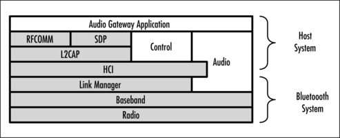
The only difference between the two routes through the system is that all packets passing through HCI experience some latency. The time taken for the Bluetooth subsystem’s microcontroller to transfer the audio data from the baseband into HCI packets introduces some delay, but this is imperceptible. However, there is a second factor that can cause severe delays and lead to loss of SCO packets: this is flow control of the HCI interface.
If the Universal Asynchronous Receiver Transmitter (UART) HCI transport is used, there is no way to separately flow control voice and data, so when data transport is flow controlled, the flow of voice packets across the HCI will also stop. Buffering in the baseband chip could be used to prevent loss of data, but in practice, since audio signals are time-sensitive, any late samples are simply discarded, leading to gaps in the audio signal. The problem does not arise if the USB transport is used for HCI, as this transport provides a separate channel for voice packets; however, USB requires complex drivers and is not appropriate for all products. To solve the problem of flow control affecting audio quality on serial links, the Bluetooth Special Interest Group (SIG)’s HCI working group is currently working on a new serial interface which will allow audio and data to be flow controlled separately.
Often, by the time the application developer gets involved, hardware choices have already been made—which means you really have no choice of audio interface, and must work within the limitations of what you have. However, if you are lucky enough to be involved in the choice early on, then in choosing a chip/chip set you should be aware of the potential impacts of choosing different interfaces to get audio into the Bluetooth subsystem. When you make a choice of silicon, be aware that not every chip/chip set supports audio, so obviously you need to work with a chip/chip set that does! Of those that do support audio, most provide direct access to the baseband. Some, however, do not support audio across HCI.
Selecting an Audio Profile
The Bluetooth specification is broken up into several parts. So far, we have looked at items covered by the Core Specification—this includes the radio baseband and the software layers which make up a Bluetooth protocol stack. The Core Specification has a second volume, which provides a series of profiles. The profiles give guidelines on how to use the Bluetooth protocol stack to implement different end-user applications.
The first version of the profiles document provides three different profiles covering audio applications: the Headset profile, the Cordless Telephony profile, and the Intercom profile. Within the Bluetooth SIG, there are working groups that are producing profiles to support further audio applications.
Many textbooks (such as Bluetooth: Connect Without Cables) will take you through the details of the profiles and protocol stack layers, and, of course, the Bluetooth specification itself provides the definitive guide to the subject. This section will just cover enough about the audio profiles to give you a taste of what’s involved. Use this information to decide which profiles may be appropriate for your application.
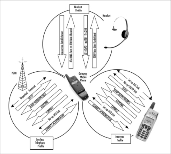
The first thing to be aware of is that your choice need not be limited to one particular profile. If your product supports several services, it may be appropriate to implement more than one profile. Figure 9.8 illustrates this point: it shows a 3-in-1 Bluetooth phone, which implements the Headset, Cordless Telephony, and Intercom profiles. Let us examine each of these profiles in turn.
The Headset profile allows the audio signal from a telephone call to be transferred between an audio gateway (AG) and a headset. A mobile phone is a typical audio gateway, but any device that receives incoming audio calls could be used. Similarly, the headset side is usually a headset with microphone and speaker, but it would be possible for a laptop computer to implement the Headset profile and use its microphone and speaker to handle the audio part of a telephone call.
The Headset profile uses AT commands across an RFCOMM connection for control. First, an ACL link is established and a connection to RFCOMM is set up. Then an AT+RING command is sent on the RFCOMM connection to trigger a ring tone in the headset. The user pushes a button on the headset to pick up the incoming call. The button push is signaled to the phone using an AT_CKPD (keypad command). Once the button press information is received, a SCO link can be set up to carry the voice call between the headset and the audio gateway.
The Cordless Telephony profile allows incoming calls to be transferred from a base-station to a telephone handset. In many ways, the Cordless Telephony profile provides similar capabilities to a digital enhanced cordless telecommunications (DECT) telephone system, except that it is not possible to hand over an active call to a different base station. This means that the phone handset must stay within range of a single base station. The Cordless Telephony profile provides control of information in addition to the transfer of audio, so, for instance, a calling line identifier (CLI) can be sent to the phone handset so the user can see who is calling them before deciding to answer the call.
The Intercom profile allows telephone calls to be transferred across a Bluetooth link without involving a telephone network at all. Again, identifying information can be sent with the call so that the receiver can display the number of the device initiating the call. There have been some questions about whether the Intercom profile is really useful (the lowest power Bluetooth devices only operate within a 10 meter range, and at these distances, you may as well shout). However, devices with class 1 radio modules can achieve 100m ranges, and this means that the Intercom profile could provide telephony services within an office building where it is not always appropriate to shout!
The Cordless Telephony and Intercom profiles both use Telephony Control Protocol (TCS) commands for control. The first stage is to establish an ACL link. Figure 9.8 shows two ways in which this can be done—the cordless telephony example shows a connection being unparked, while the intercom example shows a fresh connection being established. In both cases, the first step is to send a SETUP message to indicate a new call is being established. The SETUP message is acknowledged and the device receiving the call begins generating a ring tone to tell the user that a call is coming in. So that the device originating the call knows the user is being alerted, an ALERTING message is sent back by the device receiving the call. When the user accepts the call a CONNECT message is sent to the device originating the call, this triggers the setup of a SCO link. Once the SCO link is in place, the CONNECT message can be acknowledged.
While considering how different devices disconnect, it is worth thinking about one aspect of wireless connections which can trip up developers who are used to wired systems. Bluetooth is a wireless technology, and like other wireless technologies, it’s always possible the link will fail because of interference or because mobile devices move out of range of each other.
When the link fails, it will cause a link supervision timeout at the Link Management layer. This means that the Link Manager has detected that it has not been able to send packets on the link for a preset timeout period.
The default link supervision timeout on a Bluetooth link is 30 seconds, so by then the user will probably have given up and terminated the connection themselves. You could set the link supervision timeout period so that the link will automatically disconnect sooner than the default 30 seconds. To do this, you use the HCI Write_Link_Supervision_Timeout command. When the link disconnects, the HCI will return a Disconnection Complete event, and this should cause the various protocol stack layers to disconnect.
When the link does disconnect, your application will be notified. At this point, you will need to tidy up any resources in use by the link—free memory, close down audio channels, and so forth—just as if the call had been terminated by the user. If your device has a visual user interface, it is a good idea to display a message to the user informing them that the link has failed. If your device has an audio interface, you must decide whether to generate some tone to indicate the link has failed, or just leave the user listening to silence.
By now, you should be realizing that the Intercom and Cordless Telephony profiles are very similar in the ways they establish the link, whereas the Headset profile uses a completely different mechanism. This is because the Intercom and Cordless Telephony profile are controlling the link with TCS commands, while the Headset profile controls the link with AT commands. The different control mechanisms mean that when the profiles disconnect, we again see similarities between Intercom and Cordless Telephony, but the Headset profile still behaves differently.
Figure 9.9 shows how the Intercom and Cordless Telephony profiles share the same disconnection procedure. First of all, the party that is to end the call, sends a disconnect signal to the client that replied with a release permission and waits for the SCO link release signal to tidy up the resources and avoid memory leakage. The Headset profile is slightly different because it sends an AT-based keypad control (AT+CKPD) command to the audio gateway first, and the audio gateway releases both the SCO links and the connection.

It is interesting to note that the Headset profile does not provide any commands for the headset to terminate the connection; however, if the headset just drops the link, the audio gateway must be able to cope. So, if you wish to provide a disconnect facility for your users, then your code will be very simple: don’t send any commands, just disconnect!
Figures 9.8 and Figures 9.9 show example calls going in one direction. For the headset profile, the audio gateway side always initiates the call—the headset cannot initiate a voice call to the audio gateway, it can only accept an incoming call. With the Intercom and Cordless Telephony profiles, either device can initiate the call—so, for instance, with the cordless telephony profile, the base station can receive an incoming call from the PSTN and send that call to the phone handset, or the phone handset could initiate a call to the base station, and the base station would then pass that call out to the PSTN.
If you just want to transfer the audio part of a call without control information, then the Headset profile is small, simple, and definitely the one to use. If you need to initiate voice calls to other Bluetooth devices in the area, but are not passing them on to a network, then use the Intercom profile. If you are implementing a base station to pass voice calls to and from a telephone network, then you should use the Cordless Telephony profile.
Applications Not Covered by Profiles
You may have noticed that all of the three profiles previously described are oriented towards distributing telephony devices. All of these profiles use SCO links to carry the audio information. As we discussed earlier, that’s fine for telephones, but not so good if you need high-quality audio for music.
If your application provides a service which is covered by the existing Bluetooth profiles, then you should implement the relevant profile. However, at the moment, there are many possible audio applications which are not covered by profiles. If your application fits in this class, then you will have to design a complete proprietary application yourself without guidance from a profile document.
A disadvantage of producing your own proprietary application is that it will only work with other products that use the same control systems. That’s fine if you are implementing a closed system, but if you want to make some Bluetooth stereo headphones, then you’d probably prefer them to work with lots of different brands of stereos so that more people will buy them. The solution is to join in one of the working groups of the Bluetooth SIGs and get together with other manufacturers to come up with a profile that lots of devices can implement. To join a SIG working group, you must be an associate level member of the Bluetooth SIG (there is an annual fee for associate companies). Participating in a working group can also be quite time-consuming, often involving international travel to meetings, so this route will not suit everyone.
Another alternative is to look on the Bluetooth Web site and find out which working groups are producing new profiles. It may be that the profile you need is just around the corner. If that’s the case, it may be worth your while to wait for the profile to be released rather than go to all the trouble of developing a proprietary system only to discover that it fails in the market because everybody else is using a standardized profile.
New Audio Profiles
The Bluetooth SIG has working groups who are developing new profiles. There is a car working group, which is due to release a hands-free profile soon and an audio/visual (AV) group, which is working on a series of profiles to provide distribution of low bit rate video and high-quality audio.
The hands-free profile being produced by the car working group is targeted at in-car, hands-free kits, but could also be used in other applications, such as call centers. The hands-free profile will allow the hands-free device to initiate calls to the audio gateway. This will be done by transferring dialing information using AT commands across an RFCOMM serial link. Because the hands-free profile uses AT commands to dial, it will be simpler to implement than the TCS-based profiles.
The AV working group is providing a variety of profiles which will allow Bluetooth systems to support standardized audio and video capabilities. These provide videoconferencing capabilities—note that a video capability suitable for videoconferencing is probably not satisfactory for distributing video for entertainment purposes. In short, you won’t find this profile much good for watching movies! There is also an advanced audio distribution profile which supports higher quality audio than the basic SCO links. Distribution profiles provide standardized streaming channels to be set up and controlled to support audio or video distribution. There are also profiles defining how links should be controlled and how remote control should be provided.
In the future, more profiles will be released. Members of the Bluetooth SIG are notified by e-mail whenever new profiles become public.
Writing Audio Applications
In the previous section, we looked briefly at the various profiles available for audio applications. In this section, we’ll look in more detail at how a particular profile could be implemented at application level. We shall use the headset profile as our example application, because it is the simplest of the audio applications. Even then, much of the application functionality will remain the same whichever profile you use. For example, all inquiry, paging, scanning, and service discovery are the same no matter which profile you implement. Similarly, the audio must be routed into the Bluetooth subsystem somehow, regardless of the audio profile chosen.
As we explained in the previous section, the headset profile is used to transfer the audio part of a call between an audio gateway and a headset. Figure 9.10 shows some examples of devices that implement the Headset profile: the Ericsson DBA-10 snap-on Bluetooth accessory provides Bluetooth system capability to the Ericsson T28 world phone. The combined phone and accessory act as an audio gateway. The Ericsson and GN Netcom headsets both implement the headset part of the Headset profile.
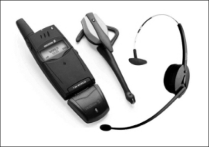
Figure 9.10 Bluetooth Devices that Use Audio Links (Ericsson Bluetooth Headset and Mobile Phone, GN Netcom GN9000 Headset)
Discovering Devices
Whichever audio profile is being supported, the initial steps in establishing a link will be similar. The first step will be finding suitable devices in your neighborhood using the Bluetooth Device Discovery procedures.
Chapters 1 and 2 explained how Inquiry and Inquiry Scan modes are used to implement device discovery. For audio applications, it is also worth noting that the inquiring device can use an HCI command to filter inquiry responses by device class. The Frequency Hopping Synchronization (FHS) packets used to respond to inquiries, each contain a major and minor device class. For the Headset profile, we are only interested in devices with the Class of Device set as follows:
![]()
The following pseudo-code shows how an application might implement device discovery:
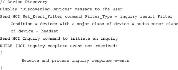
The exact code used will vary from system to system, but the procedure to set event filters, initiate an inquiry, and process the results until the inquiry completes, will remain the same. One possible variant would be to use periodic inquiry mode. This will set the lower layers to periodically perform an inquiry. Most audio applications will run on small battery-operated devices, and since periodic inquiries will drain the device’s batteries, their use is not recommended for audio applications.
Of course, the inquiry won’t get any results if there are no devices scanning, so to match the previous inquiry code, we need the inquiry scan pseudo-code that follows:

As explained in Chapters 1 and 2, the inquiry scan activity should be set according to the requirements of the Generic Access Profile. Again, because of the power drain caused by scans, it is recommended that a device should not be left in Inquiry Scan mode for long. This is why the previous code runs a timer, and when the timer causes a timeout, it disables the inquiry scan.
The fact that Inquiry and Inquiry Scan only happen for short periods implies that you must be able to trigger them somehow from the user interface. Usually, the audio gateway performs inquiries and the headset scans for them. If the audio gateway is a phone, an inquiry can be triggered through the phone’s menu system. A headset is more problematic since it will have a very limited user interface—buttons take up space and cost money, so you can’t have many of them! The Ericsson headset has a single button that is pressed to switch the headset on and off. If you keep the button held down after switching it on, you go into Inquiry mode. Experience shows that some users find interfaces that have many functions attached to one button difficult to operate, but you must balance this against the size, weight, and cost penalties of adding more controls onto the headset.
Using Service Discovery
Once the audio gateway application has found a device that belongs to the audio/headset class of devices, it needs to find out how to connect to the headset service. To do this, it uses Service Discovery Protocol (SDP) and performs a service search for the headset service.
The pseudo-code that follows illustrates the steps an audio gateway would go through when using service discovery on a headset.
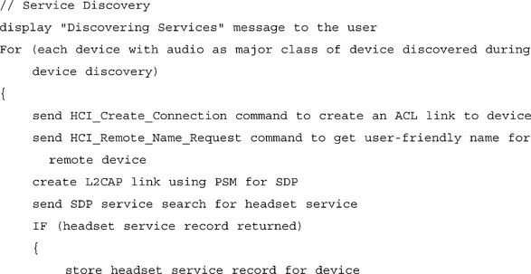

An ACL link is created, and once the link is up, a remote name request is used to find the user-friendly name of the remote device. This isn’t mandatory, but it will make your application a lot easier for users if you get this information for them.
A Logical Link Control and Adaptation Protocol (L2CAP) link is created across the ACL link. This must be created specifically for SDP, and uses a Protocol Service Multiplexor (PSM), which tells the remote device to connect the L2CAP link to its SDP server. Once the L2CAP link is established, it can be used to send SDP service search requests to retrieve the service record for the headset service. This record confirms that the remote device implements the headset profile, and gives version information, along with information required to connect to the headset service.
Once the service record is returned, it can be stored locally so that if the device is encountered in future service discovery, it does not have to be performed again. Any new information can also be displayed to the user, and as the link is now finished, it may be destroyed.
Leaving the link up wastes power, but establishing a link also takes up power, so there is a decision to be made about disconnecting links. In the preceding example, the L2CAP and ACL links were both disconnected, but there is a chance that the ACL link will be reused to connect to the headset service. This means that it might be advisable to wait a while before disconnecting the ACL link. Because of this, you might implement something like this:
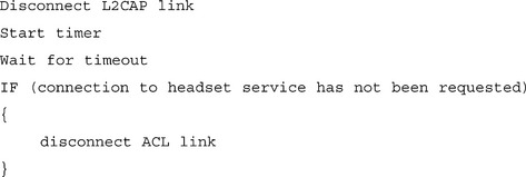
The L2CAP link is disconnected straight away because it was created with a PSM value for SDP. This means that the L2CAP link cannot be used for anything other than service discovery.
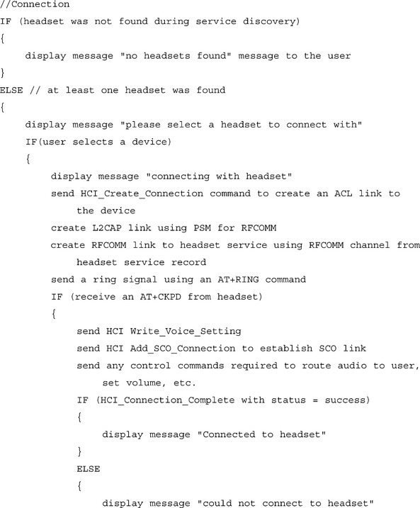
Connecting to a Service
Now we can finally get to the whole point of the application and connect to an audio service. The first step is to set up an ACL link—this could be a link leftover from the service discovery phase, or if that link was disconnected, it could be a new link set up by repeating the paging process. This connection is used to create an L2CAP link using the PSM value for RFCOMM. Next, an RFCOMM channel is set up to control the headset. The Channel ID for the headset was provided to the Audio Gateway in the headset’s service record.
The RFCOMM connection is used to send the AT commands which control the headset service. The first command shown in the following is an AT+RING signal, which tells the headset to produce a ring tone. This ring tone alerts the user that a call is coming from the audio gateway.
The user should somehow accept the call—this could be done with a voice recognition system, but it will most likely be done by the user pressing a button on the headset. However, the user actually accepts the call with the keypad signal AT+CKPD, which is sent back to the audio gateway across the RFCOMM channel.
Now that the audio gateway knows the headset is willing to accept the call, it establishes an audio (SCO) link. This could optionally have been done earlier on, but audio links consume power, so it is better to wait until the last possible moment to set up the SCO link. The link must be configured, and our example shows an HCI Write_Voice_Setting command which sets the Codec format (A-law or μ-law PCMs and CVSD). The Codec does not have to be chosen at this point—this could have been set earlier on, or left at some default value. Once the Codec settings are configured as required, a SCO connection can be set up using the HCI Add_SCO_Connection command. The parameters for this command specify the connection handle of the ACL connection across which the SCO connection will be set up, as well as the packet type to be used on the SCO connection (HV1, HV2, and HV3).
Note that the audio gateway initiates the SCO connection, which means it chooses the Codec and HV packet type to be used on the link. Because the audio gateway chooses the Codec and packet type, the headset must be able to accept all Codecs and packet types. However, because the headset does not need to worry about deciding which type is appropriate, the headset application is much simpler to write.
Immediately after the Add_SCO_Connection, an HCI_Command_Status event is returned to acknowledge the command. When the SCO connection is established, an HCI_Connection_Complete event is received. If there were any problems with the connection, the status field will carry a reason for failure. The following pseudo-code illustrates this procedure.
This example is simplified and does not cover security procedures. For an in-depth look at security, see Chapter 4. It is worth noting in passing, however, that a headset can be paired to the audio gateway, and it is possible to pair a headset with more than one device. If this was done, then the same headset could quickly and easily be used with a variety of audio gateways. For instance, while on the move, you could use your headset with a mobile phone, but in the office, the same headset might be used with a Bluetooth-enabled desk phone.
Using Power Saving with Audio Connections
Some of the Bluetooth-audio enabled devices might have very small batteries, because of both size and weight constraints, so optimizing power consumption is important. Sometimes an audio device will be idle for a long time—for example, after terminating the communications link or while waiting for an audio connection to be established. During these idle periods, it doesn’t need to participate in the channel. We could simply drop the ACL connection, but then when we needed to connect with it again, there would be a delay. For a cellular phone headset, it could be a real disadvantage to have to wait a few seconds while the phone paged the headset. This would introduce an unacceptable delay in notifying the user that a call is coming in. So, to allow fast audio connections to be made, we want to keep the ACL link, but to save power, we want to drop the link.
The solution is to use the low-power park mode. In this mode, the Bluetooth-enabled audio device remains frequency-hop synchronized by waking up periodically during beacon slots to resynchronize with the master. The master can use beacon slots to reactivate the device, so that when an incoming call arrives, the terminal can be unparked fast enough to answer the call or can start to listen to the music from the beginning of the play. The spacing of the beacons is a trade-off between response times and power saving. Long beacon intervals give a slow response, but require less activity from both master and parked slave. Short beacon intervals give faster response, but require more activity and hence consume more power. See Chapters 1 and 3 for more details on low-power modes.
Differentiating Your Audio Application
So far, we’ve looked at the basics of writing a Bluetooth audio application, but if you’re making a product to sell, you don’t want a basic application, you want something special! This section will look at a few of the ways you can differentiate your audio application, adding value for the user. This is the sort of thing you need to do if you want your product to sell better than the next guy’s.
Physical Design
Chapter 1 looked at some of the physical factors that make a Bluetooth product succeed, so we won’t go into great detail here. But do be sure not to forget the weight, size, and form factor. All of this may be beyond your control, but if you are involved in the original product design, you can contribute to your devices salability by ensuring that these are thought about.
Bluetooth wireless technology is still young. The people buying Bluetooth audio devices today are the classic early adopters—gadget freaks who are willing to take a risk just to have the latest thing. Something that displays the novelty of the device can be quite an important factor—blue LEDs are much more expensive than red or green, but look around and you’ll find plenty of Bluetooth products sporting blue flashing LEDs. The reason is that displaying their new technological gadget is an important factor to the early adopters, and that blue LED says “my product is a Bluetooth product.” Thinking about apparently trivial items like the color of an LED can be the difference that makes your design stand out and appeal to your target users.
Designing the User Interface
The user interface is the one aspect of your application that has the power to make or break your market success. The qualification process ensures that you’ve got the technology right, but nobody will stand over you and make sure your product is actually usable! As you write your application, ask yourself if there are ways to hide the complexity of Bluetooth technology.
The profiles constrain what you can do with an application—this is done with good reason: it helps to ensure that products from different manufacturers will interoperate. You might think that if everybody’s application is implementing the same profile, there is no real scope for differentiating products at the user interface level. Don’t despair—there are plenty of things you can do to make sure your application has an edge over the competition.
Many headsets are using a single function button, which is slid from side to side for volume up/down and pressed for various lengths of time to perform other functions. You should balance the complexity of such an interface with the cost and added size involved in having more buttons. What works best will differ from product to product, so think about what works best for your form factor.
One factor that is often overlooked in headset design is the possibility of using the audio channel as part of the user interface. Even systems that do not implement voice recognition can quite simply and easily use the audio path as part of the user interface by generating tones to inform the user of events. For example, if a call is disconnected due to link loss, a continuous tone could be sounded for half a second alerting the user that there is a problem. Similarly, if the device has a low battery, a series of tones could be sounded to warn the user that they are about to lose usage of the device. Because the user interfaces are very limited on small mobile audio devices, it is worth considering whether your application can make use of the device’s built-in audio facilities to provide a richer user interface.
Enabling Upgrades
One way to differentiate your product is to provide ongoing support for new features, or for future versions of the Bluetooth specification. More and more devices are now providing upgrade facilities for users. If you choose to do this, then you will have to consider how to avoid the upgrade process being run accidentally. This is important because the first stage of a device upgrade often involves wiping code and leaving the device in an unusable state if there is no upgrade code available.
Once you have an interface to start the upgrade process, you will need to consider the route by which you can download code to upgrade to a new version or to add features. Some part of the system will need to check the code to be sure it is a correct authorized version. A checksum should be implemented to ensure the new code is not corrupt, and you may like to also consider incorporating a security code to avoid unauthorized or accidental modification of your device’s application.
Many devices are capable of being upgraded, but with the exception of PC applications, it could be argued that very few users ever choose to take advantage of upgrade facilities. However, just because devices installed in the field may not be upgraded, it does not mean that upgrades are not relevant to your application. Often, devices awaiting shipment require an upgrade before delivery; if this might apply to your products, then it is worthwhile providing some route for upgrades to be downloaded to your device. Manufacturers who upgrade old stock awaiting shipment may choose to enable upgrades using special commands which are not publicized to the end users. In this way, they can hide a complex engineering interface from the user’s eyes, and prevent accidental use of the upgrade interface.
Improving the Audio Path
As mobile devices become ever smaller, design problems start to appear, particularly with duplex voice systems. In a wired headset, the microphone typically dangles on a flexible cord and is quite well separated from the earpiece. Bluetooth headsets tend to be designed to clip on the ear with the microphone carried on a small boom, which places it close to the user’s mouth. This creates two problems: first, the microphone and earpiece are physically closer together, creating the possibility of an audio feedback loop through free space, and second, their linking by the rigid boom creates the potential for acoustic coupling between the microphone and earpiece through the casing of the headset itself.
There can also be resonance effects within the components of devices—rigid cases and printed circuit boards (PCBs) can resonate at particular frequencies, and it is also possible for the coupling between the audio gateway and the headset to affect the audio. Combine all these effects and there can be noticeable impacts on the audio quality perceived by the user.
The primary solution will always lie in good physical design of the product, but there are other things that can be done. Most mobile phones incorporate echo canceling and other such advanced techniques, which use the digital processing power of the phone to reduce unwanted components in the audio signal. Digital signal processing, of course, uses processing time, adding expense and increasing power consumption, so it should only be used in a headset as a last resort.
Summary
Bluetooth wireless technology has a promising future in the mobile phone and handheld devices’ audio markets. We have seen that Bluetooth devices can support up to three full-duplex SCO audio channels, or support up to two voice channels with simultaneous data transfer. Those channels use three coding schemes: CVSD, μ-law PCM, and A-law PCM. CVSD is more robust for errors and can support higher quality over good links. However, PCM is cheap and already available in a lot of commercial devices. For maximum compatibility, we really need both.
There are two routes for audio into the Bluetooth system: straight into the baseband or through HCI. The HCI route can experience latency due to flow control of data between host and lower layers. The Bluetooth SCO links provide toll-quality voice suitable for carrying phone calls. For high-quality audio (such as that required for music), the SCO links do not provide sufficient quality. Currently, there is no standardized way of providing high-quality audio across Bluetooth links, but compressed audio (such as MP3) could be sent across an asymmetric ACL link.
There are three audio profiles: Headset, Intercom, and Cordless Telephony. Further profiles are being defined, including those that provide higher quality audio across Bluetooth links. The steps involved in using an audio service are common to all profiles—discover devices perform service discovery, exchange control information, and configure and set up an audio link.
Audio applications can be differentiated in many ways. We considered physical design, user interface design, enabling upgrades, and improving the audio path.
Solutions Fast Track
![]() Codecs (coder/decoders) convert between analog voice samples and the compressed digital format.
Codecs (coder/decoders) convert between analog voice samples and the compressed digital format.
![]() The output of the Codecs must be fed into the Bluetooth baseband as a direct input to the baseband (a technique commonly used in Bluetooth chips), or encapsulated in a Host Controller Interface (HCI) packet and fed across the Host Controller Interface.
The output of the Codecs must be fed into the Bluetooth baseband as a direct input to the baseband (a technique commonly used in Bluetooth chips), or encapsulated in a Host Controller Interface (HCI) packet and fed across the Host Controller Interface.
![]() Bluetooth technology uses CVSD and PCM Codecs. CVSD is more robust in the presence of errors, which is what makes CVSD attractive for use in Bluetooth systems. PCM is cheap and already available in many commercial devices.
Bluetooth technology uses CVSD and PCM Codecs. CVSD is more robust in the presence of errors, which is what makes CVSD attractive for use in Bluetooth systems. PCM is cheap and already available in many commercial devices.
![]() There are two types of compression implemented in PCM Codecs: A-law and μ-law. The different types are used by phones in various geographical regions.
There are two types of compression implemented in PCM Codecs: A-law and μ-law. The different types are used by phones in various geographical regions.
Configuring Voice Links
![]() The Bluetooth system transmits data on ACL links and voice on SCO links. SCO links use periodically reserved slots, while ACL links do not reserve slots.
The Bluetooth system transmits data on ACL links and voice on SCO links. SCO links use periodically reserved slots, while ACL links do not reserve slots.
![]() Live audio needs circuit switched channels to guarantee regular delivery of voice information—the receive Codecs need a regular feed of information to provide a good quality output signal. The circuit switched channels are the Synchronous Connection-Oriented links. They occupy fixed slots that are assigned by the master when the link is first set up.
Live audio needs circuit switched channels to guarantee regular delivery of voice information—the receive Codecs need a regular feed of information to provide a good quality output signal. The circuit switched channels are the Synchronous Connection-Oriented links. They occupy fixed slots that are assigned by the master when the link is first set up.
![]() Always remember that Bluetooth technology maintains a maximum of 3 × 64 Kbps full-duplex SCO voice packets. The SCO links provide voice quality similar to a mobile phone; if higher audio quality is desired, then compressed audio must be sent across ACL links.
Always remember that Bluetooth technology maintains a maximum of 3 × 64 Kbps full-duplex SCO voice packets. The SCO links provide voice quality similar to a mobile phone; if higher audio quality is desired, then compressed audio must be sent across ACL links.
![]() Notice that we don’t want to modify the voice packets at the L2CAP layer. SCO packets bypass the L2CAP layer.
Notice that we don’t want to modify the voice packets at the L2CAP layer. SCO packets bypass the L2CAP layer.
![]() If you choose to send data at the same time as voice, you will also lose out on error protection on the voice links.
If you choose to send data at the same time as voice, you will also lose out on error protection on the voice links.
![]() When a link is to be established, use the following procedure: scan or page for an audio device. Use SDP to identify service. Set up ACL connection first for control, then set up SCO connection. During a voice connection, control messages can be sent such as DTMF signals
When a link is to be established, use the following procedure: scan or page for an audio device. Use SDP to identify service. Set up ACL connection first for control, then set up SCO connection. During a voice connection, control messages can be sent such as DTMF signals
Choosing an Audio Interface
![]() There are two routes for audio: either a direct link between the baseband and the application layer, or through the HCI. All packets passing through HCI experience some latency.
There are two routes for audio: either a direct link between the baseband and the application layer, or through the HCI. All packets passing through HCI experience some latency.
![]() If the Universal Asynchronous Receiver Transmitter (UART) HCI transport is used, there is no way to separately flow control voice and data, so when data transport is flow controlled, the flow of voice packets across the HCI will also stop. The USB transport provides a separate channel for voice packets; however, USB requires complex drivers.
If the Universal Asynchronous Receiver Transmitter (UART) HCI transport is used, there is no way to separately flow control voice and data, so when data transport is flow controlled, the flow of voice packets across the HCI will also stop. The USB transport provides a separate channel for voice packets; however, USB requires complex drivers.
![]() Not every chip/chip set supports audio. Of those that do, most provide direct access to the baseband, but some do not support audio across HCI.
Not every chip/chip set supports audio. Of those that do, most provide direct access to the baseband, but some do not support audio across HCI.
Selecting an Audio Profile
![]() Three different profiles cover audio applications: the Headset profile, the Cordless Telephony profile, and the Intercom profile. If your product supports several services, it may be appropriate to implement more than one profile. If your application is not covered by one of the profiles, you will have to design a complete proprietary application yourself.
Three different profiles cover audio applications: the Headset profile, the Cordless Telephony profile, and the Intercom profile. If your product supports several services, it may be appropriate to implement more than one profile. If your application is not covered by one of the profiles, you will have to design a complete proprietary application yourself.
![]() The Headset profile allows the audio signal from a telephone call to be transferred between an audio gateway (AG) and a headset. If you just want to transfer the audio part of a call without control information, then the Headset profile is small, simple, and definitely the one to use.
The Headset profile allows the audio signal from a telephone call to be transferred between an audio gateway (AG) and a headset. If you just want to transfer the audio part of a call without control information, then the Headset profile is small, simple, and definitely the one to use.
![]() The Cordless Telephony profile allows incoming calls to be transferred from a base-station to a telephone handset. If you are implementing a base station to pass voice calls to and from a telephone network, then you should use the Cordless Telephony profile.
The Cordless Telephony profile allows incoming calls to be transferred from a base-station to a telephone handset. If you are implementing a base station to pass voice calls to and from a telephone network, then you should use the Cordless Telephony profile.
![]() The Intercom profile allows telephone calls to be transferred across a Bluetooth link without involving a telephone network at all. If you need to initiate voice calls to other Bluetooth devices in the area, but are not passing them on to a network, then you should use the intercom profile.
The Intercom profile allows telephone calls to be transferred across a Bluetooth link without involving a telephone network at all. If you need to initiate voice calls to other Bluetooth devices in the area, but are not passing them on to a network, then you should use the intercom profile.
![]() The Cordless Telephony and Intercom profiles both use Telephony Control Protocol (TCS) commands for control and share the same disconnection procedure. The Headset profile controls the link with AT commands, and does not provide any commands for the headset to terminate the connection.
The Cordless Telephony and Intercom profiles both use Telephony Control Protocol (TCS) commands for control and share the same disconnection procedure. The Headset profile controls the link with AT commands, and does not provide any commands for the headset to terminate the connection.
Writing Audio Applications
![]() In this section, we looked in detail at how a particular profile could be implemented at application level. All inquiry, paging, scanning, and service discovery are the same no matter which profile you implement. Similarly, the audio must be routed into the Bluetooth subsystem somehow, regardless of the audio profile chosen.
In this section, we looked in detail at how a particular profile could be implemented at application level. All inquiry, paging, scanning, and service discovery are the same no matter which profile you implement. Similarly, the audio must be routed into the Bluetooth subsystem somehow, regardless of the audio profile chosen.
![]() The first step will be finding suitable devices in your neighborhood using the Bluetooth Device Discovery procedures.
The first step will be finding suitable devices in your neighborhood using the Bluetooth Device Discovery procedures.
![]() Once the audio gateway application has found a device that belongs to the audio/headset class of devices, it needs to find out how to connect to the headset service. To do this, it uses Service Discovery Protocol (SDP) and performs a service search for the headset service.
Once the audio gateway application has found a device that belongs to the audio/headset class of devices, it needs to find out how to connect to the headset service. To do this, it uses Service Discovery Protocol (SDP) and performs a service search for the headset service.
![]() Once the service discovery phase is complete, you can connect to an audio service. The first step is to set up an ACL link. This connection is used to create an L2CAP link using the PSM value for RFCOMM. Next, an RFCOMM channel is set up to control the headset. Once the audio gateway knows that the headset is willing to accept the call, it establishes an audio (SCO) link. The headset must be able to accept all Codecs and all packet types on the link.
Once the service discovery phase is complete, you can connect to an audio service. The first step is to set up an ACL link. This connection is used to create an L2CAP link using the PSM value for RFCOMM. Next, an RFCOMM channel is set up to control the headset. Once the audio gateway knows that the headset is willing to accept the call, it establishes an audio (SCO) link. The headset must be able to accept all Codecs and all packet types on the link.
Differentiating Your Audio Application
![]() Be sure to consider the weight, size, and form factor in your product design.
Be sure to consider the weight, size, and form factor in your product design.
![]() The user interface is the most crucial aspect of your application. Ask yourself if there are ways to hide the complexity of Bluetooth technology. Button functions and headset designs offer opportunities for improvement and differentiation.
The user interface is the most crucial aspect of your application. Ask yourself if there are ways to hide the complexity of Bluetooth technology. Button functions and headset designs offer opportunities for improvement and differentiation.
![]() Another way to differentiate your product is to provide ongoing support for new features or for future versions of the Bluetooth specification.
Another way to differentiate your product is to provide ongoing support for new features or for future versions of the Bluetooth specification.
![]() Improving design and engineering to better the audio path can have a noticeable impact for the user, helping to avoid audio feedback, acoustic coupling, and resonance effects.
Improving design and engineering to better the audio path can have a noticeable impact for the user, helping to avoid audio feedback, acoustic coupling, and resonance effects.
Frequently Asked Questions
The following Frequently Asked Questions, answered by the authors of this book, are designed to both measure your understanding of the concepts presented in this chapter and to assist you with real-life implementation of these concepts. To have your questions about this chapter answered by the author, browse to www.syngress.com/solutions and click on the “Ask the Author” form.
Q: The input to the CVSD encoder is 64 K samples/s linear PCM. How can you create the 64 Kbps encoder output using just using an 8 K samples/s input?
A: It is 64 Kbps but 8 K samples/s. If there are 8 quantization levels per sample, this is the same as saying 64 Kbps. It all depends on the number of distinct levels the sample can represent.
Q: If a Bluetooth SCO link can’t carry CD-quality sound, how could you develop a Bluetooth-enabled MP3 player?
A: It is possible, but we have to use ACL channel (maximum asymmetric data rate 732.2 Kbps) audio sent in compressed format, and buffering must be done to allow a constant flow of data to the MP3 decoder, despite delays caused by retransmissions on the ACL link.
Q: Why is CVSD more robust for errors than PCM?
A: First of all, CVSD requires a 1-bit sample length compared to the 8-bits used in PCM, so more samples can be sent in the same bandwidth. Second, since CVSD is a differential scheme and depends on the slope between the symbols (unlike PCM), when the data is corrupted, the effect is less marked, as the signal only has a small difference from the correct signal. Third, the CVSD algorithm incorporates a decay factor, which means that upon receipt of correct data, the output signal will tend towards the correct value.