
Introducing Bluetooth Applications
Introduction
As human beings, we accept without question that we have the ability to communicate, that if we speak or write according to a pre-defined set of linguistic rules that we will succeed in conveying information to one another. The tools of human communication, producing sounds that are perceived as speech or creating words on a page, once learnt are used without thought. The limitation on these physical processes that we take for granted is the actual translation of thoughts into effective and meaningful statements. When it comes to electronic communication, however, there is very little that can be assumed or taken for granted. Communication between electronic devices can only be achieved when they also abide by a set of predetermined rules and standards—the Open Systems Interconnect (OSI) model for communications systems protocol stacks being the primary example, and the basis from which many others have evolved.
These standards need to be applied to every aspect of the communication process, from the manipulation of data at the highest level to the utilization of physical transmission media at the lowest. Electronic communication has evolved significantly over the last decade from the earliest packet switched data networks (PSDNs) and the Xerox, Ethernet, and IBM Token Ring local area network (LAN) technologies, to the now common-place mobile telephony and dedicated high-speed data communication. (How would we survive without e-mail and the WWW?)
New technologies are now emerging that allow wireless communication. The IEEE 802.11b or Wi-Fi standard is becoming accepted as the choice for the networking community as it supports features that enable it to perform handovers between access points, and it can effectively become a transparent wireless network, expanding the static wired network. IEEE 802.11b has a data throughput of up to 11 Mbps, which gives it viability against wired networks. This is evolving further with the advent of IEEE 802.11a and its competitor HyperLAN2 with even greater data rates. This technology is expensive and therefore not compatible with price-conscious consumer products, but we have now been provided with the means to create wireless, low-power, cost-effective, unconscious and ad-hoc connectivity between our devices. Its name: Bluetooth. If we believe all of the hype surrounding Bluetooth technology, we can expect our fridge to use our mobile phone to order groceries over the Internet, and, of course, end up ordering an extremely expensive new car instead of a steak! Yes, we have all seen the jokes, but in reality we can utilize this technology now to develop products that will allow us to throw away all the wires—and communicate without cables.
Excellent, we all think, and our imagination races into the realms of Science Fiction, removing the wires from everything! Musing on using our mobile phone to communicate and control everything the same way we use the TV remote to operate our entertainment systems.
This is a book for engineers in the real world, so let’s take a long hard look at what Bluetooth technology really does offer. For some applications, Bluetooth technology delivers the dream of convenient wireless connectivity. For other applications, however, it just isn’t the right answer. You do not want to spend a lot of time and effort learning about Bluetooth technology only to realize it isn’t for you, so we are going to start out by analyzing what the features of a really good Bluetooth product are. If your application does not fit into the Bluetooth scheme of things, you can put the book down after this chapter and go and look elsewhere.
If you make it past this chapter, you can be confident Bluetooth technology is right for you. There will still be quite a few make or break pitfalls before you have a killer application, but they are minor issues compared to choosing the wrong technology.
Why Throw Away Wires?
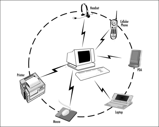
Wired or wireless? Let’s examine just why we’d want to connect without wires, and what it might offer us in tangible terms; we can use the paradigm of our own personal area network (PAN). We have a PC with its ubiquitous mouse and keyboard, a laptop, a personal digital assistant (PDA), a mobile phone with a “hands free” kit and a printer. How do we currently communicate between these devices? The answer is: with a rather unwieldy network of cables, hubs, and connectors—plugging, unplugging, and synchronizing often with the compulsory intervention of the overworked and often less-than-friendly IT department!
In the wired solution scenario that we are all accustomed to, all of the mobile devices are used in the singular—the interaction between them is always user-initiated. We generally keep our contacts’ addresses in our PCs or laptops, while their phone numbers also need to be entered into our mobile phone’s directory. We are effectively forced to become database managers simply in order to maintain an up-to-date record of our contact’s details. We connect to our company LAN via user-initiated password entry and connect to a printer only if we have already installed the driver or have administrator rights on our PC’s—nothing is unconscious.
Figure 1.1 illustrates the alternative scenario—to Bluetooth-enable all of these devices. The simple act of utilizing Bluetooth technology as cable replacement removes the problem of the actual physical connections and the unconscious and ad-hoc connection capability of the technology can allow communication between the devices with no user intervention at all (OK, after some software configuration and initial device setup!).
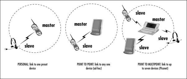
This fully wireless scenario can be achieved because of the master/slave nature of the Bluetooth technology. All devices are peers, identified by their own unique 48-bit address, and can be assigned as a master either by function or user intervention. A master can connect to up to seven slaves at the same time, forming a piconet—this “point-to-multipoint” feature is what sets Bluetooth apart from other wireless technologies. Figure 1.2 illustrates several connection scenarios.
In the ultimate scenario, a member of one piconet can also belong to another piconet. Figure 1.3 illustrates the scatternet, wherein a slave in one piconet is also the master of a second piconet—thus extending the networking between devices. A device in my PAN can communicate with one in yours!

Let us put this into context by interpreting exactly what “unconscious and ad-hoc connections” can mean to us in real life, and how the fundamental components of the Bluetooth PAN in Figure 1.1 can be integrated into a wireless infrastructure to enhance our lives and even reduce the need to queue!
Adding Usability to Products
Mr. I.M. Wireless is embarking on a business trip. At the airport, as he gets within range of the airline’s counter, his reservation is confirmed and a message is sent to his mobile phone detailing flight confirmation, personal boarding reference, seat information and departure gate number, which he listens to via a headset being that his phone is actually in his briefcase. While in the departure lounge, he connects to the Internet and accesses his e-mail via his mobile phone or the wireless LAN Access Point fitted in the lounge. He boards his flight and during the journey composes e-mails which will be sent as he enters the range of a LAN in the arrivals lounge or again via his mobile phone. He walks to the rental car company’s counter to pick up his keys—as with the airline, all booking, payment, and car location details would have been transmitted between his PDA/mobile telephone and the rental company’s computer. He starts to drive the rental car and his PDA downloads his hotel information into the car’s on-board systems, which allows the navigation system to smoothly direct him to its location. On arrival, his room booking reservation is already confirmed. At his meeting, the normal 15-minute exchange of business cards is removed as all of the personal information is exchanged automatically via his PDA. He then uses his PDA to run his presentation from his laptop, which all attendees at the meeting are viewing simultaneously on their own laptops. Back in his hotel room after the meeting, his PDA synchronizes with both his laptop and mobile phone—now the telephone details of all the new contacts he met are stored in his mobile phone directory and the address and e-mail information in his laptop. Later, while relaxing, he listens to MP3 files stored on his laptop with the same headset that he answers his phone with. He also uses his digital camera to send “an instant postcard” via his mobile phone and the Internet to his wife’s PC at home (obviously, it won’t be a picture from the Karaoke evening arranged by his clients!)
If we extract some conclusions from this slightly excessive example, we find that wireless connectivity offers us immense freedom and convenience. It allows us to perform tedious tasks with a minimum of intervention, allows some of our devices to have dual functionality, and makes the vast array of cables we inevitably always leave in the office redundant. Bluetooth technology “will” change the assumptions we all have about our electronic devices. With the cables gone, the idea of having a particular gadget for a specific job will no longer be relevant. With many of the devices already available to consumers, this scenario grows closer to reality every day.
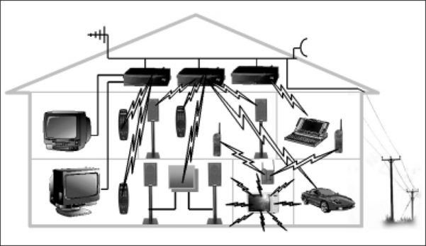
As for networking our homes, there are two ideologies. The first predicts a “master device” that will control everything from the video recorder to the security system, and which will replace the PC as the technological hub of the home. The other suggests the PC will remain at the centre of a networked home. Figure 1.4 illustrates how the PAN can be extended in our homes and combined with our wired infrastructure to provide a home area network (HAN) that utilizes wireless technologies for audiovisual (AV) control and distribution. The British mobile telephone company Orange is currently promoting a wireless house that will demonstrate various technologies in a “real-world” environment. More information can be found on the Orange Web site at www.orange.co.uk.
Allowing for Interference
Wireless means a radio link—and radio links are subject to interference. Interference can impact both the quality of an audio (Synchronous Connection Oriented [SCO]) connection or the throughput of a data (Asynchronous Connectionless [ACL]) connection. High levels of interference can interrupt communications for long enough to cause the protocol stack to timeout and abandon the link altogether. Although this is addressed in the Bluetooth Specification with a frequency-hopping scheme which does provide robustness, it is still a serious consideration for some applications.
Bluetooth technology should not be used for safety-critical applications where data absolutely must get through, because there is always a possibility of a burst of interference stopping the link. Interference can come from a variety of sources: microwave ovens, thunderstorms, other communications systems (such as IEEE 802.11b), even other Bluetooth devices in the area (although these will not have a great effect as they are designed to cope with interference from one another in normal use).
It is possible to overcome the problem of link failure. For example, if you are relying on a Bluetooth link to monitor your baby and you know the environment is such that the link will only fail approximately once a week, then you might be happy to have the receiver alert you when the link fails. Once a week you may be out of touch, but an alert will let you know that the link has failed, so you have the option of returning within earshot of the infant. Since the Bluetooth links only operate up to around 100 meters, it shouldn’t take you too long to get there!
There are other safety-critical applications where an unreliable link may be acceptable. An example is a system developed for Nokian tires, which allows tire pressure to be automatically monitored and sent to the car dashboard display. A wireless link will be subject to frequent failures in the harsh automotive environment, but the link can be re-established. Even if it only works a tenth of the time, it is still checking tire pressures far more often than will the average motorist! Here again, the system could be set to alert the driver if the tire pressures have not been reported recently. This way the driver knows that a manual check is needed.
So far, we have looked at effects of the Bluetooth link receiving interference, but, of course, it can also interfere with other devices. Bluetooth devices are obviously completely unsuitable for use in an environment where the Bluetooth link would interfere with sensitive control equipment—an aircraft being the primary example. Interference issues are explained in more depth later in this chapter.
Considering Connection Times
With a radio link, although the connections can be unconscious, connection times can be lengthy as transmitters and receivers all need to synchronize before communication can commence. These limitations could have serious consequences if the wireless link was of a critical nature—for example, a “panic button,” a life-dependant medical monitor, or an engine management system.
There are two delays in setting up a Bluetooth link. First, it takes time to discover devices in the neighborhood. In device discovery, a device sends out inquiry packets, and receives responses from devices in the area, then reports these to the user. It can take ten seconds to find all the devices in an area, and even then you will only find those devices which are willing to report their presence. Some devices may not be set to scan for inquiries, in which case you will never find them!
A second delay occurs when you set up the connection itself. Again, this can take up to ten seconds. This lengthy connection time means that Bluetooth devices are unsuitable for systems where a fast response is needed, such as automatic toll collection on busy roads.
Coping with Limited Bandwidth
Wireless can also mean “slower.” An Internet connection via a Bluetooth LAN is limited to the maximum data rate (723.2 Kbps) over the air interface. After allowing for management traffic and the capacity taken up by headers for the various protocol layers, even less is available to applications at the top of the stack. This will not compete with a high-speed wired link. Thus, for sending or downloading vast amounts of data, a Bluetooth wireless connection would not be the optimum method.
This also impacts on audio quality: Bluetooth technology simply does not have the bandwidth for raw CD quality sound (1411.2 Kbps). However, if a suitable compression technique is employed (using MP3 to compress an audio stream down to 128 Kbps, for example), it is feasible to use an ACL link for high-quality audio. The quality of a Bluetooth SCO link is certainly not high quality—it is approximately equivalent to a GSM telephone audio link (64 Kbps).
Compression can be useful for data devices. If large amounts of data are to be sent, using a compressed format will obviously speed up transfer time.
Considering Power and Range
Power is a critical consideration for wireless devices. If a product is to be made wireless, unleashed from its wired connection, where will its power come from? Often the communication cable also acts as a power cable. With the cable gone, the subject of batteries is brought into focus, and the inevitable questions arise concerning battery life, standby time, and physical dimensions.
Some devices, such as headsets, have no need for power when they are connected with wires. Audio signals come down a wire and drive speakers directly; a very simple system with no need of extra power connections. When the wires are replaced with a Bluetooth link, suddenly we need power to drive the link, power to drive the microprocessor that runs the Bluetooth protocol stack, and power to amplify the audio signal to a level the user can hear. With small mobile devices you obviously do not want to install huge batteries, so keeping the power consumption low is an important consideration.
Deciding on Acceptable Range
The Bluetooth specification defines three power classes for radio transmitters with an output power of 1 mW, 2.5 mW and 100 mW. The output power defines the range that the device is able to cover and thus the functionality of your product must be considered when deciding which power class to use. The user would not want to have to get up from his desk to connect to the LAN and therefore requires a higher power radio. Conversely, a cellular phone headset is likely to be kept close to the phone, making a lower range acceptable, which allows smaller batteries and a more compact design. Table 1.1 details the respective maximum output power versus range.
Table 1.1
| Power Class | Max Output Power | Range |
| Class 1 | 100 mW | 100 meters + |
| Class 2 | 2.5 mW | 10 meters |
| Class 3 | 1 mW | 1 meter |
It is important to realize that the range figures are for typical use. In the middle of the Cambridgeshire fens, where the land is flat and there is not much interference, a Class 1 device has been successfully tested at over a mile. But in a crowded office with many metal desks and a lot of people, the Bluetooth signal will be blocked and absorbed, so propagation conditions are far worse and ranges will be reduced.
Recognizing Candidate Bluetooth Products
Taking into account the preceding sections, we can see that for a product to be a candidate for Bluetooth technology, it needs to adhere to the six loosely defined conditions that follow:
![]() Adds usability (that is, convenience and ease-of-use—the Bluetooth Dream!)
Adds usability (that is, convenience and ease-of-use—the Bluetooth Dream!)
![]() Interference or latency will not affect its primary function
Interference or latency will not affect its primary function
![]() Is tolerant to the connection time overhead
Is tolerant to the connection time overhead
![]() Can afford the limited Bluetooth bandwidth
Can afford the limited Bluetooth bandwidth
The remainder of this chapter will explore these issues in depth to attempt to provide an insight into what actually “does” make a good candidate for the Bluetooth technology. It will also present a case for the various implementation techniques available to the developer with their inherent advantages and limitations.
Considering Product Design
Your product may look like a candidate Bluetooth product, but there are practical considerations to take into account. It costs money to add a Bluetooth link, and for some products, that cost may be more than the customer is willing to pay.
You must look long and hard at the design of your product, how Bluetooth technology will affect the design, and whether in the final analysis that cost will be worth it. This section covers some of the issues you will have to take into account when moving from a wired product to a wireless one.
Are You Adding End User Value?
Having your product’s packaging be anointed with the Bluetooth logo to announce you are part of the new technology revolution may persuade the consumer to purchase your product over a competitor’s wired product. Your product may even command a premium price that will pay back your development efforts. But will the customer be satisfied when he gets it home? Will it give him the added value he has paid his extra dollars for? Will the “out-of-the-box” experience fulfill his notion of the promised ad-hoc wireless connectivity?
With mobile products that are not constrained by mains power cables, the added value of being wireless is easy for us to see. Who rushed out to try IrDA in their PDAs? Horrendous file transfer times and the “line-of-sight” constraint notwithstanding, the added value from simply being wireless convinced consumers to try it and use it! However, for products that are inherently static, the added value may just be initial “desire” and not really a viable investment in both resources and dollars.
Consider the static devices in our wired PAN (Figure 1.1)—for example, the ubiquitous mouse and keyboard. Both are dependant for their power supply requirements upon their host PC, so if made wireless, the subject of batteries becomes crucial. This added value of wireless connectivity can only be enjoyed if the user does not have to change or re-charge the batteries every week! Our static devices—desktop PCs with the obligatory mains power cable—would be perhaps better served by a wired Ethernet link rather than a Bluetooth LAN point (both cables embedded under the floor in your office as standard). Electric lights are another facet to consider—just think of the reduced installation costs in an office building of no wiring loom. Here, however, we do require power. So is wireless really adding value? It could be valuable if added as a control extra. The user could then connect via a handheld device or static panel to whichever light they wished to control. At the other end of the scale, the end user value of a Bluetooth PCMCIA card is easily visible, and will provide complete wireless connectivity.
Ensure that your product will really give the user added value by being wireless, not just offer a gimmick. If the consumer has to connect a power cable, then consider what other functionality can be offered. The desktop PC, although best served by a wired Ethernet connection, will still need to connect to our laptop and PDA, and thus requires both wired and wireless connectivity.
An intriguing application would be a wireless pen—consider its use for signature authentication provided by the credit company, bank, or reception desk, a super method to try and eliminate fraud. If a wireless implementation could be designed for the stringent size constraint, how would we stop users from walking off with it? Why are the ordinary pens always attached to the counters? Would being wireless really add value to this application?
Investigating Convenience
Added user value is a “big plus” for the consumer but wireless communications may not necessarily make the product more convenient to use. We assume that consumers are all comfortable with gadgets and electronic devices, but can your friends all program their VCRs yet?
Let’s examine the traditional headset and mobile phone and decide if Bluetooth technology makes this more convenient for the user. With current hands-free technology, you have to decide in advance if you require the handsfree option. This involves fitting your car with a hands-free kit—a microphone or headset plugged in, with the wire trailing from it to your phone which is either in your pocket, clipped to your jacket/belt, in a cradle on your dashboard, or like most of us, fallen down between the seat and the handbrake!
When you receive a call, you answer by pressing a button on the cable; volume control is available via a button on the cable. The limitation is that you always have to have your telephone with you; it can only be as far away as the cable is long. Thus, it is always a conscious decision to use the headset, and to decide to plug it in! With a Bluetooth headset and phone, the phone can be inside your briefcase, in the boot of the car, in your jacket on the hook in the office, in fact, absolutely anywhere—as long as it’s within the range of the headset. In much the same way as the conventional technology, you press a button on the headset to receive a call or to adjust the volume. The connection between the two devices is extremely different, however, and although virtually invisible to the user, it will incur a connection time overhead. First, the headset must “pair” with the Audio Gateway (AG), the Bluetooth part of the phone. This allows Bluetooth addresses to be swapped, and link keys to be established. The headset will then be able to make a connection to the AG or the AG will be able to connect to the headset—the exact operation is a software application issue. If the headset connects to the phone, then the phone needs to know why, either to set up voice dialing, action voice dialing, or some other function. If the phone connects to the headset, it patches a SCO link across and the headset can be used to take the incoming call.
The connection time could be a problem if you must connect every time a call comes in. After ten seconds of trying to make a connection, the caller has probably decided you are not going to answer and given up! A low power park mode allows headset and phone to stay constantly connected without draining their batteries; this overcomes the slow connection problem. So you must beware—if connection time is an issue for your product, make absolutely sure your system supports park mode—although it’s becoming increasingly common, it’s still possible to buy devices that do not support it.
My conclusion would be that Bluetooth technology would make answering my phone far more convenient, although extremely expensive at the moment! I do not have to worry where my phone is, per-equip my car, or have to endure a cable running from my ear. If the complex connection issues are invisible to me and I look as cool as Lara Croft (she wore the original Ericsson Bluetooth headset in the Tomb Raider movie), who really cares! However if it turns into a software setup nightmare and I have to read through vast user guides, I would not be so sure.
The medical sector offers many opportunities for Bluetooth technology to add convenience. In hospitals, patient medical data could be stored on PDA type devices that would update a central database when brought within range of an access point (small scale trials for this application in the neurology department at the University Hospital in Mainz, Germany, have already begun). Wireless foot controls for medical equipment, respiratory monitors that transmit data to a PDA rather than a body-worn data collection system, ambulatory monitoring equipment for easier patient access in emergency situations … the list goes on. The questions of interference and security will need to be addressed in some of these applications, but if they are not “life-dependant” these issues could be overcome.
Regarding the LAN access points, we need to consider the issue of range. If the consumer has to get up and walk to be within range, there is no added convenience—in fact, it would become very inconvenient. A Class 1 Bluetooth device has a range of approximately 100 meters. In reality, this could be much further, which would be viable in an office, home, or a hotel/airport lounge scenario, thus making possible the unconscious convenience of the airport check-in and car rental confirmation detailed at the beginning of this chapter.
With our own personal “toys” the added convenience is unequivocal. Our laptops will be able to play multiuser Quake with our colleagues in the airport or the office! Our PDAs and phones will synchronise with our laptops—gone are the days of database management. Our presentations can be shown at meetings directly on the laptops of the attendees without the need for a projector or any worries about forgetting your laptop’s I/O expander.
Against this optimistic picture there are a few inconveniences envisaged that will affect the consumer. I wouldn’t be happy if my new wireless product spends longer attached to a battery charger than it can be used without one, if the poor placement of an antenna within a handheld product means I had be a contortionist to be able to hold it and have it function, or if calls get dropped while waiting for my headset to connect to my phone. But the BIG one is inevitably the man-machine interface (MMI)—it must be simple to use, it must be simple to set up, it simply must be simple: “connect to Adam’s PDA, Petra’s phone, or the fridge?” Using the word “convenience” in the product marketing blurb is a hollow promise if the consumers requires a software degree to get their new PDA to connect to their laptop! If people still can’t program their home AV equipment, how will they know what a windows “system tray” is, where to put a .dll file, or where to find the setup section in their mutlilayered phone menu system?
It is your challenge as an applications writer to make sure that the MMI is usable. Succeed and your products could be extremely popular—fail, and your products will likewise fail in the marketplace.
Enhancing Functionality
Convenience is one attribute that Bluetooth technology can bring to our products, but how else can it benefit us? It can also add enhanced functionality—features that would not be an implementation consideration in a wired product. Central heating control? A programmable thermostat and a Bluetooth radio integrated into the common light switch, this integration would allow the mains wiring to the light switch to power the controller. When the room is at the temperature programmed by the user, it connects wirelessly to the boiler in the utility room and can turn the entire system off. Alternatively, if each individual radiator is equipped with Bluetooth technology, the controller can connect to each individual radiator and shut the solenoid valve, turning only that specific radiator off! In this application, we can see the enhanced functionality; no additional wiring is required to achieve single room climate control and the humble light switch becomes multifunctional. The Set Top Box that sits anonymously in our TV stand and has been delivering cable channels and e-mail to the TV screen could be made capable of connecting to our laptops, offering us another option to the modem in our homes.
As mentioned earlier, the people who make Nokian tires are adding Bluetooth links to pressure monitors built into car wheel rims. This is a good application since the data could not easily be transferred by other methods: wire and optical wouldn’t work, other radio technologies are too expensive, and being able to remotely read tire pressure is a real gain in functionality.
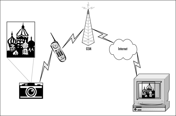
Bluetooth technology in our digital cameras and mobile phones will provide us with the ability to send the “instant postcard” shown in Figure 1.5. This could become almost as popular as Short Message Service (SMS) text messages. We take a picture with our camera, which instantly transmits the photo to our mobile phone that has a connection to the Internet via the Global System for Mobile Communication (GSM) network. From there, the picture is sent over the Internet to our friend’s PC. It’s a simple process which adds a new dimension to both products.
What if our gas and electricity meters could be read by the utility’s serviceman simply by walking into the foyer of an apartment block and connecting to each apartment’s meters individually to determine utility consumption? Not having to knock on each door would improve the efficiency of the job function but would inevitably mean that fewer personnel were required. With an application of this type, the cost implication and durability of Bluetooth technology comes to the fore. The ubiquitous gas and electricity meters have to last a long time, far longer than our favourite mobile phone or PDA which we change according to personal taste or consumer trends. The cost of replacing the meter infrastructure in our homes far exceeds the overhead of including Bluetooth technology, something which makes utility companies adverse to new technologies. Experiments have been conducted, but so far there has been no serious uptake.
With our children’s toys, the possibilities become endless. Big soft toys are able to communicate with PC games allowing for communication and interaction external to the PC. Multiplayer handsets for our Playstations become possible without a mass huddle around the console and the constraint of the cable length. Action figures and robotic toys could be remotely controlled from a PC, or could transmit pictures from a camera accessory to the PC.
Far more serious is the added functionality that can be provided for the disabled consumer, a headset could provide a life enhancing benefit to the physically compromised user—voice control for their heating, lights, AV, and security systems—allowing control from anywhere in their home. Wireless Internet access can also be of benefit. For instance, the National Star College in Cheltenham, UK has just installed a Red-M Bluetooth network to allow their disabled students to wirelessly access online resources and submit their course-work directly from their laptops. Discrete intelligent proximity sensors communicating with a headset could help the visually compromised, or a vibrating dongle could indicate to a deaf consumer that the doorbell is ringing or could be programmed to vibrate on other sound recognitions. All of these applications simply extend the functionality of conventional products by being Bluetooth-enabled.
Do You Have Time?
Okay, so we’ve decided we want to be wireless. We “must have” Bluetooth technology in our next product. The consumer market is not quite sure why they want it yet, but they do, so the first and most difficult hurdle is over with. But what do we need to do? And how long will it take? Both of these are serious questions. After all, implementing any new technology often incurs risks that may outweigh the advantages of the technology itself.
First of all, the Bluetooth Specification by the Special Interest Group (SIG) is an extremely comprehensive document, which needs to be digested before any form of implementation can begin. Both the hardware and software implementation are required in order to adhere to this specification and be able to utilize the intellectual property (IP) contained within it. It is essential to stick with the specification to be able to interoperate with any other Bluetooth device irrespective of manufacturer or solution provider; interoperability is the “key” to consumer uptake of Bluetooth technology and the realization of the Bluetooth Dream. Going up the Bluetooth learning curve can take significant time. Courses are available which make it easier, but you must still allow significant learning time in your development cycle.
If you are late in the product implementation cycle, you may not have time to build in Bluetooth technology. Or you may not have enough market information to reassure yourself that it will add sufficient value to justify the cost of shipping Bluetooth components in every product. Many early adopters initially added Bluetooth technology to existing products as “add-ons,” either as dongles or accessories to battery packs—mobile telephones being the principal example.
Using an “add-on” strategy allows you to decouple the Bluetooth development from your main product development. This means that you do not risk the Bluetooth development holding up your product launches. Since consumers can buy mobile phones, laptop computers and access points with Bluetooth technology fully integrated, this shows that the risks can be conquered successfully. Devices which implement Bluetooth technology as an “add-on” are likely to be less attractive to consumers when competing with built-in devices. So, when considering whether to build in or add on, you must survey the competition and decide whether your launch date means an “add-on” will not be as lucrative.
There is more to consider than the time to develop and manufacture your product. For any Bluetooth design to be able to display the Bluetooth logo, the design has to undergo a stringent qualification procedure and pass a vast array of tests on every aspect of the system from the radio, baseband, and software stack through to the supported profiles. This is achieved at a Bluetooth Qualification Test Facility (BQTF). Such test facilities can now be found globally, though they are becoming exceptionally busy and require booking many weeks in advance. In addition to the Bluetooth Qualification Program, product developers and manufacturers are required to meet all relevant national regulatory and radio emissions standards and requirements. This involves going through national type approval processes which vary from country to country. Qualification and type approval can significantly delay product launches, so they MUST be allowed for in your schedule.
Investigating Product Performance
In some of the applications previously mentioned, we can see that the many benefits of Bluetooth technology may outweigh the limitations, nevertheless we have only examined the subjective questions of added value and enhanced functionality. Now it’s time to consider in depth some of the technical limitations that may actually influence our choice of adding Bluetooth technology to our products, despite the much desired benefits.
In this section, we shall look at connection times, quality of service in connections, voice communications, and the various sources of interference.
Evaluating Connection Times
As we have mentioned, Bluetooth devices can’t connect instantly. It can take up to ten seconds to establish a Bluetooth link (although this is not a typical figure; tests with BlueCore chips show that 2.5 seconds is far more common). The connection time overhead is a limitation that could have serious consequences if you require an instant connection—a “panic button” would not be a viable application for Bluetooth technology. We will examine why and how this overhead can be reduced with a “known device” connection.
Wired networks are for the most part static. Components of the network are connected together with cables, and once connected, normally remain in the same position. A printer that was available on the network yesterday is expected to still be available tomorrow. However, you do have the initial overhead of configuring your PC to use it, the procedure being:
![]() Physically connect cables to new device.
Physically connect cables to new device.
![]() Type in address name on system that needs to use the new device.
Type in address name on system that needs to use the new device.
![]() Install drivers and configure software on system which needs to use new device.
Install drivers and configure software on system which needs to use new device.
Bluetooth piconets are highly dynamic—they change rapidly, with devices appearing and disappearing. The members of a piconet may change, or the whole piconet may be dissolved in a moment. In such a dynamic network, it is not viable to spend significant time acquiring information about devices and configuring software to use them: this process must be automatic. The Bluetooth core specification provides this automatic discovery and configuration. For a Bluetooth device, the steps to using a new device are:
![]() Perform device discovery to find devices in the area.
Perform device discovery to find devices in the area.
![]() Perform service discovery to get information on how to connect to services on each device discovered.
Perform service discovery to get information on how to connect to services on each device discovered.
![]() Choose a service to use, and use information obtained during service discovery to connect to it.
Choose a service to use, and use information obtained during service discovery to connect to it.
Potentially, the user could simply select the option to print, and the processes of device discovery, service discovery, and connection could happen automatically without further intervention from the user. The application software should present this to us transparently, but it is still a worthwhile exercise to understand the complete procedures; they are covered in the following sections.
Discovering Devices
Before any two devices can go through device discovery, they must be in inquiry and inquiry scan modes. The inquiring device must be trying to discover neighbouring devices, and the inquiry scanning device must be willing to be discovered (see Figure 1.6).
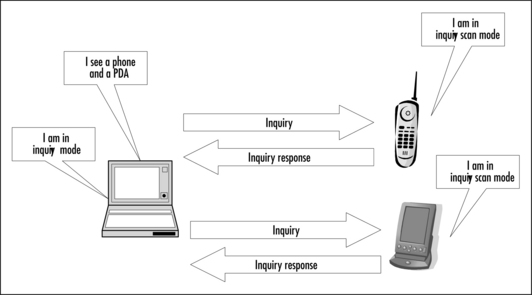
The inquiring device transmits a series of inquiry packets. These short packets are sent out rapidly in a sequence of different frequencies. The inquiring device changes frequencies 3200 times a second (twice the rate for a device in a normal connection). This fast frequency hopping allows the inquirer to cover a range of frequencies as rapidly as possible. These packets do not identify the inquiring device in any way; they are ID packets containing an inquiry access code which inquiry scanning devices will recognize.
The inquiry scanning device changes frequencies very slowly: just once every 1.28 seconds. Because the scanner changes very slowly while the inquirer changes rapidly, they will ultimately meet on the same frequency.
Scanning devices cannot stay on a fixed frequency, because any frequency chosen might be subject to interference, but hopping very slowly is the next best strategy for seeking the inquiring device. It responds to inquiries by sending a Frequency Hop Synchronisation (FHS) packet, which tells the inquiring device all the relevant information needed to be able to establish a connection.
To guarantee that the inquiring device can locate all the devices in inquiry scan mode that are within range, the Bluetooth Specification defines an inquiry time of 10.24 seconds.
When a device that is scanning for inquiries receives an inquiry, it waits for a short random period, then if it receives a second inquiry, it transmits a response back. It does not transmit this response immediately, because this may lead to all devices in a single area responding to the first inquiry sent out, causing an undesirable high-power coordinated pulse of radiation in the ISM band. The random delay prevents this coordinated effect.
Connecting Devices
Before two devices can establish a connection, they must be in page and page scan mode; the paging device initiates the connection, while the page scanning device responds. In order to be able to page, the paging device must know the ID of the page scanning device; it can calculate the ID from the page scanning device’s 48-bit Bluetooth device address. The page scanning device’s Bluetooth device address can be obtained in several ways:
Each Bluetooth device has its own unique 48 bit IEEE MAC Bluetooth address (BD_ADDR), which identifies it to other devices; if the device is a master, the connection timing and the hopping sequence are also derived from this address. Addresses are obtainable from the SIG in blocks and need to be programmed into every Bluetooth product at manufacture—all silicon is shipped with the same default address that must be changed. A “friendly name” may also be programmed into your product either by the user or at manufacture to enable the MMI to connect to “CSR development module,” “Daisy’s phone,” “Lara’s headset,” or “Amy’s little black book,” concealing the actual address. The address is concealed from the user because it is a string of numbers (typically expressed in hexadecimal) which is not a very user-friendly format. An example of a Bluetooth device address is 0x0002 5bff 1234.
By programming the device information that would normally be received in the FHS packet directly into the device, the inquiry and inquiry scanning can be avoided—devices move directly to paging, thus saving the 10.24 seconds required for inquiry. As previously noted, this could either be performed at manufacture, or carried out by the users. If we are manufacturing a mobile phone and a headset to be packaged together, the “out-of-the-box” experience will be one of disappointment if they do not communicate—they could be programmed such that they are both aware of each others’ BD_ADDR. This way they become “known devices” to each other and can avoid the inquiry stage—what’s called a preset link. We are also able to create a list of “known devices”—perhaps all the devices in our PAN.
Quantifying Connection Times
Now, we are aware of why connection times can be so long, but how long is long? What does this mean in minutes and seconds? The actual time is variable, depending upon the application software you are using, so you should look at what the Baseband Specifications specify. These, however, can be very confusing in giving definite minimum/maximum times used in inquiry and paging operations between devices, with the result that there may be a lot of speculation as to what these times actually are. Detailed in Table 1.2 are what the theory states should be the time taken to complete a typical successful Inquiry and Page operation, (that is, the typical time taken to set up an active Bluetooth link). To enable us to understand the basis of these figures, we will also briefly look at their origin.
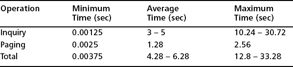
Inquiry Times An inquiry train must be repeated at least 256 times (2.56s duration), before the other train is used. Typically, in an error-free environment, three train switches must take place. This means that 10.24s could elapse unless the inquirer collects enough responses and determines to abort the procedure. However, during a 1.28s window, a slave on average responds four times, but on different frequencies and at different times.
Minimum Inquiry Time A minimum time for an inquiry operation is two slots (1.25ms). The master transmits an inquiry message at the f(k) frequency in the first instant, and the slave scans the inquiry at the f(k) frequency at the same time. So, the slave receives the inquiry message in the first slot. The slave could respond with a FHS packet to the master’s inquiry message in the next slot. So, in total two slots are needed. This is highly unlikely as the slave will not respond after receiving the first inquiry message but rather, wait a random number of slots. This random value varies between 0 and 1023.
Average Inquiry Time As stated previously, 10.24s could elapse unless the inquirer receives enough responses and decides to abort the procedure. This value can vary considerably, depending on alignment of the device clocks and their respective states. This, however, is not sufficient to guarantee all the devices within range will be “found”!
Maximum Inquiry Time 10.24s is what the user would typically expect for a maximum inquiry time—the amount of time specified until the inquiry is halted. 30.72 seconds has been suggested as a maximum time, although specifications state this can be up to a minute.
Paging Times Assuming you are employing the mandatory paging scheme (using page mode R1, where each train is repeated 128 times, before switching to the next one), then the average time for connection should be 1.28s. The maximum time for connection is 2.56s. During this, the A+ B train will have been repeated 128 times each, and a response returned.
Minimum Page Time This is similar to the Minimum Inquiry Time. When the master transmits a page message at the f(k) frequency in the first instant, the slave scans the inquiry at the f(k) frequency at the same time. Thus, the slave receives the page message in the first slot. The slave responds with an ID packet for the master’s page message in the next slot. Then in the third slot, the master transmits a FHS packet to the slave. Finally, in the next slot, the slave answers. Thus four slots (2.5ms) are needed for the minimum page duration.
Performing Service Discovery
When a Bluetooth-enabled device first enters an area there may be numerous other devices offering services it wishes to use. How does it tell which of these devices supports which service—in other words, which device will allow it to send an e-mail, print a fax, or exchange a business card? The Service Discovery Protocol (SDP) allows a device to retrieve information on services offered by a neighbouring device. (A service is any feature that another device can use.) A basic data connection must be set up before Service Discovery can be used. Then a special higher layer connection for use by Service Discovery is set up. Once the connection to service discovery is established, requests for information can be transmitted, and responses received back containing information on services. This information is known as the service’s attributes. If a device is finding out information about many other devices in an area, then it makes sense to disconnect after finding information on any particular device. This relieves system resources (memory, processor power), which can be more effectively used establishing new connections to other devices to determine what they have to offer. Because SDP uses ACL, connection devices must use inquiry and paging before they can exchange SDP information. As a result, SDP can be slow. SDP is mandatory for all the profiles released with version 1.1 of the Bluetooth specification.
Quality of Service in Connections
In Bluetooth technology, the ACL link supports data traffic. The ACL link is based on a polling mechanism between master and up to seven active slaves in a piconet. It can provide both symmetric and asymmetric bandwidth, which is determined by the ACL packet type and the frequency with which the device is polled.
The ACL payload is protected by a CRC check, which may be used in a retransmission scheme. The delay involved with retransmissions on the ACL link is small, as an acknowledgement can be received within 1.25ms. Further, the number of unsuccessful retransmissions can be limited by a Flush Timeout setting, which flushes the transmission buffer after a specified period of unsuccessful retransmissions. This opens the possibility to perform retransmissions for delay-sensitive applications such as interactive real-time and streaming (IP-based) audio/video applications. In most implementations currently available, the ACL link only provides a best-effort type of service (i.e., there are no Quality of Service (QoS) guarantees associated with the transfer of packets). It especially does not provide any guarantees of bandwidth and delay.
The Bluetooth specification does provide mechanisms to balance traffic between slaves in a piconet, allowing a so-called “guaranteed” Quality of Service. However, because the quality of the underlying radio link can never be guaranteed, in practice all that Bluetooth technology can do is to make an attempt to support the QoS it has guaranteed.
The unpredictability of radio interference means that if a guaranteed bandwidth is absolutely necessary for your product, then a wired link is really your best choice.
However, it is worth considering whether guaranteed bandwidth is really necessary. By compressing data and buffering it on reception, it is possible to overcome glitches in transmission. This can make a radio link appear far more reliable at the application level than it really is down at the baseband level!
Data Rate
If a Bluetooth device transmitted constantly on only one frequency, the maximum raw data rate would be 1 Mbps. However, this is not the data rate we will obtain over the air interface. Bandwidth is required for a 72-bit access code to identify the piconet, and a 54-bit packet header to identify the slave—total slot time: 405μs. The radio requires a guard band of 220μs between packets to allow it to retune and stabilize on the next hopping frequency. This guard band consumes the rest of the slot.
Within a one slot packet these requirements leave only one-third of the bandwidth for the payload data—and this can only be transmitted every other slot, or every 1250μs. One way to mitigate this limitation is to transmit for a longer period of time: 3 or 5 slots. All of the extra bandwidth is used for payload data with a consequent improvement in efficiency (illustrated in Figure 1.7). While transmitting over more than one slot, the devices remain at the same frequency, moving to the next frequency in the hopping sequence at the end of the packet. Thus, in a five slot packet, the master will transmit on f(k), and after the five slots will transmit on f(k+5). (A 16-bit CRC is also included in every ACL packet, but this is not illustrated in Figure 1.7.)
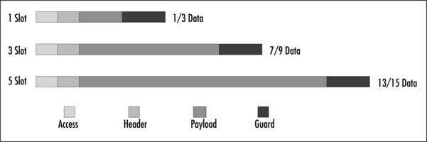
Bluetooth ACL packets can either be of Data Medium (DM) or Data High (DH) type. The DH packets achieve a higher data rate by using less error correction in the packet. A DH5 packet which utilizes five slots can carry the maximum amount of data: 339 bytes, or 2712 bits. So, if we take account of the packet overheads already discussed, 2858 bits are transmitted over the air interface for every 2712 bits of data payload. This gives us the maximum baseband data rate in a single direction of 723.2 Kbps – the single slot packets in this asymmetric link would carry 57.6 Kbps. If we chose to send five slot packets in both directions, the data rate would be reduced to 433.9 Kbps!
The choice of symmetric or asymmetric links allows our user scenarios to take account of the improvement in data rate in one direction of the asymmetric link (for example, our PDA browsing the Web via a server will require more bandwidth while downloading pages than it will require for us to specify the next link to browse.) Table 1.3 illustrates the maximum data rates with all of the packet types in both symmetric and asymmetric links.

Latency
Bluetooth technology achieves reliability by retransmitting packets. Each packet carries a header with an acknowledgement bit in it. When a device sends a packet, it uses the acknowledgement bit to signal whether the last packet it received was good or corrupted. When a device receives a packet with the acknowledgement bit set to indicate that its last packet was corrupted in transmission, it simply retransmits the corrupted packet. This retransmission carries on until it receives an acknowledgement that the packet got through correctly.
This can add delays (latency), and sometimes these delays can be variable (a bursty link). This may cause problems for applications needing a constant feed of data (e.g., compressed video). The effects of bursty links can be smoothed out by writing data into buffers as it is received, and reading it out a short time afterwards. As the on air link speeds up and slows down, the amount of data in the buffers gets greater or less, but as long as data is read out at the same average rate as it arrives, buffers can be used to smooth out a bursty link.
Some applications do not care if data comes in bursts, but they do need low latency (fresh) data. An example might be a monitoring application. If data has to be retransmitted, the monitor might freeze momentarily, but it is more important to get the most recent data than to have a smooth flow of packets. In this case, flushing can be used: at the transmitting end, data from the monitor could back up in the device’s buffers. A flush command tells a Bluetooth device to dump all stale data and start transmitting fresh data. It is possible to set up automatic flushing to avoid stale data accumulating.
Delivering Voice Communications
The voice quality on a Bluetooth SCO link is roughly what you’d get from a cell phone—in other words, it’s not hi-fi quality.
The audio data is carried on SCO channels, and to establish a SCO channel, you must first set up an ACL (data) channel. This is because the ACL channel is used by the Link Manager to send control messages to set up and manage the SCO channel.
SCO channels use prereserved slots; reservation of slots ensures the integrity of the SCO packet. There are three different types of SCO packets, each of which requires a different pattern of reserved slots.
![]() An HV3 packet carries 30 bytes of encoded speech with no error correction. A SCO link using HV3 packets reserves every third pair of time slots available to a device.
An HV3 packet carries 30 bytes of encoded speech with no error correction. A SCO link using HV3 packets reserves every third pair of time slots available to a device.
![]() An HV2 packet carries 20 bytes of encoded speech plus 2/3 Forward Error Correction (for every 2 bits of data, 1 bit of error correction is added to give a total of 3 bits). A SCO link using HV2 packets reserves every second pair of time slots available to a device.
An HV2 packet carries 20 bytes of encoded speech plus 2/3 Forward Error Correction (for every 2 bits of data, 1 bit of error correction is added to give a total of 3 bits). A SCO link using HV2 packets reserves every second pair of time slots available to a device.
![]() An HV1 packet carries just 10 bytes of encoded speech protected with 1/3 Forward Error correction (for every bit of data, 2 bits of error correction is added to give a total of 3 bits). A SCO link using HV1 packets reserves every pair of time slots available to a device.
An HV1 packet carries just 10 bytes of encoded speech protected with 1/3 Forward Error correction (for every bit of data, 2 bits of error correction is added to give a total of 3 bits). A SCO link using HV1 packets reserves every pair of time slots available to a device.
Because the SCO links reserve slot pairs for voice packets, they prevent the use of 3 or 5 slot packets for data transmission. The multislot packets can support higher data rates than single slot packets, this combines with the slots used by the voice link to reduce the maximum data throughput if SCO and ACL transmission occur concurrently.
The Bluetooth specification supports several coding schemes: Log PCM A-law, Log PCM μ-Law, and CVSD. Log PCM coding with either A-law or μ-law compression was adopted by the Bluetooth specification because it is popular in cellular phone systems. Continuous Variable Slope Delta (CVSD) modulation is supported in the Bluetooth specification because it can offer better voice quality in noisy environments. The Bluetooth audio quality is approximately the same as a GSM mobile phone—this translates to audio transmitted at a fixed data rate of 64 Kbps.
A master is capable of supporting up to three duplex audio channels simultaneously. These channels could be either to the same slave or to different slaves. Because voice transmissions are inherently time-dependant, SCO packets are never retransmitted, so any packets that are not received correctly are lost. In noisy environments, the errors introduced by lack of retransmission capabilities can have a serious impact on the quality or intelligibility of the received audio.
Bluetooth technology does not have the bandwidth for raw CD quality sound: 1411.2 Kbps. However, if a suitable compression technique is employed (for example, MP3 compressing an audio stream to 128 Kbps), it is feasible to use an ACL link for high-quality audio. An audio-visual workgroup is currently working within the Bluetooth SIG to provide a profile which will improve the maximum audio quality that can be delivered across Bluetooth links. As compressed audio incurs a delay in transmission, the existing SCO scheme will be retained for applications (such as cell phone headsets) where the bandwidth of the audio signal is already low.
Investigating Interference
The Bluetooth system operates in the 2.4GHz band. This band is known as the Industrial Scientific and Medical (ISM) band. In the majority of countries around the world, this band is available from 2.40–2.4835GHz and thus allows the Bluetooth system to be global. It is available for free unlicensed use in most of the world, although some countries have restrictions on which parts of the band may be used. However this freedom has a price—many other technologies also reside in the band:
![]() Some Digital Enhanced Cordless Communications (DECT) variants
Some Digital Enhanced Cordless Communications (DECT) variants
![]() Some handheld short-range two-way radio sets (walkie-talkies)
Some handheld short-range two-way radio sets (walkie-talkies)
These are all intentional emitters—one way or another their function is to generate microwave radiation in the ISM band. In addition to the intentional emitters, Bluetooth technology is subject to interference from a variety of sources which emit accidentally:
There are also problems from signal fading due to distance or blockers such as walls, furniture, and human bodies. The more water content in the object, the more significant the effect of blocking. Old brick walls will have a higher water concentration than modern ones due to the nature of their constitution. This tends to cause fading in European houses where brick is a common construction material. In the USA, where timber frames are more popular, signals are much less affected by internal walls.
As with any radio technology, Bluetooth technology is prone to interference from its co-residents in the ISM band and will produce interference to them. To achieve a degree of robustness to interference, the Bluetooth system utilizes a frequency-hopping scheme: Frequency Hopping Spread Spectrum (FHSS). Constantly hopping around the different radio channels ensures that packets affected by interference can be retransmitted on a different frequency, which will hopefully be interference free. Bluetooth radios hop in pseudo random sequences around all the available channels. During a connection, they hop every 625 microseconds. When establishing a connection, they can hop every 312.5 microseconds.
The screenshot in Figure 1.8 is taken from a Sony/Tektronix WCA380 spectrum analyser and illustrates 30MHz of spectrum in the centre of the ISM band. The upper section shows a snapshot of output power against frequency at a single instant in time. The lower section shows time against frequency with the power level displayed by way of shading.
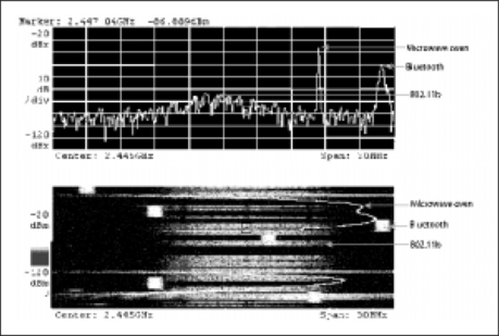
The screenshot clearly illustrates the spectral characteristics of microwave ovens with a strong but narrow spike of power, on the lower section of the screenshot. This wanders around the center of the ISM band as the oven operates, showing on the analyser screen as a curving red line. Our Bluetooth FHSS system can be seen to be hopping with 1MHz channel spacing with a strong central peak. The IEEE 802.11b or Wi-Fi DSSS system can be seen to have lower output power, indicated by the broad seep of power in the center, but the signal can spread across about 16MHz. (This is why co-located Wi-Fi networks cannot use adjacent channels.)
A Bluetooth FHSS system operating near an interfering signal can cope if a packet is hit by interference. The affected device simply retransmits the packet contents in the next slot when it has moved to a different frequency which is no longer affected by interference. This will impact on the throughput of an ACL link—the more interference, the more retransmissions. With a SCO link, it’s a different matter. SCO data is not reliable, due to its inherent nature of being in real time, and retransmission is not tangible, so audio clarity becomes significantly worse with any interference. This can be overcome by sending SCO data via an ACL link.
Transfer of ACL information will still be reliable in a noisy environment. No information is lost as each dropped packet is retransmitted. The impact manifests itself in the data rate: the more noisy the environment, the more retransmissions will be required.
Figure 1.9 illustrates the effect of Bluetooth technology throughput in the presence of Wi-Fi interference. We can see that our Bluetooth device’s throughput is degraded when a Wi-Fi device is very near. However, when the Wi-Fi device is relocated ten meters away, the throughput significantly improves. It is actually approximately 90 percent of the baseline throughput independent of range, thus illustrating that when Bluetooth and Wi-Fi devices are at a reasonable distance, the degradation in performance is tolerable.
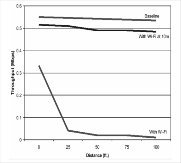
Figure 1.9 The Effect of Bluetooth Throughput with Wi-Fi Interference (Courtesy of Texas Instruments)
Interfering with Other Technologies
Figure 1.10 illustrates the degradation our Bluetooth devices can have on Wi-Fi when they are extremely close to a Wi-Fi station. The impact on performance due to interference is significant. However, when our Bluetooth devices are relocated as little as ten meters away, the throughput is only minimally reduced compared to the baseline.

Figure 1.10 The Effect of Wi-Fi Throughput with Bluetooth Interference (Courtesy of Texas Instruments)
The last two figures indicate that the two wireless technologies can easily coexist as long as we are sensible in our expectations and attempt to combine the technologies in our PAN and HAN paradigms intelligently. One way is to not have a Wi-Fi access point, providing us with the high data rate required for video streaming too close to the desk where our PDA and laptop “do their thing”!
Coexisting Piconets
A consideration not yet discussed is Bluetooth devices interfering with Bluetooth devices. How many devices do we need to reduce the data throughput to a trickle?
Consider the scenario of having Bluetooth devices in every room, With PANs for each member of the household. The majority of teenagers today have a PC and a mobile phone at the very least. Combine this with the toys of our younger children (and ourselves!) and any “household” Bluetooth devices; access points, control units, security systems, and so on. This adds up to tens of devices operating in the same area. Admittedly, they will not all be operational at the same time, so significant degradation is not likely to occur, But if our product requires dependable data delivery, the retransmission overhead that interference can cause might make Bluetooth technology unviable. Figure 1.11 illustrates how the probability of a packet collision increases with the number of operating piconets.

Using Power Control
We must also consider the respective power class of our Bluetooth devices. To enable all classes of device to communicate in a piconet without damage to the RF front ends of the lower power devices, a method of controlling the output power of Class 1 (100mW) devices is required.
Transmit power control is mandatory for Bluetooth devices using power levels at or above 4 dBm. Below this level (i.e., all Class 2 and 3 modules), it is optional. To implement a power control link, the remote device must also implement a Receive Signal Strength Indicator (RSSI). A transceiver that wishes to take part in a power-controlled link must be able to measure its own receiver signal strength and determine if the transmitter on the other side of the link should increase or decrease its output power level.
To set up a power controlled link, the transmit side must support Transmit Power Control and the receive side must support RSSI. Support is indicated in the Locally Supported Features (Bluetooth Spec 1.1 Part C (LMP) Section 3.11). The RSSI need only be able to compare the incoming signal strength to two levels: the Upper and Lower Limits of the Golden Receiver Range. The Lower Limit is between −56 dBm and is 6 dB above the receive sensitivity (0.1 percent BER level) for the particular implementation. The Upper Limit is 20 dB +/− 6 dB above this. The RSSI level is monitored by the receive side’s Link Controller. When it strays outside the Golden Receiver range, the Link Manager is notified. A message is sent to the transmit side, requesting an increase or decrease in transmit power to bring the RSSI back in line. If the transmitter is a master, it must maintain separate transmit powers for each slave.
Host Controller Interface (HCI) commands exist to find out the current transmit power and RSSI level, but they are for information only. Layers above the Link Manager are not directly involved in power control. The implication of this is that it is perfectly possible to sit a Class 1 module transmitting at +20 dBm right next to another module which does not support RSSI and not limit the first’s transmit power. If the second module’s maximum receivable level is the Bluetooth spec of −20 dBm, there is every chance its RF front end will be overloaded. RSSI, although not mandatory, is highly recommended, as is a large power control range implemented on all modules, not just Class 1.
Figure 1.12 illustrates interfering Bluetooth piconets, but the principle holds true for coexisting networks of different technologies. Devices that are close to one another turn their power down and do not interfere with devices at a distance. Devices transmitting a long distance have to turn their power up to reach one another, which generates more interference and affects more devices. The hypothesis for us is ultimately to persuade our consumers to site devices intelligently. The home user is typically unaware of the implications of radio interference and will not position their devices for best performance!

Aircraft Safety
The Federal Aviation Authority (FAA) does not permit “intentional emitters” to be active on planes in flight. Bluetooth technology is an intentional emitter and as such is not legally usable on flights covered by FAA regulations. This means that any systems such as Bluetooth radio tags, which automatically identify baggage for airline baggage handling systems, need to be deactivated in-flight. The inconvenience of deactivating devices may mean that passive radio tags would better suit some applications. Certainly, in-flight deactivation issues must be considered by anybody whose products may be used in an aircraft in flight.
Assessing Required Features
The Bluetooth specification has many optional features, and even if features are mandatory to support, they do not have to be enabled. This section briefly examines a few features of the Bluetooth specification that may affect your product.
Enabling Security
To prevent unwanted devices connecting to our personal devices, or to prevent our personal data from being “snatched” from the air, Bluetooth technology provides security in the form of a process called pairing. It utilizes the SAFER+encryption engine, using up to 128-bit keys. How this provides us with the means to “pair” with another selected device and create a secure link is interesting.
It is possible to “authenticate” a device—this allows a pair of devices to verify that they share a secret key. This secret key is derived from a Bluetooth pass key or Personal Identification Number (PIN). The PIN is either entered by the user or, for devices with no MMI (such as a headset), it will be programmed in at manufacture. After the devices have authenticated, they are able to create shared link keys which are used to encrypt traffic on a link. This combination of authentication and link key creation is called pairing.
Pairing devices allows communication secure from eavesdropping, but enabling security can make it much more difficult to connect with other people’s devices, thus security features can seriously compromise usability. For devices where disabling security may be appropriate, the user interface should allow security to be turned on and off simply.
Using Low Power Modes
The Bluetooth specification provides low power modes, hold, sniff, and park. Devices in low power modes can still be connected to another device, remaining synchronized to that specific hopping sequence and timing, even though they do not have to be active. Thus, when they wish to communicate, they do not have to perform the inquiry, page, SDP procedure again—they are effectively just “reactivated.”
Hold Mode
The ACL link of a connection between two Bluetooth devices can be placed in hold mode for a specified hold time. During this time no ACL packets will be transmitted from the master.
Hold mode is typically entered when there is no need to send data for a relatively long time—for example, if the master is establishing a link with a new device. During hold mode, the Bluetooth transceiver can be turned off in order to save power.
What a device actually does during the hold time is not controlled by the hold message, but it is up to each device to decide. The master can force hold mode if there has previously been a request for hold mode that has been accepted. The device in hold mode always retains its active member address (AM_ADDR). After the hold period has expired, the slave resynchronizes to the master and the active connection resumes.
This allows for our laptop to place our PDA that it is connected to in hold mode while it establishes a connection to a LAN access point, thus minimizing PDA power consumption when not in use.
Sniff Mode
In sniff mode, the slave remains synchronized to the master, but the duty cycle of the slave’s listen activity can be reduced, thus placing the constraint upon the master to only transmit in certain slots. To enter sniff mode, master and slave devices negotiate a sniff interval and a sniff offset, which specifies the timing of the sniff slots and the occurrence of the first sniff slot. After this negotiation, the sniff slots follow periodically according to the prenegotiated sniff interval. In order to avoid problems with a clock wrap-around during the initialization, one out of two options is chosen for the calculation of the first sniff slot. A timing control flag in the message from the master indicates this. In sniff mode, the slave retains its AM_ADDR. This mode is extremely useful if we have our PDA waiting to receive e-mail from our phone. Normally, there will not be any traffic, but the PDA needs to be ready quickly when there is.
Park Mode
If a slave does not need to participate in the channel (that is, it is no longer actively transmitting or receiving data, but needs to remain in the piconet and thus remain synchronized to the master), it must monitor the master’s transmissions periodically so that it can keep synchronized. Park mode allows this by having the master guarantee to periodically transmit in a beacon slot. Because the parked slave can predict when a beacon transmission will happen, it can sleep until the master’s beacon is due.
In park mode, the device relinquishes its AM_ADDR. Instead, when a slave is placed in park mode it is assigned a unique park-mode-address (PM_ADDR), which can be used by the master to unpark slaves.
Parked slaves must still resynchronize to the channel by waking up at the beacon instants separated by the beacon interval. A beacon offset and a flag are sent in the park message to indicate the instant when the beacon will first happen. A beacon interval is also sent in the park message. Beacons happen periodically separated by the beacon interval.
Park mode conserves the most power and would be appropriate for a device in our PAN that we would only want to randomly access—for example, the printer, which we could un-park when we required its services but not go through the lengthy inquiry procedure each time.
The headset profile allows park mode to be used with headsets, this is so that when an incoming call is received, a cellular phone can rapidly unpark the headset instead of having to wait for a lengthy connection procedure to finish.
Unparking
Via the beacon instant, the master can activate the parked slave, change the park mode parameters, transmit broadcast information, or allow the parked slave’s request access to the channel. All messages sent from the master to the parked slaves are broadcasted, and to increase reliability for broadcast, the packets are made as short as possible.
Following the beacon slots, there are a number of access windows defined, through which parked slaves can request to be unparked. The access window that they request to be unparked in is determined by the PM_ADDR assigned to them by the master when they are parked. This allows the parked population to share the access windows, thus reducing the probability of a collision if two slaves require unparking at the same time. Slaves have to be unparked periodically by the master in order to ensure that they are present and that any virtual connections can be maintained.
Which Devices Need Low Power Modes?
In practice, most devices will need to support low power modes. Consider the case of a desktop PC. It is connected to mains power, so it has no need to save power. However, it could communicate with a battery-powered Bluetooth mouse, which will want to use sniff mode to extend its battery life. If the PC does not support sniff mode, the mouse cannot use it, and so its battery life can be seriously compromised by lack of features in the PC.
Similarly the PC may connect with a PDA which wants to synchronize and would like to be put in hold mode if the PC needs to interrupt the synchronizing process to go and service another device.
Park mode might be needed if the PC is connected to a cellular phone so that the PC’s microphone and speakers can be used as a hands-free set for the phone.
Do not just consider the requirements of your product—think about the impact your product’s capabilities could have on other devices used with it.
Providing Channel Quality Driven Data Rate
The Bluetooth specification provides a variety of packet types—single and multiple slot packets, each coming in medium- and high-rate types.
Multislot packets pack more data into longer packets, and provide higher throughput in noise-free environments, but their throughput is worse than single slot packets in noisy environments because they take longer to retransmit.
Medium rate packets have more error protection. This makes them tolerant to noise, but the space taken up by error protection means they cram less data into each packet. High-rate packets get better throughput in error-free environments, while medium-rate packets get better throughput in noisy environments.
Channel quality driven data rate (CQDDR) allows the lower layers of the Bluetooth protocol stack to measure the quality of the Bluetooth channel, and choose the packets most appropriate to the noise levels. Not all chips/chip sets implement CQDDR, so if you expect maximum throughput in noisy conditions to be an important factor for your product, you should ensure that you choose a chip/chip set which implements this feature.
Deciding How to Implement
Once you have made the decision to implement, what are the available options for Bluetooth technology enabling your products?
There are many options to consider in both hardware and software. Even once you have chosen a chip set and protocol stack, there are different ways that these can be added into your product. In this section, we shall begin by looking at software system architecture, then we’ll consider some of the hardware options.
Choosing a System Software Architecture
The choice of system architecture will obviously be determined by footprint, cost, and time-to-market, but the end functionality will have the biggest influence. We will briefly examine the Bluetooth protocol stack as it can have an influence on our product’s system architecture.
We will examine the stack in its simplest form—the upper stack and the lower stack. The lower stack controls all of the physical functionality, the radio, the baseband, and the Link Manager (LM) and Link Controller (LC) layers.
The upper stack deals with the channel multiplexing, with the logical link control and adaptation protocol (L2CAP). Serial port emulation and the interface with the application software happens in the RFCOMM layer. A Service Discovery Protocol (SDP) layer is also essential for all Bluetooth devices, as it allows them to find out about one another’s capabilities—an essential facility when you are forming ad-hoc connections with devices you may never have seen before.
There are three implementation models for the stack, dependant upon the functionality or resources the respective product has: hosted, embedded, and fully embedded (see Figure 1.13).
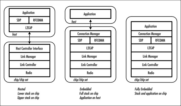
In the hosted model, the lower stack layers reside on the Bluetooth (BT) device, while the upper stack resides on a host (this may be a PC or a micro-controller if the product is mobile or standalone). They communicate via the Host Controller Interface, which sits between the lower layers and upper layers of the protocol stack forming a bridge between them. The two most common physical transports are UART (H4) and USB (H2). The UART protocol was designed for communication between chips on the same board and does not cope well with errors that occur in cables, so there are also proprietary transports which add extra facilities to the simple UART protocol. One example is CSR’s BlueCore Serial Protocol (BCSP) which achieves a more reliable form of UART transport with retransmission and error checking. The hosted model is optimum for applications where powerful host processors are already available and there is plenty of memory. Examples of hosted devices include USB dongles, PCMCIA cards, compact flash cards, V90 modems, Internet gateways, and PC motherboards.
In the embedded model, the complete stack resides on a BT device, but a separate user application is running on a host. This model is ideal for 2 and 3G mobile phones, ticket or vending machines, or PC peripherals that have limited processing power and available memory.
In the fully embedded model, the complete stack and the user application are all on the Bluetooth device. There is limited memory resource on the BT device so any application will need to be relatively simple. The best example of a fully embedded device is a headset. It has no need for complex processing, so the whole Bluetooth stack can run on the single microprocessor within the BT chip/chip set.
The lower stack up to the HCI is always provided with the Bluetooth chip/chip set as it is unique to that silicon implementation. With the embedded model, the upper layers are also provided by the chip/chip set vendor—either free of charge if it is their own stack or there may be a license fee per device if they are using another vendor’s upper layers. The fully embedded model requires a silicon solution that allows the application code to be written and downloaded to it without compromising the integrity of the Bluetooth stack which should have already undergone the stringent qualification procedure. Any changes to the stack requires it to be requalified!
The upper stack layers, above HCI, can be licensed from numerous vendors. Due to the inherent interoperability requirement of any qualified Bluetooth component, the choice is open. All of the available stack offerings “will” be compatible with the chosen silicon’s lower layers. You can, of course, write your own upper layers, but it will be a vast software undertaking—illustrated by the cost of licensing one. Protocol stacks can be expensive, but an expensive stack might just offer you extra features which help to sell your product. Because of this, examine all the available options closely.
As the Specification stabilizes, there will be chips entering the market dedicated to a specific purpose only—the headset profile being the primary example. The chips will have all the relevant stack layers and the profile implementation in masked ROM, reducing the cost significantly.
Constraining Implementation Options with Profiles
The Bluetooth profiles deliberately restrict implementation choices. If you are implementing functionality, which is covered by a profile, then you must implement that profile. This is intended to make it easier for devices to interoperate: if everybody implemented their own proprietary methods of communicating, then nobody’s devices would ever work together.
You may find that you do not want to follow the profiles, many of them are compromises intended to provide functionality that will address a variety of potential use cases. This means that they may not be optimum for what your application and your product wants to do. This need not be a problem: once you have implemented the relevant Bluetooth profile, you are free to also implement your own proprietary solution.
You may find that having to implement profiles makes Bluetooth technology too burdensome, and this might start to make alternative technologies such as infra-red look attractive. However, you should consider that by implementing a profile, you have vastly increased the number of devices which will interoperate with your product.
Choosing a Hardware Implementation Option
Choosing a software architecture may limit the choice of hardware. Some chips/chip sets can not support the complete protocol stack, so if you do not have a hosted system, you will have ruled out these options. Still, there is likely to be a range of chips/chip sets open to you, each with its own inherent compromises, in time-to-market, cost, and R&D resource.
There are numerous solutions currently available from multiple vendors. Chip sets come as separate radio and baseband devices in a variety of technologies: silicon-germanium, silicon-on-insulator, and CMOS, or as single-chip CMOS device integrating the radio with the baseband. Chip set prices range from $8 to $29, although this will no doubt decrease with large volumes. This option is designed-in directly onto the product’s printed circuit board (PCB).
The alternative to buying a chip set is to get a “module.” These are PCBs complete with RF deign and antenna, and will be pre-tested and pre-qualified.
All qualified Bluetooth components and products are listed on the “qualified products” section at www.Bluetooth.com (the official SIG Web site). Here you will find the manufacturers of chips/chip sets, modules, development kits, and software components. Data sheets or specifications can then be attained from the respective manufacturer’s own Web site, as well as information on how to purchase.
The single chip/chip set approach requires an RF design resource to provide the matching networks, filters, amplifiers, and antennas to the transmitter and receiver paths and will require expensive synthesis and test equipment along with a lengthy qualification process. It will, however, incur a significantly lower financial cost per unit along with a reduced PCB real estate overhead. Many chip/chip set manufacturers will supply you with reference designs. If you exactly follow their instructions, you can get away without designing your own system. You must be very careful if you are following a reference design; apparently insignificant changes can alter the radio performance. For instance, changing the manufacturer of a capacitor can change its characteristics even though it might be listed as the same value and type.
The module approach is far simpler since the primary RF hardware concern is soldering the module onto your motherboard. Keep in mind that it’s larger to integrate onto your motherboard and financially more expensive. Figure 1.14 provides examples of some of the available options and their dimensions. The multiple chip approach separates baseband and radio into two packages, whereas single chip combines both. The single chip approach can also be divided into single chip plus flash (allowing larger flash memory), or single chip with integrated flash (for minimum size).

Whichever stack configuration you choose, you will still have to somehow add the hardware. There are two primary options for adding the Bluetooth hardware to a product: designing Bluetooth technology directly onto the PCB, or using a pre-qualified complete Bluetooth module. In the following sections, we will briefly question how each method will impact on time-to-market and what the more common risks of implementation are likely to be.
This is by no means a definitive summary. Every individual application will have its own unique implementation issues. You can, of course, employ a third party design house to do it for you and let their designers go through the learning process! The most expensive, yes, but if you have no R&D resource yourself, this may be your only route to joining in the Bluetooth Dream, and it is certainly easier than trying to recruit and manage a complete development team if you don’t have one already. There are many design houses that now specialize in Bluetooth design, thus you would get the additional benefit of their experience.
Design Bluetooth Directly Onto the PCB
Designing Bluetooth technology directly onto the PCB is the optimum method if PCB real estate or end unit costs are our primary design constraints. Choose the silicon wisely. Devices are available that have a comprehensive level of integration and do not require difficult-to-source/expensive external components—SAW filters being the obvious example. If we are using a “hosted” stack configuration, we need to ensure that the HCI transport is available and fully functional. As the Bluetooth system has many optional features, we also need to check that our chosen silicon vendors lower stack implementation provides the Bluetooth functionality that we require. PCB real estate needs to be available and thus will affect our choice of solution. A PCMCIA card or PC motherboard, for instance, is a predefined size, irrespective of component population. As a result, the smallest solution is not a primary objective; however for a headset, a compact flash card or a mobile phone size would be a significant determining factor.
PCB structure is an issue if we use this method. Due to the inherent nature of RF striplines and microstrip, a multilayer PCB is needed to give the required power planes, ground planes, and associated dielectrics, and to separate the digital signals to avoid noise pickup in the RF and crystal sections. The PCB is a high proportion of the manufacture cost, if the product typically uses a two layer PCB. This additional cost overhead can impact significantly on the total unit budget. For large PCBs, the cost of a multilayer board may swing the balance in favor of a separate Bluetooth module, allowing the multilayer section to be kept as small as possible. Figure 1.15 is an example of the PCB structure required for a Class1 Bluetooth design.

The fastest time-to-market approach if we use this method is for us to use one of the chosen silicon vendor’s reference designs. These are normally free-of-charge on purchase of a Development Kit, and will have been proven and qualified. Most vendors provide a schematic and a set of Gerber files that can be imported into our own computer aided design (CAD) packages ensuring exact translation of the crucial PCB tracking layout. Some of us may know better, however, or have our own ideas (for instance, if a lumped balun is recommended in the reference design but you wish to use a printed one as a cost-saving exercise). Experience has illustrated that this can work but may incur repeatability problems with secondary PCB batches. You may wish to use a different power amplifier (PA) for a Class 1 design to the one recommended. Again, cost or a favorite supplier may be an influencing factor. Check with the silicon vendor. They would have evaluated several prior to selecting the one in the reference design. Most chip/chip set vendors work closely with the other Bluetooth component manufactures to provide us with a wide choice of options not all at a cost premium! To get Bluetooth technology into as many consumer products as possible, the ultimate aim is to get the Bill Of Material (BOM) cost on a downward spiral to the now infamous $5 target, which was set during the press hype of the initial technology rollout. This sum represents the cost to replace the average data cable! Figure 1.16 illustrates this method, showing the Bluetooth device and the flash memory (the two chips towards the bottom of the card).

The most common risks associated with this approach can be very simple but add serious time delays to project schedules. A simple component change to improve a matching network between the Bluetooth device’s transmitter output and a PA, for example, can incur problems with your manufacturer’s component stock and tooling, and cause havoc with any quality assurance (QA) procedures that have been developed concurrently with the design to meet a project production deadline. Examples of the two problems that could have a significant impact on time-to-market are detailed next (design verification and manufacturing). However, test equipment incompatibility, qualification testing, and ultimately, production test development will also have their own impact.
Programming and Upgrading Firmware
How we get the firmware into our chip/chip sets could become a design nightmare considering that the Bluetooth specification is still undergoing revision, and the silicon vendors are still developing their lower stack firmware either for the purpose of adding new functionality or remedying interoperability “bugs.” We must have a means to upgrade the firmware in our development labs, our manufacturing sites, or in the “field,” if we have put our products onto the market.
All of the silicon available today uses flash technology as the storage media. This enables programmability for upgrades. The ideal scenario would be to program the flash initially via a programming/debug interface. This would require the respective interface pins from the chip to be brought out to pads on the PCB. In a development environment, we could then attach a cable; while in a production environment, we could use a “bed-of-nails” approach.
But what about the “field” products? Do they join the ever increasing pile of technical obsolescence, or do we recall them? Do we really want to put ten thousand or more products straight off the production line back through the same production line for reprogramming? The solution is to follow the example of those clever USB chaps: Device Firmware Upgrade (DFU). A DFU facility allows us to upgrade our products over the standard UART or USB interfaces via software, and requires no soldering of cables or secondary production runs. A “bootloader” is programmed into the chip when it is initially programmed via the methods previously mentioned. The bootloader can be used with upgrade software shipped with our products to provide the “in-the-field” upgrade facility to our customers.
As lower stacks mature and the specification stabilizes, this will not be such a pertinent issue. Nevertheless, before selecting a silicon solution check the programming and upgrade facilities that it offers you, and when designing your systems, consider how you might take care of upgrades both on the production line and in the field.
Design Verification
Design verification can be a problem: despite the most precise synthesis, the prototype may not always exhibit the same RF characteristics in reality. This can involve lengthy diagnosis, component changes, or a board respin if layout issues are suspected to be the cause of the problem.
This can be overcome by the development of several prototypes concurrently, as well as adhering to the selected silicon vendors’ design guidelines. If advice states that the device is sensitive to noise, you will know not to run digital lines from the flash next to the Bluetooth device or under the system crystal, and to take de-coupling very seriously! Figure 1.17 illustrates the problems caused if a design routes the address and data bus (or another digital line that changes rapidly) near the crystal or its traces. Any digital signal has fast edges which can easily couple several millivolts into a small signal output from a crystal; this is not helped by the lack of drive you receive from a crystal. As the crystal output passes through the Phase locked loop (PLL) comparator, a slice level is used to determine if the crystal output has changed from a zero to a one, or vice-versa. If there are glitches on the crystal output from digital coupling that are greater than the hysteresis of the comparator, it can result in the square wave output having glitches or excessive jitter. Glitches can confuse the divider and phase comparator and result in excessive frequency deviation at the output, which will cause variations in the RF output.

Figure 1.18 illustrates the noise incurred on the output spectrum due to insufficient filtering of the power supply to the BT device, the top trace. This will have a detrimental effect on system performance and will impact negatively on some of the qualification tests for frequency drift and drift rate.

Manufacturing
As previously indicated, the manufacture of Bluetooth PCBs themselves can be problematic. Repeatability of performance with printed RF components and the expense of the multilayer PCB, as well as other problems can be incurred with component placement. As this method of design is optimum for size, the physical dimensions we are working with can be extremely small. This means we have to be precise not only in our layout for noise, feedback, and coupling issues, but also with pad size and component placement.
The Bluetooth chips/chip sets available are mainly packaged as ball grid arrays (BGAs), and the associated passive components have to be the surface mount 0402 type to adhere to the size constraint. There are many factors to take into account when using components on this scale: unless the solder resist finish is of the photo image type with a maximum thickness of 0.025mm, the 0402 resistors and capacitors could be lifted away from the pads on the PCB. A maximum solder resist window around the component pad should be in the region of 0.05mm with an alignment tolerance of 0.05mm to ensure that any tracks or vias between the pads of the BGA are not exposed, reducing the risk of short circuits. Figure 1.19 illustrates some of the problems expected if we get this wrong!
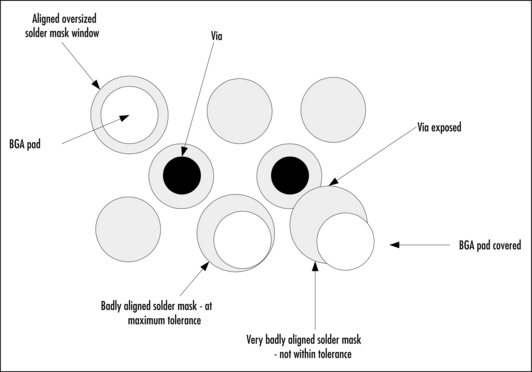
Using a Prequalified Complete Bluetooth Module
Using a prequalified complete Bluetooth module is optimum if time-to-market is our primary design constraint. We have the PCB real estate available and can transfer the additional cost per unit to our end users while remaining competitive.
Modules are available from numerous sources with a choice of Bluetooth silicon. They are available in class 1 or class 2 and can take several forms. Modules are currently being developed that integrate the entire external RF and system components (flash, crystal, filters, and amplifiers) into a single device—predicted sizes being as small as 5mm by 5mm! These modules are all pretested and pre-qualified, thus simplifying both the production test and qualification required for our end product. Examples of two modules currently available are illustrated in Figures 1.20 and 1.21.
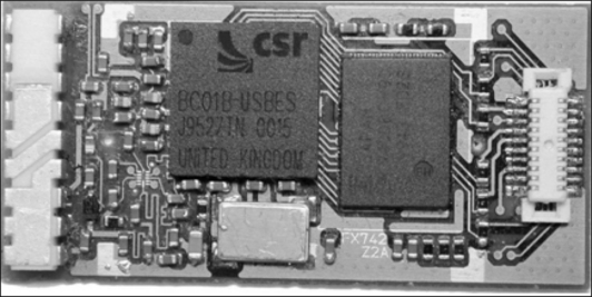
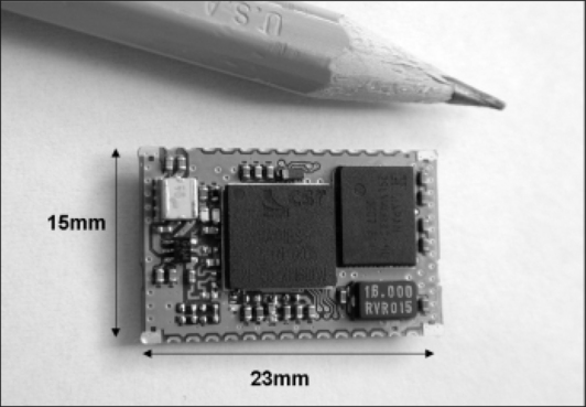
The PCB issues examined in the previous method are irrelevant when using a module since we just solder the module onto our own PCB. There are no new Bluetooth technology-induced RF layout considerations or BGA placement issues. Of course, we must ensure that the antenna is placed in a position where propagation is not adversely affected by surrounding components, and this will require some RF expertise. But antenna siting is really the only RF issue we have to think about.
This method, however, would not suit size-conscious products. The added module will currently increase the overall height of the PCB, which isn’t appropriate if your product has to fit in a PC slot where dimensions are predefined and resolute. There are limitations to this method other than cost, size, and supply, although how seriously they affect us will be subjective and dependent upon our own requirements.
Firmware Versions
The module will be supplied with a version firmware deemed appropriate at manufacture. However, the respective silicon on the module may have undergone many revisions since the module was produced. We are dependant on the module manufacturer to provide us with access to this new firmware and provide us with the means to upgrade it.
Dependant for Functionality
The module we have chosen will be static. It will only provide us with the ability to configure our product designs according to its specification. If we require, for instance, to change the PCM interface to utilize a more price-conscious or better performing codec, we will require access to the Bluetooth chip/chip set that the module is based upon to reconfigure it. If this could affect your product, then ensure that this reconfigure option is available from the module you choose.
Obtaining Bluetooth Technology Qualification
In order to obtain qualification of a component or product, the manufacturer may use a test house for two services:
![]() The test house is contracted to make tests to a Bluetooth test specification, and to produce a test report containing the results of the tests.
The test house is contracted to make tests to a Bluetooth test specification, and to produce a test report containing the results of the tests.
![]() An employee of the test house who is appointed by the Bluetooth SIG as a Bluetooth Qualification Body (BQB) reviews evidence submitted by the manufacturer in a Compliance Folder (CF), and if satisfactory, the BQB submits the product or component to the Bluetooth Qualification Administrator (BQA) for listing on the Bluetooth Qualified Products List (BQPL).
An employee of the test house who is appointed by the Bluetooth SIG as a Bluetooth Qualification Body (BQB) reviews evidence submitted by the manufacturer in a Compliance Folder (CF), and if satisfactory, the BQB submits the product or component to the Bluetooth Qualification Administrator (BQA) for listing on the Bluetooth Qualified Products List (BQPL).
A Bluetooth component is an implementation that contains some Bluetooth functionality, and which can be included into another component or product. It can be prequalified so that components or products containing the component do not have to be tested for the prequalified functionality. A Bluetooth product or end product is a device to be sold to the end user, and it can be made up of prequalified components to reduce the testing required by the product manufacturer.
The list that follows gives more details on the tests necessary for qualification:
![]() RF Tests are required to be made once for each new PCB design. If the same pretested module is reused in other end equipment, no tests need to be repeated.
RF Tests are required to be made once for each new PCB design. If the same pretested module is reused in other end equipment, no tests need to be repeated.
![]() USB, UART, or BCSP variants should not need to be retested for RF as the HCI does not affect radio performance. PCB variants where all RF layout and components are identical should not need to be tested, subject to agreement with the BQB.
USB, UART, or BCSP variants should not need to be retested for RF as the HCI does not affect radio performance. PCB variants where all RF layout and components are identical should not need to be tested, subject to agreement with the BQB.
![]() The Bluetooth Qualification Body (BQB) may require one or more BB timing tests to be repeated for each new PCB design. This may not be necessary if the crystal is the same as used by the qualified component. If extra testing is required, one timing test needs to be tested at extreme conditions. (Currently these tests can be performed by manufacturers using standard test equipment. In the future, there are plans to move this testing into test facilities.)
The Bluetooth Qualification Body (BQB) may require one or more BB timing tests to be repeated for each new PCB design. This may not be necessary if the crystal is the same as used by the qualified component. If extra testing is required, one timing test needs to be tested at extreme conditions. (Currently these tests can be performed by manufacturers using standard test equipment. In the future, there are plans to move this testing into test facilities.)
![]() Both Module manufacturers and end product users can use a software component that is prequalified at baseband (BB) and LM.
Both Module manufacturers and end product users can use a software component that is prequalified at baseband (BB) and LM.
![]() If the new design includes the upper layer stack components HCI, L2CAP, RFCOMM, Service Discovery Protocol (SDP), or Bluetooth Profiles, these must also be qualified.
If the new design includes the upper layer stack components HCI, L2CAP, RFCOMM, Service Discovery Protocol (SDP), or Bluetooth Profiles, these must also be qualified.
![]() Software components affecting profiles must be qualified. This could be done by developing and qualifying your own profile software components, or by buying in prequalified profile software components and integrating them into the end product.
Software components affecting profiles must be qualified. This could be done by developing and qualifying your own profile software components, or by buying in prequalified profile software components and integrating them into the end product.
Considering Battery Limitations
Current handheld PCs offer considerably longer battery life than notebooks because they do not have hard drives, CD-ROMs, or floppy drives. This makes it possible for users to work for hours, and in some case weeks, without having to worry about losing power. Most Palm-size PCs use AAA batteries that last for 20 hours to several weeks, while handheld-size PC batteries last from 8 to 15 hours on a single battery charge. Mobile phone battery technologies offer 130 hours standby and 5 hours talk time as standard. Key consideration when adding Bluetooth technology to any product is the additional power consumption inevitably reducing the overall battery life of the product. This is a serious consideration in products that are normally static, where battery life has not been an issue before and size constraint is predefined.
Due to the expected size constraint within a typical headset mould, a battery with a high charge density/gram would be the most effective solution to employ. A typical application example would be to have a headset capable of 2 hours talk time combined with 100 hours of standby time before recharging. Assuming that the headset has been paired, the RFCOMM connection has been established and the most optimum power configuration is used (see the following section), we can calculate the following:

Therefore we would select a battery capable of delivering 122mA hours of energy.
Table 1.4 illustrates some of the currently available rechargeable battery technologies indicating the respective weight energy density.

Adding Batteries
We are all aware that although the lack of cables makes our lives convenient, the simple act of recharging batteries is tiresome. How many of us have picked up our cell phones to make a call and found it needs recharging? This even with the vast battery life and battery status indicators in current phone battery technology! The ultimate aim with any wireless product is to ensure the time differential between charging sessions will not affect the user’s experience in other words, to make sure their products are not connected to the mains longer than they are wireless!
Long battery life means designs with low power as the primary objective. With any low power application, choice of design configuration is crucial in achieving the power consumption targets that you require for optimum use. Initially, there are the hardware configurations relating to choice of processor, design topology, asynchronous (event-driven) over synchronous (polling) designs. Then there is hardware power management and efficient power supply designs. Software considerations include speed gearing, idle, and sleep operations.
Fundamentally determined by the application is the system’s design topology. This is the most effective utilization of the hardware and software parameters to achieve a design specifically targeted towards low power operation. Parameters we should consider include:
![]() Selection of duty cycles for active and passive periods
Selection of duty cycles for active and passive periods
Most of the silicon chip/chip sets or modules available offer a wide selection of options to provide for applications where power efficiency may be an absolute necessity, including on chip battery monitors. Check with the manufacturer’s data sheets or specifications for information.
Using Power Saving Modes to Extend Battery Life
To appreciate how power saving modes can effect current consumption, we will again take the example of a headset and the audio gateway (AG) of a mobile phone.
The first step in establishing a functional system when both devices are virgin is pairing, where both the headset and audio gateway become aware of each other’s BT addresses and generate the associated link keys. Generally authentication will be requested through the use of a PIN code which will be built into the headset at time of manufacture. Once paired, there is no need for the audio gateway to do inquiry and SDP searches for subsequent connections to the headset. During the pairing process, the headset must be in page scan mode so as to be able to connect to the audio gateway enquiry. A page scan interval of 800ms with a 12ms window is appropriate here since the connection is not time critical (the typical current figure in this state is 2.5mA). Once the pairing has been completed, the headset must decide to go into page scan again or to go idle.
Once the headset and audio gateway have paired, an RFCOMM link will need to be established before any communication can take place. This is usually initiated by a user action at both the headset and audio gateway. The headset will go to page scan mode where an interval of 800mS is sufficient, and the audio gateway will try to connect to the headset. Once a connection is established, the audio gateway will have control over the headset’s power-saving features. Generally, a 40mS sniff mode interval can be set for a period of time in which some action may take place. This will allow acceptable delays for “Ring” commands or “Talk” button pushes while significantly reducing the power consumption figures of the headset (typically 5.5mA). Once it has been deemed that there is no further activity required, then the audio gateway can choose to disconnect altogether, or put the link into park mode.
This example is based on CSR’s BlueCore2 single chip CMOS device with a recommended operating voltage of 1.8V and optimum device configuration for low power in a Class 2 design. (A class 1 design requires a PA and therefore the power consumption of the PA would need to be considered.)
A beacon interval of about 1 second is appropriate for a parked headset link. This significantly reduces the headset power consumption (typically 1mA) while still allowing a rapid response to an incoming call even when the device is unparked. A rapid response is also possible if the headset initiates a button push: the button push triggers an unpark request on the next beacon, then the headset is unparked by the audio gateway and a SCO connection is established.
The audio gateway will ultimately decide the quality of the audio link and the power consumption of the headset during a SCO link. CVSD is the more appropriate method of encoding for use with speech and is mandatory with the headset profile. There is an option as to what type of packets should be used. HV1 will allow a clearer connection at the expense of increased power consumption. HV3, however, can reduce the power consumption by a third and take advantage of sniff mode. There will be some degradation in the quality of the audio link but the degree of degradation may not be sufficient to warrant the use of HV1. A good design can still give a very clear HV3 packet signal and decent voice intelligibility. For headset applications where voice bandwidth is already limited, HV3 would be the recommended packaging method. Once the call has been terminated, the audio gateway can decide whether to park the link once again or disconnect the RFCOMM connection. Usually, the link is put back into park mode. Table 1.5 summarizes the preceding scenario.
Table 1.5
Typical Power Consumption Figures
| Mode | Remarks | Current |
| ACL Connection | Master [115k2 UART] no power saving | 15mA |
| ACL Connection | Sniff mode, 40ms sniff interval [38k4 UART] | 4mA |
| ACL Connection | Sniff mode 1.28s interval [38k4 UART] | 0.5mA |
| Link Parked | 1.28s interval [38k4 UART] | 0.6mA |
| SCO Connection | HV1 packet, CVSD encoded, no sniff interval | 53mA |
| SCO Connection | HV3 packet, CVSD encoded, 40ms sniff interval | 28mA |
| Deep Sleep | CSR proprietary power saving mode | 50µA |
Figure 1.22 illustrates the scenario just described indicating the complete procedure with current consumption per action.
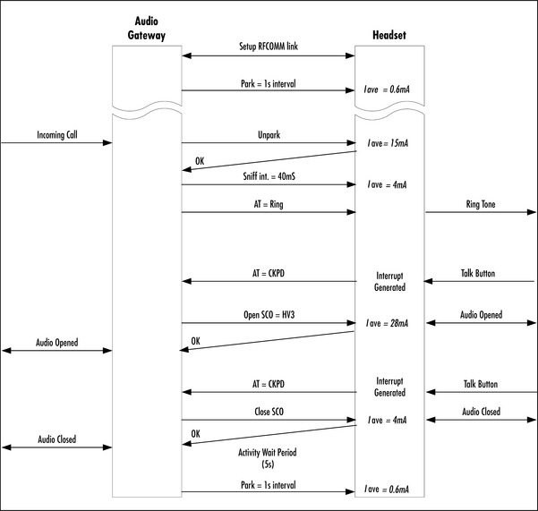
Assessing Battery Life
As we are now acutely aware, a Bluetooth device consumes current, and thus can have an influence on the battery life of any Bluetooth-enabled product. For products with powerful batteries inherent to their normal use, a laptop being the primary example, it will not be a significant issue. For smaller products like mobile phones and PDAs, it could impact on the overall time available for use. We have examined the power consumption on the headset and AG scenario, which is restricted in its functionality, but a multifunctional product like a PDA will have many varying needs for power, dependant upon what activity it is involved in—exchanging a business card, waiting for an e-mail, or Web browsing will all involve different connection models. We will now consider this in a “real-life” situation. To try to get an objective view of the effect on battery life of the Bluetooth functionality in a PDA, it is necessary for us to make some assumptions. These assumptions are variables but will give us a viable model to consider.
Let us assume that when the PDA is on (with the Bluetooth unit fully powered and operational for eight hours per day), the number of times it is used are limited to:
![]() The exchange of nine business cards
The exchange of nine business cards
![]() Two 30-minute presentations using the PDA as a radio mouse
Two 30-minute presentations using the PDA as a radio mouse
For the purpose of modeling power consumption, we need to define a number of states that the Bluetooth device could be in, and for each state, note the power consumption:
![]() State 1: Inactive The device is powered, with clocks running and ready to receive commands over HCI. It has no active connections. Consumption average = 50μA
State 1: Inactive The device is powered, with clocks running and ready to receive commands over HCI. It has no active connections. Consumption average = 50μA
![]() State 2a: Discoverable and Connectable The device is performing Inquiry Scan and R1 Page Scan every 1.28 seconds. The PDA software will probably require human input to put it into this mode. A timeout will return it to the inactive state after some time if no connection is made, perhaps after 1 minute. Consumption average = 1.3mA
State 2a: Discoverable and Connectable The device is performing Inquiry Scan and R1 Page Scan every 1.28 seconds. The PDA software will probably require human input to put it into this mode. A timeout will return it to the inactive state after some time if no connection is made, perhaps after 1 minute. Consumption average = 1.3mA
![]() State 2b: Connectable but not Discoverable The parameters are the same as state 2a, except that only Page Scan is enabled. Consumption average = 0.6mA
State 2b: Connectable but not Discoverable The parameters are the same as state 2a, except that only Page Scan is enabled. Consumption average = 0.6mA
![]() State 3: Paging The master of the piconet has to page a known slave in order to establish the baseband connection. The time this takes depends on the duty cycle of the slave device. We will assume that the slave is using the parameters described in State 2b, in which case, the mean time to connect is 1.5 seconds. Consumption = 41mA
State 3: Paging The master of the piconet has to page a known slave in order to establish the baseband connection. The time this takes depends on the duty cycle of the slave device. We will assume that the slave is using the parameters described in State 2b, in which case, the mean time to connect is 1.5 seconds. Consumption = 41mA
![]() State 4: Connection establishment and parameter negotiation Once a baseband connection is established, the slave and the master transmit or receive in nearly all slots. There may be power control, authentication, SDP database searches and other management traffic before the link is fully established. This takes on the order of 250 milliseconds (ms), determined by the reaction times of the host. Consumption = 47mA
State 4: Connection establishment and parameter negotiation Once a baseband connection is established, the slave and the master transmit or receive in nearly all slots. There may be power control, authentication, SDP database searches and other management traffic before the link is fully established. This takes on the order of 250 milliseconds (ms), determined by the reaction times of the host. Consumption = 47mA
![]() State 5a: Connected, low latency The device is a slave in a piconet (in sniff mode). The latency before data flows can be up to 40 ms, but the mean is 20. The latency is programmable. Consumption = 4mA for a 40ms sniff interval.
State 5a: Connected, low latency The device is a slave in a piconet (in sniff mode). The latency before data flows can be up to 40 ms, but the mean is 20. The latency is programmable. Consumption = 4mA for a 40ms sniff interval.
![]() State 5b: Connected, high latency The device is a slave in a piconet, in sniff or park mode. The latency before data flows can be up to 1.28 seconds, but the mean is 0.64 seconds. The latency is programmable between zero and 42 seconds.1 second is a usual compromise. Consumption = 0.5mA for 1.28 second sniff or beacon interval.
State 5b: Connected, high latency The device is a slave in a piconet, in sniff or park mode. The latency before data flows can be up to 1.28 seconds, but the mean is 0.64 seconds. The latency is programmable between zero and 42 seconds.1 second is a usual compromise. Consumption = 0.5mA for 1.28 second sniff or beacon interval.
![]() State 6: Data transfer in progress We assume a UART connection. The consumption depends on packet rate and whether the unit is a master or a slave. However, with appropriate choices of sniff parameters, the slave and master will have similar consumption. Consumption = 15mA for an ACl link with a baud rate of 115k2.
State 6: Data transfer in progress We assume a UART connection. The consumption depends on packet rate and whether the unit is a master or a slave. However, with appropriate choices of sniff parameters, the slave and master will have similar consumption. Consumption = 15mA for an ACl link with a baud rate of 115k2.
With these states defined, we can now examine use of the PDA in specific activities to determine what the power consumption is expected to be:
Web browsing The user initiates connection to an access point, and the PDA enters State 3 and then State 4. Once connected to the access point, an IP connection is made to the Internet. The slave listens in every slot by default but transmits infrequently. It may request sniff mode; a mean latency of 20ms is appropriate and will dramatically reduce consumption during the time, assume 10 seconds, during which the URL is being searched for. This is State 5a. While data is transferred, assume a mean transfer rate of 24 Kbps, limited by the Internet (the slower this is, the longer it will take, and hence the more pessimistic the result). Assume 90k of bytes transfer, comprising 2 or 3 GIF or JPEG files and one HTML page. Thus, it is in State 6 for 3.84 seconds. Following the data transfer, the device returns to State 5a for a time (e.g., 10 seconds), and then to State 5b if no more traffic is seen. After a further timeout period (for example, 120 seconds), it disconnects and returns to State 1.
Business card or file exchanges with another PDA The users put one PDA into discoverable mode, State 2a, and the other initiates a connection, entering State 3 and leading to State 4. For this analysis, we will consider the slave only. After connection establishment, the data transfers at the ACL data rate allowed by the UART, the filing systems and the upper layer stacks on the two PDAs. Assume a low speed UART, 38k4 and a small file; 1000 bytes is typical for a business card or diary synchronization. The device is thus in State 6 for approximately 0.3 seconds. Following the data transfer, the connection is broken and the device goes to State 2b for 60 seconds. After 60 seconds, it returns to State 1. Clearly, these timeouts are under the control of the application programmer.
Use as a “cordless mouse” (to control a PowerPoint presentation, for instance) The user initiates connection to the PC, and the device enters State 3 and then State 4. Typically, the PC will request a role switch, become master and put the device into State 5a. This lasts the length of the session; there is no timeout. Let us assume a 30-minute presentation, after which the user ends the session and the device returns to State 1.
“Unconscious” synchronization The purpose of this use case is to ensure that the diary or e-mail inbox is always up to date. The PDA runs a daemon. Every so often (5 minutes) it tries to connect to the access point(s) it is paired with, by entering States 3 and then 4. An alternative scenario is for the PDA to do an Inquiry to look for public access points instead, or in addition to the ones it is already paired with. The slight extra traffic required for this is ignored here. Once connected, an IP connection to the appropriate server is made. The slave listens in every slot by default, but transmits infrequently. It may request sniff mode: a mean latency of 20ms is appropriate and will reduce consumption during the time the database is being searched, so the master should put the PDA into State 5a. Let us assume the connection is up for 2 seconds while the server responds, and the data to be transferred, when there is some, is 30K. Further assume that there is new data only once per hour. Thus, when there is new data, the PDA is in State 6 for about 3 seconds, assuming a UART speed of 115k2 baud. After the data, if any, is transferred, the application disconnects and the unit returns to State 1 until the next time it is scheduled by the daemon.
Table 1.6 illustrates the actual power consumption for each of the specific activities previously listed. The model assumes a Class 2 device is used based on CSR’s BlueCore2. We must note that there are many variables in each case, and this is only recommended as a model to provide us with some guidance to enable us to determine the effect of Bluetooth technology within a multifunctional device such as a PDA. It is apparent from this table that the proportion of the time that data is being transmitted or received is low, and that the average current consumption is dominated by the time spent in power saving modes.
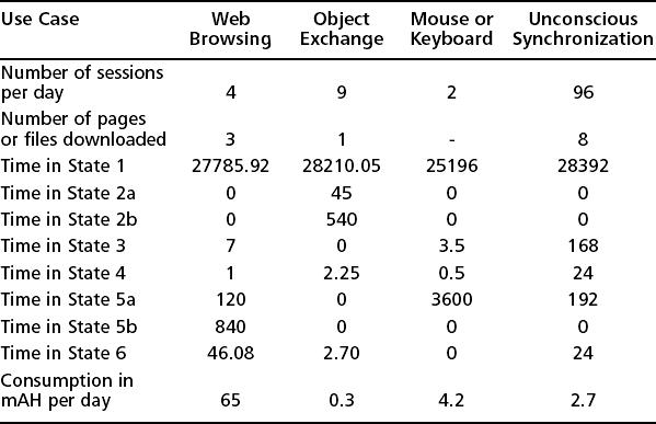
The application program, which is above the Bluetooth specified profiles, determines the efficiency of the use of power saving modes and will be a very important differentiator between manufacturers or software providers. This clearly illustrates the importance of the application programmer being aware of hardware performance issues.
Summary
We began this chapter by examining the factors that may influence whether a product is a suitable candidate for becoming Bluetooth-enabled. The answer is that a device is suitable if data rates of a few hundred kilobits per second are adequate, if it can tolerate short outages in the communications link, if instant connections are not needed, if it can cope with the power consumption of the Bluetooth system, if a range of 100m or less is adequate, and if Bluetooth technology will add end-user value by increasing usability or functionality.
It is all very well to talk of “adding end-user value” but sometimes it is not obvious how that can be achieved, so it is important to consider how Bluetooth technology can add value to various products. The primary value add is through enabling unconscious connectivity, through the ability to seamlessly connect devices without lengthy software installation and configuration.
A product that misses its market is no good to anyone; time factors must also be examined when implementing a Bluetooth device. There is a significant learning curve, and development takes time. Finally, qualification and type approval are necessary before a product can go to market. These factors may mean that adding Bluetooth wireless technology may not be compatible with your product’s development cycle.
Before deciding to add Bluetooth capability to your product, you must be aware of the performance limitations of wireless links. It can take ten seconds to find a Bluetooth device and the same again to connect with it. Once connected, data rates in the hundreds of kilobits are to be expected, but these may be reduced drastically by interference. Latency (delay) on the link is likely to be significantly higher than for wired links.
Before choosing hardware, it is wise to assess the features which Bluetooth technology offers, decide whether you need them in your product, and whether they should be enabled by default. Security features can make it difficult to establish links, but offer privacy when enabled. Low power may not be needed by your product, but you will still need it if you are likely to connect with devices which require low power modes.
Once the decision to implement is taken and you are broadly familiar with the criteria for choosing between Bluetooth solutions, there are many options for hardware and software. The protocol stack on a chip can stop at a host controller interface allowing the higher layers of the Bluetooth protocol stack to run on a separate host processor. Alternatively, the whole stack can be embedded on a Bluetooth chip/chip set. In the latter case, the application could be run on the Bluetooth chip, or on a host device.
When looking at hardware implementation, there are many more options to consider. Either a single chip or a chipset incorporating multiple chips can be chosen. Factors which can influence chip/chip set choice include available space, power consumption, and, of course, price.
Once the silicon is chosen, you must decide upon a design strategy: whether to design your own PCB, or use a prequalified module. A module is undoubtedly the faster and easier option, but your own PCB can give you more flexibility in component placement, and for very high-volume products will be cheaper in the long term.
Finally, you may have to consider batter technology. Obviously, not an issue for anything connected to the mains, but many Bluetooth devices will be handheld and will require batteries. Bluetooth subsystems will drain the battery when active, but the good news is that most of the time they are not active, and there are many long life battery technologies available which are adequate for the power requirements of the Bluetooth subsystem.
Many of the issues in this chapter may seem to be the province of the hardware designer, and you might wonder why they are included in a book on applications. We have seen, however, that hardware choices influence the available features used by software, so it makes sense for our introductory chapter to take a holistic view of Bluetooth products.
Solutions Fast Track
![]() You know Bluetooth technology is a good idea if your product satisfies the following six criteria:
You know Bluetooth technology is a good idea if your product satisfies the following six criteria:
Investigating Product Performance
Deciding How to Implement
![]() Should your stack be hosted, embedded with application on host, or fully embedded?
Should your stack be hosted, embedded with application on host, or fully embedded?
![]() Should you design your own PCB (cheap in volume), or buy in a module (faster and easier)?
Should you design your own PCB (cheap in volume), or buy in a module (faster and easier)?
![]() Battery—if your product is not mains-powered, consider the impact of time spent in different modes on the battery life. Constantly running in scan modes might give you fast connection time, but it will also rapidly drain your batteries. Setting short windows of activity can give almost equivalent performance, and greatly extend your battery life.
Battery—if your product is not mains-powered, consider the impact of time spent in different modes on the battery life. Constantly running in scan modes might give you fast connection time, but it will also rapidly drain your batteries. Setting short windows of activity can give almost equivalent performance, and greatly extend your battery life.
Frequently Asked Questions
The following Frequently Asked Questions, answered by the authors of this book, are designed to both measure your understanding of the concepts presented in this chapter and to assist you with real-life implementation of these concepts. To have your questions about this chapter answered by the author, browse to www.syngress.com/solutions and click on the “Ask the Author” form.
Q: Should I embed the whole stack, or use the host controller interface?
A: This depends on whether you have a host processor with spare resources available. If you have an application which runs on a host device, such as a PC with a powerful processor and lots of memory, then you should run the upper protocol stack on the host and connect to the Bluetooth subsystem using the Host Controller Interface. If you have an application like a headset where your existing device has no processor at all, then you should run the whole Bluetooth solution lower stack, upper stack, and application on one processor to save power, cost, and space. If you have a host with limited resources, such as a mobile phone, you may do best taking an intermediate approach and running the whole stack on the Bluetooth processor instead of running the application on your host processor.
Q: Which hardware solution is for me? A complete prequalified module or a chip?
A: This is dependant upon what your primary design constraint is—cost, time-to-market or PCB real estate—and the recourses you have available. The chip/chip set designed onto your product motherboard will ultimately be the most cost effective option per unit and afford you the smallest footprint but you will require RF design skills and equipment and can encounter significant problems with PCB layout, affecting the performance of your design. This approach also requires that you undergo all of the stringent qualification tests—the chip/chip set you use will ultimately be prequalified, but you will need to perform all the RF tests on your hardware. The module approach offers a faster time-to-market, but the cost overhead per unit will be increased and you will be limited to functionality.
If you need to get to market in a hurry, then a module is probably the way to go. If you have time, development resources with knowledge of radio hardware, and you are anticipating very high volumes for your product, then a chip may be the best option.
Q: Generally, what is the range of battery life?
A: This depends upon the product functionality. Power consumption is much higher when either transmitting or receiving, so the longer you expect your product to be in these states the shorter the battery life. Clever power management design, battery monitoring and use of the Bluetooth power saving modes will all contribute to reducing power consumption.