Chapter 5
Modulation/Demodulation
5.1 Introduction
In order to transmit a digital signal over a body area communication band, the digital signal is often impressed onto a carrier signal. The corresponding process is called modulation in which the digital information signal varies one or more properties of the carrier signal, including amplitude, phase and its frequency. The inverse process of modulation is called demodulation where the original digital information is extracted from the modulated carrier signal. In this chapter, we will describe summarily the feasible modulation and demodulation schemes in body area communications. For various available frequency bands described in Chapter 1, different schemes will be covered. Moreover, based on the body area communication channel characteristics, improvements and simplifications on the receiver structure will also be introduced.
In digital modulation and demodulation, the carrier signal is typically a high frequency sinusoid waveform, while a pulse train may also be utilized in wideband communications. The digital signal may be either binary with two levels or M-ary with multiple levels where each level will represent a discrete pattern of information bits. The fundamental digital modulation methods include amplitude-shift keying (ASK), frequency-shift keying (FSK), and phase-shift keying (PSK). There are also various variations based on these three fundamental modulation schemes. Note that these modulation schemes are essentially narrow-band schemes in which the bandwidth of the modulated signal depends on the bandwidth of the baseband signal. These fundamental narrow-band schemes are well qualified for MICS band, ISM band or HBC band communication. In addition to the fundamental modulation methods, wideband schemes required in certain body area communication scenarios using UWB band will also be covered in this chapter. In fact, two typical UWB schemes, impulse radio UWB (IR-UWB) and multi-band orthogonal frequency-division multiplexing (MB-OFDM), will be presented in this chapter. For UWB communication, the commonly used receivers are based on the pulse energy detection or correlation demodulation with the template waveform. This still applies in body area UWB communications. However, as described in Chapters 2 and 4, the complicated transmission mechanisms in the body area will give rise to a multipath affected propagation channel so that a received signal may end up being the superimposition of several attenuated, delayed, time-varying and eventually distorted replicas of a transmitted signal. Given the body area multipath channel model characteristics derived in Chapter 4, RAKE reception comes in handy to counter the effects of multipath propagation, which could very well result in better communication performance in a multipath environment than in a “clean” environment. In addition, diversity reception can be applied at the receiver to improve the reception performance via multiple receivers/antennas as well as different polarizations.
In this chapter, the modulation schemes for digital shift keying as well as IR-UWB and MB-OFDM will be described first, followed by the corresponding demodulation schemes and error probability analysis. RAKE reception will be separately presented and the error probability with RAKE receiver in body area multipath channel will be given in detail. Finally, we will present the diversity reception application in the in-body communications where multiple receivers with different optimizations will be applied and the diversity effect will be presented in Chapter 6.
5.2 Modulation Schemes
5.2.1 ASK, FSK and PSK
In digital modulation, a continuous carrier signal is modulated by a discrete digital signal. There are three fundamental modulation schemes in digital modulation: ASK, FSK and PSK. They make use of the amplitude, frequency and phase of the carrier signal, respectively, to transmit the digital baseband signal.
In ASK, the amplitude of the carrier signal varies in accordance with the digital modulating signal. The time-domain ASK signal can be expressed in the form:
(5.1) ![]()
where ![]() is the baseband signal waveform,
is the baseband signal waveform, ![]() is the signal interval,
is the signal interval, ![]() is the carrier angular frequency, an is the amplitude of the digits and
is the carrier angular frequency, an is the amplitude of the digits and ![]() is the amplitude of the carrier signal. The simplest form is the binary ASK, in which the carrier signal acts as an On or Off switch via the binary logics “1” and “0.” In the modulated signal, logic “1” is represented by the presence of a carrier and logic “0” is represented by the absence of a carrier, thus giving on/off keying (OOK) operation. The OOK signal is represented by
is the amplitude of the carrier signal. The simplest form is the binary ASK, in which the carrier signal acts as an On or Off switch via the binary logics “1” and “0.” In the modulated signal, logic “1” is represented by the presence of a carrier and logic “0” is represented by the absence of a carrier, thus giving on/off keying (OOK) operation. The OOK signal is represented by
(5.2) ![]()
![]()
Figure 5.1 Typical waveform of binary ASK or OOK
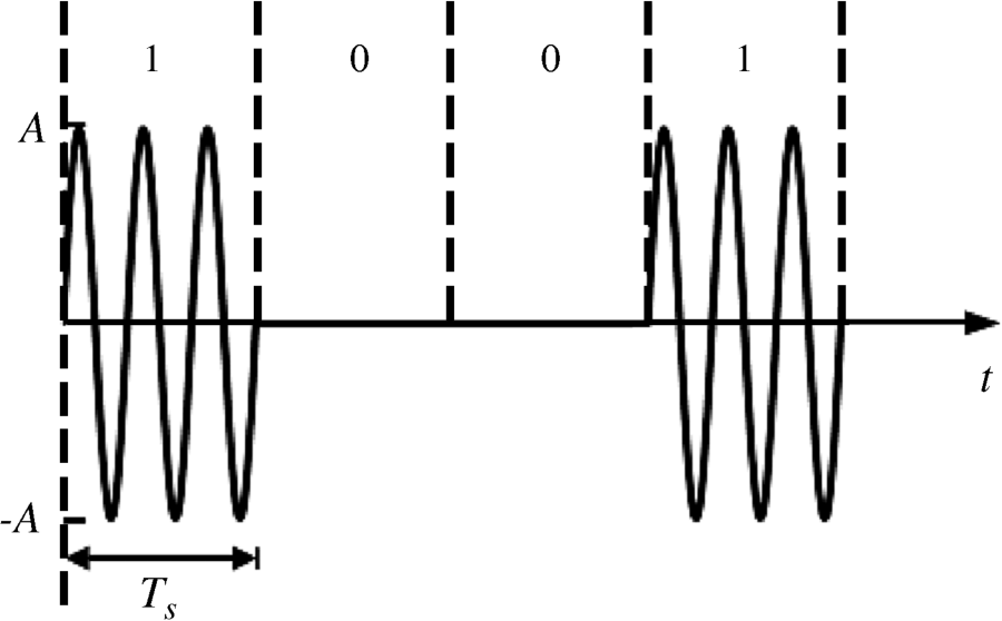
A typical OOK waveform is shown in Figure 5.1.
For the M-ary ASK (MASK) signal, the carrier amplitude has ![]() possible values rather than two digits in OOK, which means
possible values rather than two digits in OOK, which means ![]() . Each amplitude
. Each amplitude ![]() is transmitted in one symbol interval Ts. The modulation of MASK is similar to the binary ASK. Generally, the binary series is divided into sets of
is transmitted in one symbol interval Ts. The modulation of MASK is similar to the binary ASK. Generally, the binary series is divided into sets of ![]() bits,
bits, ![]() and then transformed to
and then transformed to ![]() baseband signal waveforms. The
baseband signal waveforms. The ![]() baseband signal waveforms act as the input modulating signals. The amplitude of the modulated signal is proportional to the amplitude of the baseband signal waveform.
baseband signal waveforms act as the input modulating signals. The amplitude of the modulated signal is proportional to the amplitude of the baseband signal waveform.
In FSK, the frequency of the carrier signal varies in accordance with the digital modulating signal. Similarly, the time-domain binary FSK signal can be expressed in the form
(5.3) ![]()
where the carrier frequencies ![]() and
and ![]() change with the modulating signal
change with the modulating signal ![]() and its anti-code
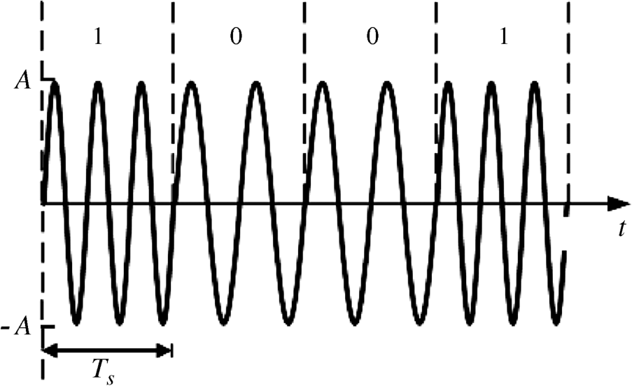
and its anti-code ![]() . If the binary “1” corresponds to carrier angular frequency ω1 and “0” corresponds to carrier angular frequency ω2, with the simplest case that g(t) is the single rectangular pulse, a typical BFSK waveform is then as shown in Figure 5.2.
. If the binary “1” corresponds to carrier angular frequency ω1 and “0” corresponds to carrier angular frequency ω2, with the simplest case that g(t) is the single rectangular pulse, a typical BFSK waveform is then as shown in Figure 5.2.
Figure 5.2 Typical waveform of FSK
In M-ary FSK (MFSK), the ![]() symbols can be expressed as
symbols can be expressed as
(5.4) ![]()
where ![]() is the signal energy in one symbol interval
is the signal energy in one symbol interval ![]() and
and ![]() is the carrier angular frequency with
is the carrier angular frequency with ![]() possible values. Generally, we have the difference of the carrier frequency
possible values. Generally, we have the difference of the carrier frequency ![]() (where N is a positive integer), which means
(where N is a positive integer), which means ![]() signals are orthogonal to each other.
signals are orthogonal to each other.
Moreover, a special type of BFSK with modulation index of 0.5 is known as the minimum shift keying (MSK). The modulation index of 0.5 corresponds to a frequency difference ![]() , which is the smallest possible difference if the signals of the two frequencies are to be orthogonal over one bit interval. The advantage of MSK is that there are no phase discontinuities in the modulated signal waveforms because the frequency variations occur at the carrier zero crossing points. Thus it is a continuous phase scheme. Prior to the MSK modulation, a Gaussian filter is often used to further reduce the bandwidth of a baseband pulse train. This is known as Gaussian filtered MSK or GMSK. GMSK gives a smoothed phase trajectory of MSK signals and thus limits the instantaneous frequency variations. This feature results in a narrower bandwidth than for MSK.
, which is the smallest possible difference if the signals of the two frequencies are to be orthogonal over one bit interval. The advantage of MSK is that there are no phase discontinuities in the modulated signal waveforms because the frequency variations occur at the carrier zero crossing points. Thus it is a continuous phase scheme. Prior to the MSK modulation, a Gaussian filter is often used to further reduce the bandwidth of a baseband pulse train. This is known as Gaussian filtered MSK or GMSK. GMSK gives a smoothed phase trajectory of MSK signals and thus limits the instantaneous frequency variations. This feature results in a narrower bandwidth than for MSK.
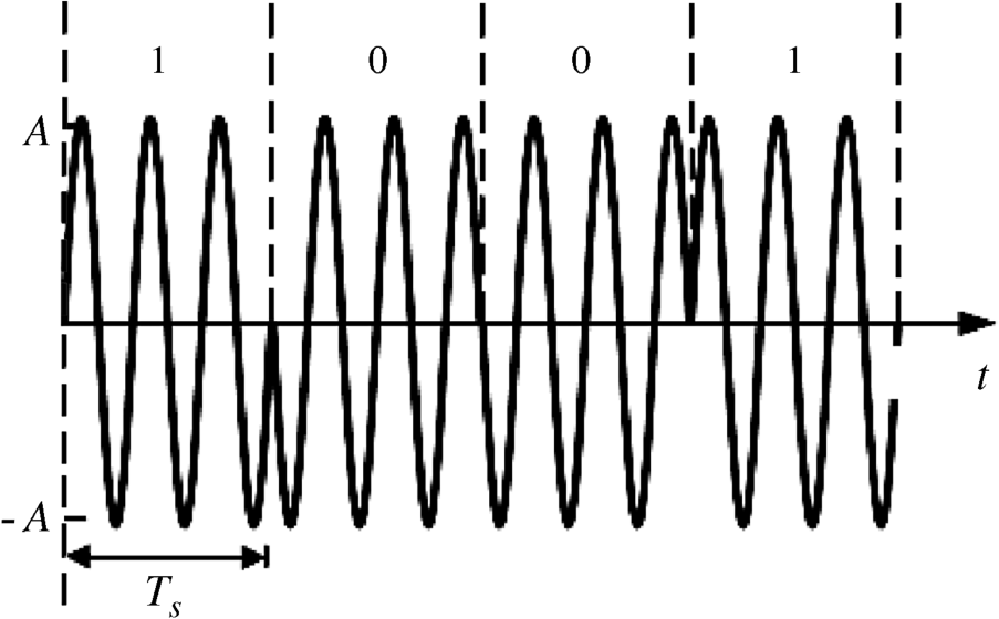
In PSK, the phase of the carrier signal varies in accordance with the digital modulating signal. In binary PSK (BPSK), the binary “0” and “1” are generally represented by phase 0° or 180°, respectively. The time-domain BPSK signal can be expressed in the form
(5.5) ![]()
where an is different from that in binary ASK and binary FSK. Here
Therefore, in one signal interval ![]() , given the
, given the ![]() is a rectangular pulse with width
is a rectangular pulse with width ![]() , we have
, we have
(5.6) ![]()
Figure 5.3 shows a typical waveform for BPSK.
Figure 5.3 Typical waveform of BPSK
For M-ary PSK (MPSK) signal, the carrier phase has ![]() possible values and the
possible values and the ![]() symbols can be expressed as
symbols can be expressed as
(5.7) ![]()
where ![]() is the signal energy in one symbol interval
is the signal energy in one symbol interval ![]() and
and ![]() is the carrier phase with
is the carrier phase with ![]() possible values.
possible values.
5.2.2 IR-UWB
The most common and traditional UWB signal uses extremely short pulses with duration on the order of nanoseconds to transmit information, rather than continuous waveforms, with typically no RF modulation. This transmission technique has been extensively used and goes under the name of impulse radio (IR). IR-UWB is characterized by a low duty cycle of pulses so that the transmitted power can be very small. Moreover, carrier modulation is not required and therefore there is no up and down conversion. A RF power amplifier is also not needed. As a result, the IR-UWB transceiver has a simple architecture with low cost. For IR-UWB, the pulses are the information carrier and the way in which the information data modulate the pulses may vary. OOK modulation, pulse position modulation (PPM) and pulse amplitude modulation (PAM) are the commonly adopted modulation schemes in IR-UWB. In addition to modulation and in order to shape the spectrum of the generated signal, the data bits are often encoded using pseudorandom or pseudo-noise (PN) codes. The period and duty cycle of the pulse will vary in a pseudorandom manner under the control of an encoded sequence. The encoded data symbols will introduce a time delay on generated pulses leading to the so-called time-hopping UWB (TH-UWB). Time hopping is one of the spread spectrum techniques. Combining it with PPM is known as the PPM-TH-UWB. Another common spread spectrum technique is the amplitude modulation of basic pulses by the encoded data symbols, that is, the so-called PAM direct-sequence UWB (PAM-DS-UWB). The generation of the common OOK-UWB, PPM-TH-UWB and PAM-DS-UWB signals will be discussed in the next section.
The system model for an IR-UWB transmitter is shown in Figure 5.4 (Benedetto and Giancola, 2004). The binary information data are first encoded by a channel coder, followed by a transmission coder, and then modulated by an OOK, PPM or PAM, and finally transmitted via the antenna as a pulse train. The channel coder adopts the repetition coder which is easy to implement although it is a relatively simple method of encoding data across a channel. The transmission coder provides a pseudorandom code to encode the position or the amplitude of the pulses.
Figure 5.4 IR-UWB transmission flow chart
Figure 5.5 shows the transmission scheme for IR-UWB with OOK modulation. When the information bit is “1” the UWB pulses are transmitted, while nothing is transmitted when the bit is “0”. This scheme is especially effective for low-power design but it suffers from low SNR within the bit “0” duration because no signal energy is transmitted within that duration. A useful method to cope with this problem is to encode the bits “1” and “0” with a code containing both “1” and “0.” For example, if we encode the bits “1” and “0” into {1011000} and {0100111}, and then perform the OOK modulation according to the encoded codes, we can always have some pulses transmitted both within the bit “1” and bit “0” periods. Figure 5.6 shows such an encoded OOK modulated signal waveform.
Figure 5.5 Transmitter for IR-UWB with OOK modulation
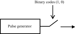
Figure 5.6 An example of an IR-UWB signal with encoded OOK modulation
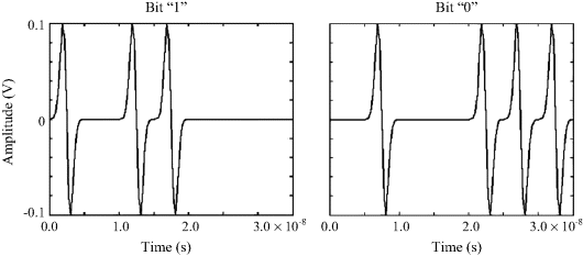
Figure 5.7 shows the transmission scheme for a PPM-TH-UWB signal. The input binary sequence at a data rate of 1/![]() bits/s (bps) is first repeated
bits/s (bps) is first repeated ![]() times and results in a binary sequence at a data rate of 1/
times and results in a binary sequence at a data rate of 1/![]() bps. The pseudorandom TH code, acting as the transmission code, applies an integer-valued code
bps. The pseudorandom TH code, acting as the transmission code, applies an integer-valued code ![]() to the binary sequence. The generic element of the TH code
to the binary sequence. The generic element of the TH code ![]() is an integer value with uniform distribution on the interval
is an integer value with uniform distribution on the interval ![]() where
where ![]() represents the cardinality of the TH code. The bit interval
represents the cardinality of the TH code. The bit interval ![]() is divided into
is divided into ![]() chips with each chip time
chips with each chip time ![]() . The periodicity of the TH code is represented by
. The periodicity of the TH code is represented by ![]() and the periodicity of the TH code commonly coincides with the length of the repetition code, that is,
and the periodicity of the TH code commonly coincides with the length of the repetition code, that is, ![]() . The coded real-valued sequence then enters the PPM modulator. The modulator generates a sequence of Dirac pulses at a rate of
. The coded real-valued sequence then enters the PPM modulator. The modulator generates a sequence of Dirac pulses at a rate of ![]() pulses/s. These pulses locate at times
pulses/s. These pulses locate at times ![]() where
where ![]() is the nominal pulse position while
is the nominal pulse position while ![]() is the time shift introduced by the TH code. After the PPM modulation, the pulses occur at times
is the time shift introduced by the TH code. After the PPM modulation, the pulses occur at times ![]() where ε is the time shift introduced by PPM modulation and
where ε is the time shift introduced by PPM modulation and ![]() is the binary sequence following the code repetition coder. In general the time shift introduced by the PPM modulator is usually much smaller than the shift introduced by the TH code, that is,
is the binary sequence following the code repetition coder. In general the time shift introduced by the PPM modulator is usually much smaller than the shift introduced by the TH code, that is, ![]() . The last block is the pulse shaper with impulse response
. The last block is the pulse shaper with impulse response ![]() .
.
Figure 5.7 Transmission scheme for a PPM-TH-UWB signal
Based on the above system, the PPM-TH-UWB signal can be expressed as:
(5.8) ![]()
In the PPM-TH-UWB signal, we can note that pulses occur at times (![]() ). Figure 5.8 shows an example of a PPM-TH-UWB signal with binary bits [1, 0] and TH code [1 1 1 2]. Note that
). Figure 5.8 shows an example of a PPM-TH-UWB signal with binary bits [1, 0] and TH code [1 1 1 2]. Note that ![]() ,
, ![]() ,
, ![]() ,
,![]() ,
, ![]() , and ε = 0.25 ns.
, and ε = 0.25 ns.
Figure 5.8 Example of a PPM-TH-UWB signal with binary bits [1, 0] and TH code [1 1 1 2]
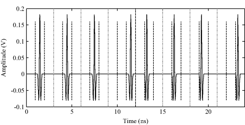
As noted, the binary information is encoded in the pulse position, and this will induce an inherent disadvantage to PPM as it is sensitive to the multipath affected channel. This is because in multipath affected channels the multiple paths of each transmitted pulse will interfere with the accurate determination of the pulse position. That is, the signal energy associated with each symbol is spread out in time and therefore the transmitted symbol will occur in the next symbol period and this will result in the inter-symbol interference in the receiver.
Similarly to PPM-TH-UWB, the transmission scheme for a PAM-DS-UWB signal is shown in Figure 5.9. After the code repetition coding, the binary sequence is first converted into a positive- and negative-valued sequence. The transmission coder applies a DS code ![]() to the antipodal sequence
to the antipodal sequence ![]() . The DS code
. The DS code ![]() has periodicity
has periodicity ![]() and
and ![]() is commonly assumed to be equal to
is commonly assumed to be equal to ![]() . Like the PPM modulator, the PAM modulator generates a sequence of Dirac pulses at a rate of
. Like the PPM modulator, the PAM modulator generates a sequence of Dirac pulses at a rate of ![]() pulses/s, while these pulses locate at times
pulses/s, while these pulses locate at times ![]() . Finally the output of the modulator enters the pulse shaper with impulse response
. Finally the output of the modulator enters the pulse shaper with impulse response ![]() .
.
Figure 5.9 Transmission scheme for a PAM-DS-UWB signal
The PAM-DS-UWB signal can be expressed as
(5.9) ![]()
Note that the definitions of ![]() and
and ![]() are the same as in the above PPM-TH-UWB signal except that the
are the same as in the above PPM-TH-UWB signal except that the ![]() sequence here is a positive- and negative-valued sequence. In the PAM-DS-UWB signal, all pulses are located at time
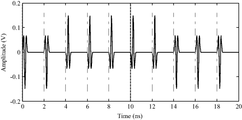
sequence here is a positive- and negative-valued sequence. In the PAM-DS-UWB signal, all pulses are located at time ![]() . Figure 5.10 shows an example of a PAM-DS-UWB signal with binary bits [1, 0] and DS code [−1 −1 1 1 1]. Note that
. Figure 5.10 shows an example of a PAM-DS-UWB signal with binary bits [1, 0] and DS code [−1 −1 1 1 1]. Note that ![]() ,
, ![]() ,
, ![]() , and
, and![]() .
.
Figure 5.10 Example of a PAM-DS-UWB signal with binary bits [1, 0] and DS code [−1 −1 1 1 1]
5.2.3 MB-OFDM
Based on the UWB definition by the FCC (FCC, 2002), if the bandwidth is larger than 500 MHz, it is also a UWB signal. The multi-band (MB) solution divides the whole UWB band from 3.1 to 10.6 GHz into smaller frequency sub-bands of at least 500 MHz. In each sub-band, different modulation schemes can be adopted for data modulation. The modulation can be any form of modulation used with digital data, but the most common modulations are BPSK, quadrature PSK (QPSK), and quadrature amplitude modulation (QAM). The sub-band bandwidth can be occupied by an appropriate data rate. The most common approach is OFDM. The basic idea of OFDM is to use a large number of parallel closely spaced orthogonal subcarriers instead of a single wide-band carrier to transmit information. Each subcarrier corresponds to a quadrature modulation of a signal. These subcarriers are equally spaced by ![]() in the frequency domain. If
in the frequency domain. If ![]() is the time to transmit each symbol, then
is the time to transmit each symbol, then ![]() can keep the orthogonality between different subcarriers. This is because the resulting sinc frequency response function of the signals is such that the first nulls occur at the subcarrier frequencies on the adjacent channels. Orthogonal subcarriers all have an integer number of cycles within the symbol period.
can keep the orthogonality between different subcarriers. This is because the resulting sinc frequency response function of the signals is such that the first nulls occur at the subcarrier frequencies on the adjacent channels. Orthogonal subcarriers all have an integer number of cycles within the symbol period.
In an OFDM modulator, the input serial binary sequence is first divided into multiple data streams of K bits to generate blocks of N symbols. The N symbols have L possible values, and ![]() hence holds. Each symbol will then modulate a different orthogonal subcarrier. The outputs of all the modulators are linearly summed, and the result is the signal to be transmitted. It could be up-converted and amplified if needed. A guard interval TG is introduced at the beginning of each symbol to eliminate the inter-symbol interference in a multipath propagation channel. The total OFDM symbol duration is thus
hence holds. Each symbol will then modulate a different orthogonal subcarrier. The outputs of all the modulators are linearly summed, and the result is the signal to be transmitted. It could be up-converted and amplified if needed. A guard interval TG is introduced at the beginning of each symbol to eliminate the inter-symbol interference in a multipath propagation channel. The total OFDM symbol duration is thus ![]() . The guard interval is usually a copy of the end section of the OFDM symbol, the so-called cyclic prefix (CP). Appending the CP does not cause any discontinuities and the original frequency of the orthogonal subcarriers still hold. The CP acts as a buffer region where delayed information from the previous symbols can get stored. The receiver has to exclude samples from the CP which is corrupted by the previous symbol when choosing the samples for an OFDM symbol. The reason that the guard interval consists of a copy of the final section of the OFDM symbol is to maintain the carrier synchronization at the receiver. Of course, the flipside of adding the CP is the loss in data rate as we are conveying redundant information. Given that transmission of the CP reduces the data rate, the CP duration should be minimized as much as possible. Typically, the CP duration is determined by the expected duration of the multipath channel in the operating environment. For example, for the indoor wireless multipath channel, the typically expected multipath channel is of around 0.8 μs duration, hence the CP is chosen to be 0.8 μs in the IEEE 802.11a specification. However, for the on-body area UWB multipath channel, the delay spread is around 0.4 ns.
. The guard interval is usually a copy of the end section of the OFDM symbol, the so-called cyclic prefix (CP). Appending the CP does not cause any discontinuities and the original frequency of the orthogonal subcarriers still hold. The CP acts as a buffer region where delayed information from the previous symbols can get stored. The receiver has to exclude samples from the CP which is corrupted by the previous symbol when choosing the samples for an OFDM symbol. The reason that the guard interval consists of a copy of the final section of the OFDM symbol is to maintain the carrier synchronization at the receiver. Of course, the flipside of adding the CP is the loss in data rate as we are conveying redundant information. Given that transmission of the CP reduces the data rate, the CP duration should be minimized as much as possible. Typically, the CP duration is determined by the expected duration of the multipath channel in the operating environment. For example, for the indoor wireless multipath channel, the typically expected multipath channel is of around 0.8 μs duration, hence the CP is chosen to be 0.8 μs in the IEEE 802.11a specification. However, for the on-body area UWB multipath channel, the delay spread is around 0.4 ns.
The complex envelope of the OFDM signal corresponding to a block of N symbols can be expressed as (Benedetto and Giancola, 2004):
(5.10) ![]()
where ![]() is the baseband rectangular waveform with finite duration T
is the baseband rectangular waveform with finite duration T
(5.11) ![]()
and ![]() indicates the point in the constellation and
indicates the point in the constellation and ![]() is the corresponding subcarrier frequency.
is the corresponding subcarrier frequency.
In order to cover a wide bandwidth, hundreds or even thousands of parallel subcarriers might be used. To implement that with hardware is a challenge even with modern semiconductor technology. In fact, the whole process in the OFDM modulator can be accomplished in computer hardware by using the inverse fast Fourier transform (IFFT). The IFFT converts an input signal from the time domain by mapping its baseband frequencies onto their representative phases and amplitudes in preparation for modulation to the passband. All the individual carriers with modulation are in digital form and then subjected to an IFFT mathematical process, creating a single composite signal that can be transmitted. The fast Fourier transform (FFT) at the receiver sorts all the signal components into the individual sine-wave elements of specific frequencies and amplitudes to recreate the original data stream.
The digital representation of the complex envelope is
where ![]() is the sampling period. It represents the samples at multiple
is the sampling period. It represents the samples at multiple ![]() . In fact, the summation item in Equation 5.12 corresponds to the nth element of vector C representing the IFFT of the vector
. In fact, the summation item in Equation 5.12 corresponds to the nth element of vector C representing the IFFT of the vector ![]() , which can be further expressed as:
, which can be further expressed as:
(5.13) ![]()
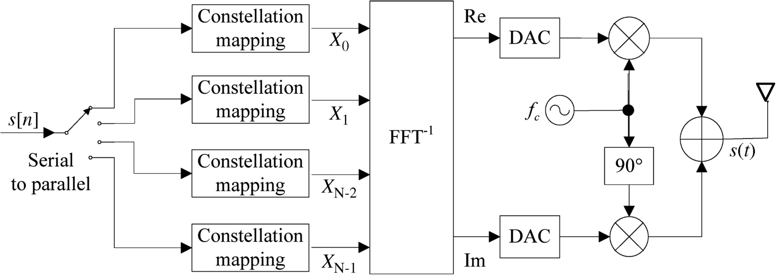
Figure 5.11 shows the block diagram of a MB-OFDM transmitter. A fast serial data stream ![]() is first divided by means of a serial-to-parallel conversion into
is first divided by means of a serial-to-parallel conversion into ![]() parallel slower data streams. Each of the
parallel slower data streams. Each of the ![]() parallel data streams is then mapped to a symbol stream through the digital constellation mapping scheme (QPSK, BPSK, QAM, etc.). And then each symbol set modulates different subcarriers via the IFFT block. The resulting complex time-domain signal is divided into real and imaginary analog components by means of digital-to-analog converters (DACs) and then used to modulate a main RF carrier.
parallel data streams is then mapped to a symbol stream through the digital constellation mapping scheme (QPSK, BPSK, QAM, etc.). And then each symbol set modulates different subcarriers via the IFFT block. The resulting complex time-domain signal is divided into real and imaginary analog components by means of digital-to-analog converters (DACs) and then used to modulate a main RF carrier.
Figure 5.11 Block diagram of an OFDM transmitter
The IEEE 802.15.3a working group provides a higher speed UWB PHY standard ECMA-368 (ECMA, 2005) based on the MB-OFDM solution (IEEE P802.15, 2004). ECMA-368 is a widely adopted international specification for MB-OFDM UWB. The MB-OFDM UWB employs the OFDM technology and interleaves OFDM symbols to hop in frequency domain, the 7.5 GHz bandwidth is segmented into five band groups, each band group having 2–3 sub-bands which occupy 528 MHz. Figure 5.12 shows the officially issued band-group allocation over the 3.1–10.6 GHz band. Information bits are interleaved across all bands to better exploit frequency diversity over the whole frequency spectrum. Although a wide band of frequencies could be used, certain practical considerations limit the frequencies that are normally used for MB-OFDM UWB. Based on existing semiconductor technology, use of the spectrum from 3.1 to 4.8 GHz is considered to be optimal for initial deployments. Limiting the upper bound simplifies the design of the radio and analog front end circuitry as well as reducing interference with other services. Additionally the frequency band from 3.1 to 4.8 GHz, that is, band group 1, is sufficient for three sub-bands of 500 MHz when using MB-OFDM UWB. Band group 1 is divided into three sub-bands and frequency hopping is employed.
Figure 5.12 Diagram of the band-group allocation over the 3.1–10.6 GHz band

Based on the specifications of the ECMA-368 standard, the main parameters to produce a MB-OFDM UWB signal are listed in Table 5.1. As can be seen, each OFDM symbol period of 312.5 ns consists of a guard time of 70.1 ns and an information period of 242.4 ns. The OFDM period is used for transmitting the 100 information symbols and 28 pilot symbols which are used for time synchronization to avoid inter-symbol interference and frequency synchronization to avoid inter-carrier interference. Each symbol of the OFDM block (both data and pilot symbols) modulates the corresponding subcarrier for a period of 242.4 ns, resulting in a frequency spacing of 4.125 MHz. The OFDM bandwidth is thus 528.5 MHz. Figure 5.13 shows two OFDM symbols with the simulation parameters as shown in Table 5.1.
Figure 5.13 Two OFDM symbols with parameters shown in Table 5.1
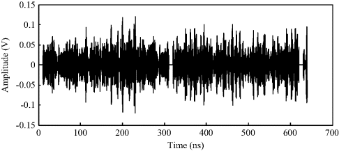
Table 5.1 ofdm simulation parameters from ECMA-368.
| Parameter | Value |
| Number of subcarriers (FFT size) | 128 |
| Number of data subcarriers | 100 |
| FFT sampling frequency (GHz) | 50 |
| Subcarrier frequency spacing (MHz) | 4.125 |
| Symbol interval (ns) | 312 |
| Cyclic prefix duration, Tp (ns) | 60.6 |
| Guard time, TG (ns) | 70.1 |
| Symbol duration, T0 (ns) | 242.4 |
| OFDM bandwidth (MHz) | 528.5 |
| Modulation | QPSK |
| Band group | 1 |
Compared with IR-UWB, the main advantage of the OFDM approach is that the symbol rate in each sub-band can be greatly lowered which can reduce the inter-symbol interference and enhance the ability to resist multipath transmission. Meanwhile, a large number of subcarriers convey multiple low rate symbols simultaneously, which does not reduce the whole data rate.
The straightforward disadvantage of the MB-OFDM is that it is complex, making it more expensive to implement. In addition, MB-OFDM is also sensitive to carrier frequency variations. To overcome this problem, OFDM systems transmit pilot carriers along with the subcarriers for synchronization at the receiver. Another disadvantage is that an MB-OFDM signal has a high peak to average power ratio. As a result, the complex MB-OFDM signal requires linear amplification. This means greater inefficiency in the RF power amplifiers and more power consumption.
5.3 Demodulation and Error Probability
5.3.1 Optimum Demodulation for ASK, FSK and PSK
In a practical digital transmission system, optimum demodulation for a digital modulated signal generally requires maximal SNR and minimal error probability. Under the maximal SNR criterion, the matched filter (MF), as the optimal linear filter, is employed to maximize the SNR in the presence of additive white Gaussian noise (AWGN). The impulse response of the matched filter is the mirror and translation of the input signal and therefore it can be expressed as
(5.14) ![]()
where K is a constant. Its transmission function is proportional to the complex conjugate of the signal spectrum ![]() as in Equation 5.15, hence the name “matched filter”.
as in Equation 5.15, hence the name “matched filter”.
Figure 5.14 gives the schematic diagram of the matched filter demodulation. At the sampling moment ![]() , the output signal reaches the maximum value and the maximum SNR is therefore achieved.
, the output signal reaches the maximum value and the maximum SNR is therefore achieved.
Figure 5.14 Matched filter demodulation

Under the minimal error probability criterion, the correlator is employed which consists of a multiplier and an integrator as shown in Figure 5.15.
Figure 5.15 Correlator demodulation

In fact, the transmitted signal generally occurs in ![]() and therefore in the MF demodulation the output signal in Figure 5.14 can be expressed as:
and therefore in the MF demodulation the output signal in Figure 5.14 can be expressed as:
(5.16) ![]()
When t = Ts, we have
(5.17) ![]()
This expression is equivalent to the correlator demodulation as shown in Figure 5.15. In fact, the MF demodulation and the correlator demodulation are consistent. Therefore, the correlator demodulation is usually taken as the optimum demodulation. Actually, only if the filter (either passband or baseband) is designed on the basis of the MF requirements, the correlator demodulation is the real optimum demodulation.
Figure 5.16 shows a diagram of the optimum demodulation for the ASK signal. It can be seen that a reference carrier has to be generated locally at the receiver.
Figure 5.16 Optimum demodulation for an ASK signal

The optimum demodulation for the FSK signal is similar to that for ASK, but with multiple circuits corresponding to different carrier frequency.
The demodulation of the BPSK signal must employ a local carrier with the same carrier frequency and same phase. The carrier recovery can be achieved based on nonlinear transformation from the modulated signal. Figure 5.17 shows the optimum correlator demodulation for the BPSK signal. There are phase ambiguity problems of the recovered carrier, so differentially encoded BPSK (DBPSK) is often used in practice. The DBPSK signal conveys data based on the relative phase variation instead of the absolute phase of the carrier. This kind of encoding may be demodulated in the same way as for nondifferential PSK but the phase ambiguities can be ignored.
Figure 5.17 Optimum demodulation for a PSK signal

In binary digital demodulation, assuming that the two signals are expressed as ![]() and
and ![]() and the corresponding signal energies during the symbol interval
and the corresponding signal energies during the symbol interval ![]() are
are
(5.18) ![]()
(5.19) ![]()
the correlation coefficient between ![]() and
and ![]() is therefore expressed as:
is therefore expressed as:
(5.20) ![]()
which describes the similarity between the two signals and the ![]() ranges in (−1,1).
ranges in (−1,1).
In optimum demodulation, the bit error probability is (Haykin, 1988)
(5.21) 
where
(5.22) ![]()
is usually named as the Q function and erfc is the complementary error function. N0 is the noise unilateral power spectral density.
If the two signals have the same energy, that is, ![]() where Eb represents the signal energy in one bit, then we have
where Eb represents the signal energy in one bit, then we have
This is the minimal bit error probability for binary modulation in optimum demodulation, either in MF demodulation or correlator demodulation.
For the binary ASK or OOK signal, ![]() ,
, ![]() , therefore we have
, therefore we have
(5.24) ![]()
For the BPSK signal, ![]() and
and ![]() can be derived, based on Equation 5.23, we have
can be derived, based on Equation 5.23, we have
(5.25) ![]()
For the binary FSK signal, if the difference between the two carrier frequencies ![]() and
and ![]() is
is ![]() (where N is a positive integer), then the two signals keep orthogonal and
(where N is a positive integer), then the two signals keep orthogonal and ![]() can be derived, then the bit error probability for the binary FSK signal with
can be derived, then the bit error probability for the binary FSK signal with ![]() is
is
(5.26) ![]()
In another case, if the difference between the two carrier frequencies gets close to infinity, the correlation coefficient ![]() is close to zero too.
is close to zero too.
For the M-ary shift keying signal (M>2), the principle of the optimum demodulation is the same as the binary shift key signal. However, the error probability of M-ary shift keying signal is usually expressed in terms of symbol error probability rather than bit error probability.
The optimum symbol error probability for the MASK signal in correlator demodulation is approximately
(5.27) ![]()
where the signal amplitude Am takes the discrete levels, that is,
(5.28) ![]()
Similarly, the optimum symbol error probability of the MPSK signal is approximately
(5.29) ![]()
when Eb/N0![]() 1.
1.
5.3.2 Noncoherent Detection for ASK, FSK and PSK
The correlator demodulation requires generation of a synchronous reference carrier signal at the receiver. In this sense it is considered to be a coherent detection. Compared with coherent detection, the significant advantage of noncoherent detection is there is no need to generate the reference carrier signal at the receiver, which largely simplifies the receiver structure. Noncoherent detection is a suboptimal demodulation scheme.
For the ASK signal, envelope detection is used to extract the amplitude information of the modulated signal. A half-wave rectifier or full-wave rectifier acts as the envelope detection device. Figure 5.18 shows a diagram of the noncoherent detection scheme for the ASK signal. Actually, noncoherent detection for the ASK signal is more common than the correlator demodulation.
Figure 5.18 Noncoherent detection for an ASK signal

The bit error probability for the binary ASK signal in noncoherent detection can be expressed as
For the binary FSK signal with ![]() , the modulated signals are orthogonal to each other. The two transmitted signals have the same energy if equal amplitude modulation is assumed. The diagram of the noncoherent detection scheme for the FSK signal is shown in Figure 5.19. The bandpass MF corresponds to signals with different frequencies.
, the modulated signals are orthogonal to each other. The two transmitted signals have the same energy if equal amplitude modulation is assumed. The diagram of the noncoherent detection scheme for the FSK signal is shown in Figure 5.19. The bandpass MF corresponds to signals with different frequencies.
Figure 5.19 Noncoherent detection for a FSK signal

The bit error probability for the binary FSK signal in noncoherent detection can be expressed as
It has the same bit error probability as the binary ASK. Actually, Equation 5.30 is the bit error probability expression for any binary orthogonal signal in optimum noncoherent detection.
When the orthogonal MFSK signal is demodulated using the noncoherent detection scheme, the symbol error probability is (Lindsey and Simon, 1973):
(5.32) ![]()
For the BPSK signal, as described in Section 5.3.1, demodulation must use the correlator demodulation while the carrier recovery at the receiver has a phase ambiguity problem. DBPSK is therefore often used in practice (Smith, 1985). Noncoherent detection for the DBPSK signal is shown in Figure 5.20. It takes the delayed signal as the reference signal, in which the delayed period is the symbol interval.
Figure 5.20 Noncoherent detection for a DBPSK signal

The bit error probability for the noncoherent detected DBPSK signal can be expressed as
(5.33) ![]()
Compared with Equations 5.30 and 5.31, it can be seen that the bit error probability for noncoherent detected DBPSK exceeds that for noncoherent detected binary ASK and FSK.
For the M-ary noncoherent detected DBPSK signal, the symbol error probability is (Arthurs and Dym, 1962)
(5.34) 
Figure 5.21 compares the error probability performance of coherent and noncoherent detection of binary ASK, FSK and PSK, respectively. Note that the probability of error for coherent BPSK outperforms that for binary ASK and FSK. At the same bit error probability, the required ![]() is 3 dB lower than for binary ASK and FSK which implies the transmitted signal energy can be cut in half. The error probability for noncoherent FSK is the same as that for noncoherent ASK. The performance of the noncoherent detection is poor compared with coherent detection. At a bit error probability of 10−5, the difference is around 1 dB. The error probability performance of noncoherent DBPSK is also shown in Figure 5.21 and it can be noted that the noncoherent DBPSK is better than noncoherent binary ASK and FSK.
is 3 dB lower than for binary ASK and FSK which implies the transmitted signal energy can be cut in half. The error probability for noncoherent FSK is the same as that for noncoherent ASK. The performance of the noncoherent detection is poor compared with coherent detection. At a bit error probability of 10−5, the difference is around 1 dB. The error probability performance of noncoherent DBPSK is also shown in Figure 5.21 and it can be noted that the noncoherent DBPSK is better than noncoherent binary ASK and FSK.
Figure 5.21 Bit error probability of binary modulation

5.3.3 Optimum Demodulation for IR-UWB
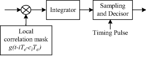
The optimum demodulation for the PPM-TH-UWB and PAM-DS-UWB signal is essentially similar to correlator demodulation for the ASK signal. As shown in Figure 5.22, the optimum demodulation for PPM-TH-UWB consists of a multiplier, an integrator and sampling decisor. The local correlation mask is the TH pulse template ![]() . Through the correlator, the difference induced by the PPM time shift
. Through the correlator, the difference induced by the PPM time shift ![]() can be detected and the transmitted bit can be estimated at the output. If the PPM time shift
can be detected and the transmitted bit can be estimated at the output. If the PPM time shift ![]() is larger than the pulse duration
is larger than the pulse duration ![]() , the two transmitted signals corresponding to bit 1 and bit 0 are orthogonal to each other. For the binary orthogonal PPM signal, the minimal bit error probability can be expressed as follows
, the two transmitted signals corresponding to bit 1 and bit 0 are orthogonal to each other. For the binary orthogonal PPM signal, the minimal bit error probability can be expressed as follows
Figure 5.22 Optimum demodulation for a PPM-TH-UWB signal
where ![]() is the received energy per bit,
is the received energy per bit, ![]() is the received energy per pulse, and
is the received energy per pulse, and ![]() is the code repetition redundancy. Note that at the cost of increasing the number of pulses per bit, the received energy is increased by a factor NS and the bit error probability will consequently reduce. This is the benefit due to the presence of
is the code repetition redundancy. Note that at the cost of increasing the number of pulses per bit, the received energy is increased by a factor NS and the bit error probability will consequently reduce. This is the benefit due to the presence of ![]() pulses per bit from the application of a code repetition coder before modulation.
pulses per bit from the application of a code repetition coder before modulation.
Equation 5.35 is the minimal bit error probability which corresponds to an optimum decision detection. Actually, in the presence of multiple pulses per symbol, two possible decision strategies can be adopted at the receiver. One is the soft decision detection, which considers ![]() pulses per bit as a single multi-pulse signal; the other is the hard decision detection, which implements
pulses per bit as a single multi-pulse signal; the other is the hard decision detection, which implements ![]() independent decisions over the
independent decisions over the ![]() pulses per bit. For the code repetition coding scheme, the soft decision is better than the hard decision in the AWGN channel. In fact, the soft decision in general outperforms hard decision for a variety of common code families. Equation 5.35 is the bit error probability in soft decision detection.
pulses per bit. For the code repetition coding scheme, the soft decision is better than the hard decision in the AWGN channel. In fact, the soft decision in general outperforms hard decision for a variety of common code families. Equation 5.35 is the bit error probability in soft decision detection.
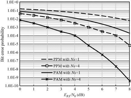
Figure 5.23 compares the bit error probability versus ![]() for a binary PPM signal with different
for a binary PPM signal with different ![]() values. We can observe that the bit error probability significantly decreases when increasing the redundancy of the code repetition coder.
values. We can observe that the bit error probability significantly decreases when increasing the redundancy of the code repetition coder.
Figure 5.23 Bit error probability versus ERX/N0 for PPM-TH-UWB and PAM-DS-UWB signals with one pulse per bit (Ns = 1) and four pulses per bit (Ns = 4)
The average symbol error probability for M-ary PPM can be written as follows
(5.36) 
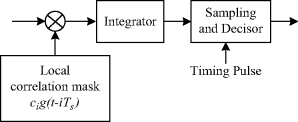
The optimum demodulation for PAM-DS-UWB is similar to that for PPM-TH-UWB. As shown in Figure 5.24, the difference lies in the local correlation mask which is here the DS pulse template ![]() .
.
Figure 5.24 Optimum demodulation for a PAM-DS-UWB signal
For the binary orthogonal PAM signal, the minimal bit error probability can be expressed as follows
Comparing Equations 5.37 and 5.35, it can be seen that binary orthogonal PPM signals require a factor of two in energy to achieve the same error probability as binary antipodal PAM signals. Consequently, the bit error probability of binary orthogonal signals is 3 dB worse than for binary antipodal signals. It can be observed from the error probability in Figure 5.23 that at any given error probability, the SNR required for PPM is 3 dB more than that for PAM.
The average symbol error probability for M-ary PAM can be written as follows
(5.38) 
where Es is the energy per symbol.
5.3.4 Noncoherent Detection for IR-UWB
The optimum demodulator may be quite complex in order to induce an appropriate template signal in the receiver especially in a multipath channel. The hardware itself may also consume a lot of power. Noncoherent energy detection is a suboptimal demodulation scheme. It is possible to capture the multipath energy easily, since the multipath combining does not require any knowledge with respect to the phases or polarities. Although this advantage can only be obtained at the expense of a higher SNR, the envelope detection is a useful alternative especially for low power, low complexity and low data rate systems.
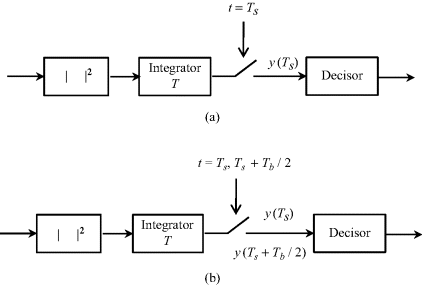
The noncoherent energy detection can be used for IR-UWB with OOK or PPM. Figure 5.25 shows the block diagram of the energy detector for OOK and PPM. The detector consists of a squarer circuit, an integrator with integration time T and a decisor. The received signal is first squared and then integrated over time T. Here we assume one pulse for one bit and the integration time T is large enough to collect the transmitted energy over one bit for ease of explanation. In the OOK scheme, since the energy detector output y(Ts) for bit “1” should be larger than that for bit “0,” we can assume a threshold to decide the transmitted bit to be “1” or “0” in the decisor. On the other hand, in the PPM scheme, the energy detector outputs the sampling values at both the first and last half of one bit duration. If the value y(Ts) in the first half is larger than y(Ts + Tb/2) in the last half, the pulse signal should be transmitted at the first position, otherwise the pulse signal is transmitted Tb/2 s later where Tb is the bit duration. Based on this information the decision circuit can also decide the transmitted bit to be “1” or “0.”
Figure 5.25 Block diagram of energy detector for IR-UWB with (a) OOK and (b) PPM
To derive the error probability of energy detection for IR-UWB, we have to know the noise PDF at first. However, due to the square behavior of the energy detector, the noise PDF is obviously not Gaussian at the detector outputs. Assuming a wide communication bandwidth B, we may consider the integrator output as the sum of 2M = 2BT + 1 independent random variables. Hence, the resulting decision variable y is a sum of 2M independent variables with chi-square distribution. According to the central limit theorem, the PDF of y tends to be a Gaussian function when 2M tends to infinity. In general, when 2M becomes higher than 40, the density of probability of y becomes Gaussian with a confidence better than 5%. In other words, as long as the product of bandwidth B and integration time T is larger than 20, the Gaussian approximation is valid. This condition is basically satisfied in body area UWB communications, because the data rate is usually below 10 Mbps and the bandwidth is at least 500 MHz.
Now let us assume that the information bits are equally probable and the mean energy of the transmitted signals is ![]() over one bit. Then for OOK, the signal for bit “1” will have energy of 2
over one bit. Then for OOK, the signal for bit “1” will have energy of 2![]() , whereas for bit “0” no energy is transmitted. Under the Gaussian approximation for the noise at the output of the energy detector, the bit error probability of OOK can be simply expressed as (Dubouloz et al., 2005)
, whereas for bit “0” no energy is transmitted. Under the Gaussian approximation for the noise at the output of the energy detector, the bit error probability of OOK can be simply expressed as (Dubouloz et al., 2005)
(5.39) 
It should be noted that the optimal threshold in the OOK decisor depends on the SNR level, and the above bit error probability is given at the optimal threshold. For a fixed threshold in actual implementation, 0.6 times of 2![]() may be a reasonable choice, and the corresponding bit error probability will degrade compared with that in optimal threshold.
may be a reasonable choice, and the corresponding bit error probability will degrade compared with that in optimal threshold.
On the other hand, for PPM, no threshold setting is required because we only need to compare the magnitude of the integration value in the first half and the last half of a bit duration. The transmitted energy per bit is always ![]() for both “1” and “0.” Based on the same approximation, the bit error probability can be expressed as
for both “1” and “0.” Based on the same approximation, the bit error probability can be expressed as
(5.40) 
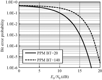
Figures 5.26 and 5.27 show the bit error probability versus Eb/N0 for OOK and PPM with noncoherent energy detection, respectively. The basic bit error probability is at a similar level for the two modulation schemes for the same Eb/N0. Due to the adoption of the optimum threshold, OOK seems to outperform PPM slightly. Moreover, an obvious degradation of error probability is observed, for both OOK and PPM, with the increase of the integration time T for a fixed bandwidth. This is attributed to the increased noise energy. In order to improve the bit error probability, it is therefore effective to collect all the signal energy at an integration time T as short as possible.
Figure 5.26 Bit error probability versus Eb/N0 for OOK energy detection
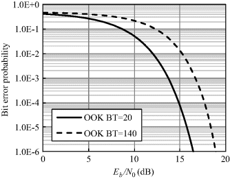
Figure 5.27 Bit error probability versus Eb/N0 for PPM energy detection
5.3.5 MB-OFDM Demodulation
As described in Section 5.2.3, OFDM modulation includes CP insertion and IFFT operation. Thus the OFDM demodulation mostly revolves around CP removal and FFT operation.
Figure 5.28 shows the corresponding OFDM receiver for the OFDM transmitter in Figure 5.11. The received signal is then quadrature-mixed down to baseband using cosine and sine waves at the carrier frequency. Since this process also creates signals at two times carrier, low-pass filters are used to reject the high frequency components. The baseband signals are then sampled using ADC, and a forward FFT is used to convert them back to the frequency domain. The FFT process returns ![]() parallel streams. These streams are respectively converted to a binary stream using an appropriate symbol detector and are then recombined into a serial stream, that is, the demodulated binary data.
parallel streams. These streams are respectively converted to a binary stream using an appropriate symbol detector and are then recombined into a serial stream, that is, the demodulated binary data.
Figure 5.28 Block diagram of an OFDM receiver

For the bit error probability of the MB-OFDM UWB signal, we can express the probability of error for each subcarrier for the case of OFDM with QAM modulation as follows
where ![]() is the constellation power, and
is the constellation power, and ![]() is the energy per symbol. When
is the energy per symbol. When ![]() and
and ![]() , Equation 5.41 is in fact the probability of error for OFDM with BPSK and QPSK modulation, respectively.
, Equation 5.41 is in fact the probability of error for OFDM with BPSK and QPSK modulation, respectively.
5.4 RAKE Reception
As shown in Chapter 4, various body postures and movements will result in a multipath propagation channel in body area. The multipath propagation channel makes electromagnetic waves traveling along the body reflected, diffracted, and scattered, so that a received signal ends up being the superimposition of several attenuated, delayed, and eventually distorted replicas of a transmitted waveform. This can result in either constructive or destructive interference, amplifying or attenuating the signal power at the receiver. This effect is called fading, and is referred to as multipath fading. Strong destructive interference may result in temporary failure of communication due to a severe drop in the channel SNR. In order to counter the effects of multipath fading, a RAKE receiver has been proposed (Price and Green, 1958). The RAKE receiver consists of multiple correlators, in which the received signal is multiplied by time-shifted versions of a locally generated code sequence. The intention is to separate signals such that each finger only sees signals coming in over a single path. The spreading code is chosen to have a very small autocorrelation value for any nonzero time offset. This avoids crosstalk between fingers.
The RAKE receiver is designed to optimally detect a spread spectrum signal transmitted over a multipath channel. It is essentially an extension of the concept of the MF in Section 5.3.1. In the MF receiver, the signal is correlated with a locally generated copy of the signal waveform. If, however, the received signal is distorted by the channel, the receiver should correlate the incoming received signal by a copy of the expected received signal, rather than by a copy of the transmitted waveform. Thus the receiver should estimate the delay profile of the channel, and adapt its locally generated copy according to this estimate. In Chapter 4, the body area UWB multipath channel model has been determined statistically based on the classical Saleh–Valenzuela model, which has a tapped-delay-line format. This enables the receiver to have the knowledge of the channel delay profile characteristics, including multipath delays, phases of the multipath components, amplitudes of the multipath components and number of multipath components.
There are two primary methods to combine the RAKE-receiver finger outputs. One method weights each output equally and is therefore called equal gain combining (EGC). The second method uses the data to estimate weights which maximize the SNR of the combined output. This technique is known as maximal ratio combining (MRC). As can be seen, with the EGC method, the different contributions are first aligned in time and then added without any particular weighting. In MRC, the different contributions are weighted before the combination and the weights are determined to maximize the SNR before the decision process.
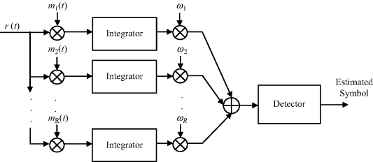
Figure 5.29 shows the structure of the RAKE receiver, which consists of a parallel bank of NR correlators, followed by a combiner that determines the variable to be used for the decision on the transmitted signal. Each correlator is locked on one of the different replicas of the transmitted signal. ![]() are the correlator masks which are the delayed replicas of the transmitted signal.
are the correlator masks which are the delayed replicas of the transmitted signal. ![]() are the statistically independent time-invariant weighting factors which depend on the combining method implemented at the receiver. In the case of EGC, all factors are equal to 1, that is, the combiner simply adds the outputs of the correlators without applying any weighting. In the MRC case, the output of each branch is multiplied by a weighting factor, which is proportional to the signal amplitude on that branch.
are the statistically independent time-invariant weighting factors which depend on the combining method implemented at the receiver. In the case of EGC, all factors are equal to 1, that is, the combiner simply adds the outputs of the correlators without applying any weighting. In the MRC case, the output of each branch is multiplied by a weighting factor, which is proportional to the signal amplitude on that branch.
Figure 5.29 RAKE receiver with NR parallel correlators
The RAKE receiver can take advantage of multipath to improve the SNR at the receiver, yet the adoption of a RAKE considerably increases the complexity of the receiver. This complexity increases with the number of multipath components analyzed and combined before decision, and can be reduced by decreasing the number of components processed by the receiver. However, a reduction of the number of paths leads to a decrease of energy collected by the receiver. A quasi-analytical investigation of the existing trade-off between receiver complexity and percentage of captured energy in a RAKE receiver for IR-UWB systems can be found in Win and Scholtz (1998).
As described in Chapter 4, the body area UWB multipath channel can be modeled by a tapped delay line with statistically independent time-invariant tap weights. Hence, a RAKE receiver can process the received signal in an optimum manner which will achieve the performance of an equivalent L-order diversity communication system.
In the multipath fading propagation channel, the instantaneous SNR is a random variable at the receiver output that includes the effect of fading. The variation of the SNR is a random process related to the fading characteristics. If the received SNR is no longer fixed, the bit error performance in optimum demodulation no longer applies. Therefore, we must average the bit error probability in the AWGN channel over the PDF of the SNR (Proakis, 2007). That is, we must evaluate the integral
where ![]() represents the average SNR,
represents the average SNR, ![]() is the average bit error probability in a multipath fading channel,
is the average bit error probability in a multipath fading channel, ![]() is conditional error probability in AWGN channel and
is conditional error probability in AWGN channel and ![]() denotes the PDF of
denotes the PDF of ![]() when the SNR is random. As we can see here, the term “average” in the error probability refers to statistical averaging over the probability distribution of the SNR. Therefore, we need to derive the probability distribution of the SNR under the RAKE reception in the body area multipath fading channel.
when the SNR is random. As we can see here, the term “average” in the error probability refers to statistical averaging over the probability distribution of the SNR. Therefore, we need to derive the probability distribution of the SNR under the RAKE reception in the body area multipath fading channel.
Assuming the signal power gain of the kth resolvable multipath
(5.43) ![]()
then we have the instantaneous SNR on the kth multipath channel ![]()
(5.44) ![]()
where Eb/N0 corresponds to the SNR per bit.
As described above, the RAKE receiver can process separately multiple received multipaths and achieve the SNR of an equivalent L-order diversity communication system. The received SNR per bit can then be represented as
(5.45) ![]()
in which L is the number of RAKE fingers and also the number of resolvable multipaths. Now we must determine the PDF of ![]() ,
, ![]() . The whole derivation process can be generalized into two steps.
. The whole derivation process can be generalized into two steps.
(5.46) ![]()
![]()
(5.48) ![]()
(5.49) ![]()
(5.50) 
(5.51) ![]()
(5.52) ![]()
(5.53) ![]()
(5.54) ![]()
(5.55) ![]()
(5.56) ![]()
(5.57) ![]()
(5.58) 
(5.59) 
(5.60) ![]()
5.5 Diversity Reception
Diversity is a technique for improving the communication performance by using two or more communication channels (or branches) with different characteristics. It is based on the consideration that multiple versions of the same signal may be received and combined in the receiver because the same information may reach the receiver on statistically independent channels. The simplest case is a receiver with two antennas. By setting the receiver to always choose the antenna which has larger instantaneous power, the SNR statistic at the detector input is changed so that it has a smaller probability of being low. Such a combining scheme is known as selection combining (SC) of diversity.
Diversity can exploit multipath propagation to result in a diversity gain for combating the multipath fading. It is most effective when the different transmission channels carry independent fading copies of the same signal. This means that the correlation between the fading of the channels is low. The correlation coefficient characterizes the correlation between received signals on different branches. Assuming x and y as the signal envelopes on two different branches, the correlation coefficient is given as
(5.61) 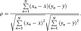
For two statistically independent receiver signals, the correlation coefficient is zero, which gives the best diversity effectiveness. In general, when the correlation coefficient is below a certain threshold, typically 0.5 or 07, the receiver signals are considered as decorrelated. This requirement is met in most body area communication scenarios, and a diversity effect is thus expected to provide an effective improvement on the bit error probability performance.
The promising diversity schemes in body area communications are spatial diversity and polarization diversity. Both spatial diversity and polarization diversity generally employ multiple receiving antennas. In spatial diversity, the antennas are separately placed on the human body to receive signals over different propagation paths. In polarization diversity, the antennas are arranged with different polarization such as vertical polarization and horizontal polarization to receive different signals. Since both schemes provide an acceptable correlation coefficient below 0.5 (Shi and Wang, 2010), a diversity combining technique is applicable on the receiver to obtain a diversity gain.
The diversity combining techniques can be distinguished into three kinds.
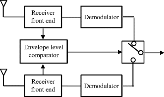
The first kind is SC diversity. Of the M received signals, the signal with the maximum instantaneous SNR is selected. The corresponding SNR is
(5.62) ![]()
where ![]() is the SNR at the mth branch. In reality, the “instantaneous SNR” is an average SNR over a time period which is longer than the reciprocal of the signal bandwidth. Figure 5.30 shows the block diagram of SC diversity. The envelope levels are actually used to measure the sum of signal and noise for selecting the branch.
is the SNR at the mth branch. In reality, the “instantaneous SNR” is an average SNR over a time period which is longer than the reciprocal of the signal bandwidth. Figure 5.30 shows the block diagram of SC diversity. The envelope levels are actually used to measure the sum of signal and noise for selecting the branch.
Figure 5.30 Block diagram of SC diversity
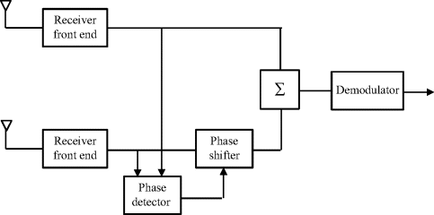
The second kind is EGC diversity in which all the received signals are summed coherently. Figure 5.31 shows the block diagram of EGC diversity with two diversity branches. Each branch corresponds to a single fading channel. Defining the received signal at the mth diversity branch as ![]() (m = 1, 2, . . ., M), the summed signal is then given by
(m = 1, 2, . . ., M), the summed signal is then given by
Figure 5.31 Block diagram of EGC diversity
(5.63) ![]()
Under the decorrelated condition, the received fading signal ![]() is approximately considered as independent. The EGC diversity equally weighs each branch and sums them to produce the decision statistic. That is
is approximately considered as independent. The EGC diversity equally weighs each branch and sums them to produce the decision statistic. That is
where ![]() denotes the diversity weight of the mth branch, which is set to
denotes the diversity weight of the mth branch, which is set to ![]() , that is, the amplitudes are set to one and the phases are adjusted to the same for all branches. Then we have the combined signal as
, that is, the amplitudes are set to one and the phases are adjusted to the same for all branches. Then we have the combined signal as
(5.65) ![]()
On the other hand, the signal will be perturbed by AWGN at each branch. Assuming the AWGN is statistically independent and has the same noise power N, the mean SNR at the output of the EGC diversity receiver will be given by
because ![]() .
.
Since EGC diversity does not require the amplitude information of the received signals, in other words, it only needs the phase information to make the outputs of the different diversity branches be co-phased before being summed, it is advantageous in terms of the simple implementation and better performance compared with the SC diversity.
The third kind of combining technique of diversity is MRC diversity. Figure 5.32 shows the block diagram for MRC diversity. The received signals are not only phase-corrected but also weighted by the amplitude. The weighting factor for the amplitude is proportional to
Figure 5.32 Block diagram of MRC diversity
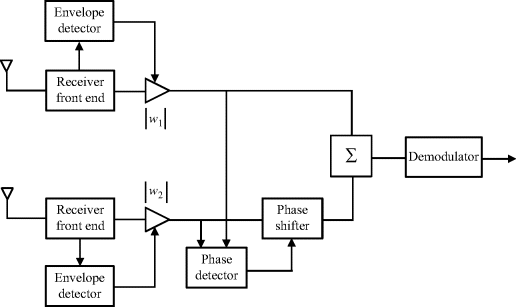

in the mth branch so that
(5.67) 
Then from Equation 5.64 the combined receive signal in MRC diversity is
(5.68) 
and the combined noise power is
(5.69) ![]()
So the mean SNR for the MRC diversity is given by
The MRC diversity obviously performs better than EGC. However, it suffers from the necessity of detecting the signal envelopes in all branches, which yields a significant increase in receiver complexity.
The CDF is a useful index to demonstrate the diversity effect. Since the received signals vary according to the log-normal distribution in body area communications, the combined signal also approximately follows the log-normal distribution as described in the previous section. We plot the CDF for single branch, two-branch EGC and two-branch MRC as a function of normalized received signal level in Figure 5.33 as an example in the log-normal fading environment. We assume the received signal levels to be v1 and v2 in two log-normal channels; the equivalent received signal level for EGC diversity and MRC diversity are equal to ![]() and
and ![]() , respectively, based on Equations 5.66 and 5.70. At 1% CDF value, for example, both the EGC and MRC improve the signal level by nearly 10 dB. However, the noise power in EGC diversity is twice that in MRC diversity. This means MRC has superior performance to EGC.
, respectively, based on Equations 5.66 and 5.70. At 1% CDF value, for example, both the EGC and MRC improve the signal level by nearly 10 dB. However, the noise power in EGC diversity is twice that in MRC diversity. This means MRC has superior performance to EGC.
Figure 5.33 CDF of diversity in log-normal environment

Assuming the average SNR at each branch is the same, the average bit error probability for EGC diversity and MRC diversity are given, respectively, by
(5.71) ![]()
and
(5.72) ![]()
where ![]() or
or ![]() is the average SNR at each branch,
is the average SNR at each branch, ![]() or
or ![]() is the bit error probability in AWGN channel, and
is the bit error probability in AWGN channel, and ![]() or
or ![]() is the PDF on
is the PDF on ![]() or
or ![]() when
when ![]() or
or ![]() is given. The PDFs can be derived by using the MGF method as described in the previous section.
is given. The PDFs can be derived by using the MGF method as described in the previous section.
A spatial diversity reception is especially useful in in-body communication for improving the shadow fading, as shown in the next chapter.
Abramowitz, M. and Stegun, I. (1972) Handbook of Mathematical Functions with Formulas, Graphs, and Mathematical Tables, 9th edn, Dover, Washington, DC.
Arthurs, E. and Dym, H. (1962) On the optimum detection of digital signals in the presence of while Gaussian noise – A geometric interpretation and a study of three basic data transmission systems. IRE Transactions on Communications Systems, 10 (4), 336–372.
Benedetto, D.M.-G. and Giancola, G. (2004) Understanding Ultra Wide Band Radio Fundamentals, Prentice Hall, New Jersey.
Dubouloz, S., Denis, B., de Rivaz, S., and Ouvry, L. (2005) Performance analysis of LDR UWB non-coherent receivers in multipath environments. Proceedings of IEEE International Conference on Ultra-Wideband, pp. 491–496.
Dufresne, D. (2009) Sums of Lognormals, Centre for Actuarial Studies, University of Melbourne, Melbourne.
ECMA (2005) Standard ECMA-368: High data rate ultra wideband PHY and MAC standard, December 2005 [Online]. http://www.ecma-international.org/publications/files/ECMA-ST/ECMA-368.pdf.
FCC (2002) Revision of Part 15 of the Commission's rules regarding ultra-wideband transmission system: first report and order, Technical Report FCC 02-48 (Adopted February 14, 2002; Released April 22, 2002).
Haykin, S. (1988) Digital Communications, John Wiley & Sons, Ltd, New York.
IEEE P802.15 (2004) Multi-band OFDM physical layer proposal for IEEE 802.15 Task Group 3a (Doc. Number P802.15-03/268r3).
Lindsey, W.C. and Simon, M.K. (1973) Telecommunications Systems Engineering, Prentice Hall, New Jersey.
Price, R. and Green, P.E. Jr (1958) A communication technique for multipath channels. Proceedings of IRE, 46, 555–570.
Proakis, J.G. (2007) Digital Communications, 4th edn, McGraw-Hill, Boston.
Shi, J. and Wang, J. (2010) Channel characterization and diversity feasibility for in-body to on-body communication using low-band UWB signals. Proceedings of the 3rd International Symposium on Applied Science in Biomedical and Communication Techniques, Rome, Italy.
Smith, D.R. (1985) Digital Transmission Systems, Van Nostrand Reinhold, New York.
Win, M.Z. and Scholtz, R.A. (1998) On the energy capture of ultrawide bandwidth signals in dense multipath environments. IEEE Communications Letters, 2 (9), 245–247.
Wu, J., Mehta, N., and Zhang, J. (2005) A flexible lognormal sum approximation. Proceedings of IEEE Global Telecommunications Conference, pp. 3413–3417.
