Chapter 3
Electromagnetic Analysis Methods
The difficulty in measurement of an actual human body, especially inside a human body, means that numerical electromagnetic analysis methods play an important role in body area communications. Numerical electromagnetic analysis methods are especially helpful to clarify propagation characteristics and establish channel models in or on the body area. Rapid progress with computers has enabled high-level numerical simulation with the aid of high-resolution human body models. In this chapter, we will introduce three representative numerical methods for electromagnetic analysis: the finite-difference time-domain (FDTD) method; the finite element method (FEM); and a hybrid method combining the method of moments (MoM) and the FDTD method. After introducing the basis and algorithm for the numerical methods, human body models for use in numerical analysis will also be described.
3.1 Finite-Difference Time-Domain Method
3.1.1 Formulation
The FDTD method (Taflove and Hagness, 2000) is currently the most widely accepted numerical electromagnetic analysis method for human bodies.
The FDTD formulations are derived from the following Maxwell time-domain equations
where ![]() is the electric field,
is the electric field, ![]() is the magnetic field,
is the magnetic field, ![]() is the permittivity,
is the permittivity, ![]() is the permeability and
is the permeability and ![]() is the conductivity. To derive the algorithm, we rewrite Equation 3.1 as
is the conductivity. To derive the algorithm, we rewrite Equation 3.1 as
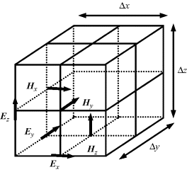
The FDTD discretization for the above equations is based on a Yee cell approach as shown in Figure 3.1. A special feature of the Yee cell is that the electric field E and magnetic field H components are staggered one half space cell apart. That is to say, the E field is generally assigned at the edges of the Yee cell, and the H field is assigned on the faces of the Yee cell, which facilitates the differencing scheme. If we denote the field F (E or H) at spatial location ![]() and time step
and time step ![]() by
by
Figure 3.1 Yee cell in FDTD algorithm
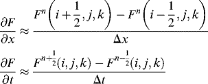
(3.3) ![]()
using the central difference approximations such as
we can discretize Equation 3.2 and consequently derive the electric and magnetic field components. In the Yee cell notation, the electric field E is assigned at t = (n − 1)Δt, nΔt, (n + 1)Δt, and the magnetic field H is assigned at (n − 1/2)Δt, (n + 1/2)Δt. Then the time differentiation in Equation 3.2 for E must be conducted at t = (n − 1/2)Δt, and the time differentiation in Equation 3.4 for H must be conducted at t = nΔt. According to the notation in Equation 3.4, Equation 3.2 can be written as
(3.5) 
where
(3.6) ![]()
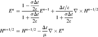
Thus we have
That is to say, from the electric field En−1 at t = (n − 1)Δt and the magnetic field Hn−1/2 at t = (n − 1/2)Δt, we can get En at t = nΔt. And from the magnetic field Hn−1/2 at t = (n − 1/2)Δt and the electric field En at t = nΔt, we can get Hn+1/2 at t = (n + 1/2)Δt.
In the Cartesian coordinates, Equation 3.2 can be written as
(3.8a) ![]()
(3.8b) ![]()
(3.8c) ![]()
(3.8d) ![]()
(3.8e) ![]()
(3.8f) ![]()
Its z components, for example, are as follows according to Equation 3.7:
(3.9) 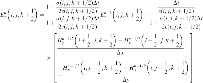
(3.10) 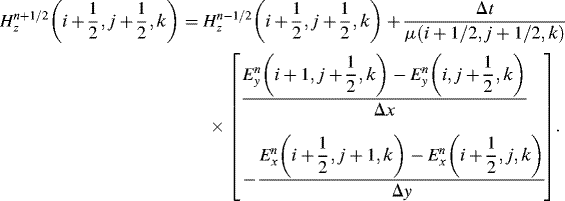
Its x and y components are also in the same form. For applying the FDTD method to human bodies, the Yee cells correspond completely to the cells in human body models. By assigning each cell a corresponding permittivity and a conductivity, we can easily model the anatomical tissues and organs, and calculate the interior electric and magnetic fields.
A noticeable problem in the assignment of permittivity and conductivity is that, referring to Figure 3.1 and Equation 3.7, the permittivity and conductivity are required at the edges of the cell. In other words, the permittivity and conductivity are required at the boundary of different tissues, because each cell is identified rigorously as belonging to one type of tissue in numerical human body models.
Let us consider the permittivity and conductivity at the boundary of four cells as shown in Figure 3.2. According to Ampere's law, along the closed curve C (denoted by dotted lines) with an area of S (S=S1+S2+S3+S4), we have
Figure 3.2 View of the x-y plane of four cells with different permittivities and conductivities
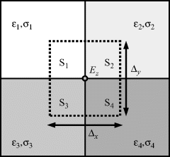
(3.11) 
which means the average permittivity and conductivity of the four neighboring cells should be used at the boundary.
3.1.2 Absorbing Boundary Conditions
The FDTD method requires discretization of the entire spatial domain over which the solution is to be calculated. However, it is impossible to discretize an infinite space, because of the finite memory capability of computers. The calculation domain, therefore, must be truncated to a finite size, even for an open-region problem. Once the infinite space of the open-region problem is truncated to a finite size, absorbing boundary conditions must be applied to the outside boundaries of the calculation domain in order to simulate the nonreflective nature of open space.
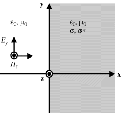
One of the most popular and effective absorbing boundary conditions is known as the perfectly matched layer (PML) (Berenger, 1994). The basic concept of PML is based on impedance matching to minimize reflections. For a plane wave traveling normal to a PML medium as shown in Figure 3.3, the characteristic impedances in the free space and in the PML medium are
Figure 3.3 A plane wave traveling normal to a PML medium
(3.12) ![]()
and
(3.13) 
respectively. Here ![]() is called the magnetic conductivity. From the impedance matching condition, that is, Z = Z0, we have
is called the magnetic conductivity. From the impedance matching condition, that is, Z = Z0, we have
That is to say, the reflection from the PML medium is zero for a normal incidence as long as Equation 3.14 is satisfied.
For incidence with an angle, however, zero reflection at the PML plane is also required. To do this, we first split each electric field and magnetic field component into two nonphysical subcomponents, respectively, that is,
(3.15) 
(3.16) 
where the second subscripts represent the traveling direction of the wave. In each traveling direction, we then assign a respective electric and magnetic conductivity ![]() to characterize the PML medium. In such a way, Maxwell's equations in the PML medium become 12 equations in the Cartesian coordinates:
to characterize the PML medium. In such a way, Maxwell's equations in the PML medium become 12 equations in the Cartesian coordinates:
(3.17b) 
(3.17c) 
(3.17d) 
(3.17e) 
Based on Equation 3.14, the matching conditions for PML are as follows.
At the PML planes normal to the x axis:
(3.18) 
At the PML planes normal to the y axis:
(3.19) 
At the PML planes normal to the z axis:
(3.20) 
To incorporate PML into the FDTD procedure, the same discretization with the Yee cell algorithm for Equation 3.17a is necessary. For example, the discretization for Exy in Equation 3.17a is
(3.21) 
and the discretization for Hzx in Equation 3.17f is
(3.22) 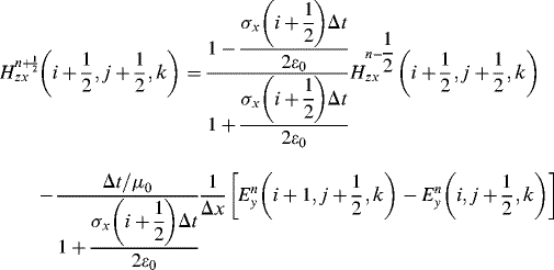
where ![]() changes only along the x direction, and
changes only along the x direction, and ![]() changes only along the y direction.
changes only along the y direction.
Theoretically speaking, the PML provides a perfect absorption for traveling waves with any angle of incidence. However, in practice, the PML must be terminated, because of finite computer memory. Typically termination is accomplished using a perfect electric conductor, which introduces a reflection back into the calculation domain. The performance of PML is therefore characterized by three parameters: (a) thickness; (b) conductivity profile; and (c) the reflection coefficient at normal incidence.
Let us consider an L layer PML parallel to the w (w = x, y or z) plane for an incidence with angle ϕ, as shown in Figure 3.4. The impedance matching condition should be satisfied in all layers, that is, Z0 = Z1 = . . .= ZL, or
(3.23) ![]()
Figure 3.4 L layer PML for incidence with angle ϕ
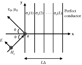
If we choose
(3.24) 
where Δ = Δx, Δy, or Δz, and N is the maximum cell number in the x, y or z direction, the reflection coefficient can be expressed as
(3.25) ![]()
Hence the required reflection coefficient is determined by the layer number L, the conductivity profile parameter M and σmax. In general, M = 2 ~ 4, L = 4 ~ 16, and σmax is determined by the required reflection coefficient at ϕ = 0, that is,
(3.26) ![]()
A typical choice for R(0) may be −120 dB.
3.1.3 Field Excitation
In the FDTD calculation, an energy source must be coupled into the algorithm to excite the electric and magnetic fields. Typical energy sources in body area communications are transmitting antennas. For a transmitting antenna, a voltage source v(t) is commonly applied at the feeding gap of the antenna and then is converted into the electric field via ![]() , where
, where ![]() is the cell size. The feeding current can be calculated as
is the cell size. The feeding current can be calculated as ![]() by integrating the magnetic field along a closed curve C according to Ampere's law. Then the input impedance Zin(ω) of the antenna can be obtained by
by integrating the magnetic field along a closed curve C according to Ampere's law. Then the input impedance Zin(ω) of the antenna can be obtained by
(3.27) ![]()
where the notation ![]() indicates Fourier transform.
indicates Fourier transform.
For the voltage source v(t), it may be a sinusoidal voltage with an angular frequency ω. It can also be a pulse voltage which is efficient to derive wide band characteristics. A Gaussian pulse is a typical excitation source in FDTD simulation in view of its smooth frequency spectrum and ease of formulation. The Gaussian pulse is expressed as
(3.28) ![]()
where the coefficient σt is often set to be ![]() . Figure 3.5 shows its time waveform and frequency spectrum. The frequency spectrum contains a direct current (DC) component. If we do not need the DC component, we can use a derivative Gaussian pulse as the voltage source. A general expression of the derivative Gaussian pulse is
. Figure 3.5 shows its time waveform and frequency spectrum. The frequency spectrum contains a direct current (DC) component. If we do not need the DC component, we can use a derivative Gaussian pulse as the voltage source. A general expression of the derivative Gaussian pulse is
Figure 3.5 (a) Time domain Gaussian pulse waveform and (b) its frequency spectrum

(3.29) ![]()
where n denotes the nth derivative.
3.1.4 FDTD Flow Chart and Code
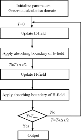
Figure 3.6 shows a flow chart of FDTD calculation. First, the initialization for various field components and setting for various parameters of the analysis target are performed. In the ‘Update E-field’ subroutine, En−1 and Hn−1/2 are the inputs and En is calculated as the output. In the ‘Apply absorbing boundary of E-field’ subroutine, En at the boundary is determined from En and En−1 inside the boundary based on the PML principle. Similarly, in the ‘Update H-field’ subroutine, En and Hn−1/2 are the inputs and Hn+1/2 is calculated as the output. In the ‘Applying absorbing boundary of H-field’ subroutine, Hn+1/2 at the boundary is determined from Hn+1/2 and Hn−1/2 inside the boundary based on the PML principle. This process is repeated until the exciting voltage signal travels through the entire analysis domain and reaches a steady state.
Figure 3.6 Flow chart of the FDTD method
Two FDTD codes in Fortran are available to download from the website www.wiley.com/go/wang/bodyarea. The first one is tuned for a vector processor computer. The scenario is a short dipole excited with a Gaussian pulse in free space. The outputs are feeding voltage and current on the short dipole and electric and magnetic fields at some observation points.
The second one is written for use in parallel personal computers with a message passing interface (MPI) library (Wang et al., 2004). The entire FDTD calculation domain is divided into eight subspaces, as shown in Figure 3.7. Each subspace is handled by one CPU, and all the CPUs execute the same program. To calculate the field in the boundary cells, we need to know the field in the cells belonging to the neighboring subspaces. This is realized by using the MPI library to transfer the data from one CPU to another CPU. For simplicity, let us consider a one-dimensional case as shown in Figure 3.8. We divide the whole FDTD space into two subspaces: in this case, S0 and S1. S0 and S1 are handled by CPU0 and CPU1, respectively. In the E-field calculation, we pass HM in subspace S0 to S1, which is used as H0 for obtaining E1 in S1. In the H-field calculation, we pass E1 in subspace S1 to S0, which is used as EM+1 for obtaining HM in subspace S0. It is straightforward to extend this algorithm to a three-dimensional case to obtain a practical parallel FDTD code. Data transfer among the CPUs can be conducted using a gigabit network interface.
Figure 3.7 Division of FDTD space into eight subspaces. Each subspace is handled by one CPU
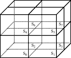
Figure 3.8 One-dimensional illustration of the MPI-based data communication between the subspaces used in the parallel FDTD code. (a) HM in S0 is passed to H0 in S1 for calculating E1 in S1. (b) E1 in S1 is passed to EM+1 in S0 for calculating HM in S0 (Wang et al., 2004). Reproduced with permission from Wang J., Fujiwara O., Watanabe S. and Yamanaka Y., “Computation with a parallel FDTD system of human-body effect on electromagnetic absorption for portable telephones,” IEEE Transactions on Microwave Theory and Techniques, 52, 1, 966–971, 2004. © 2004 IEEE
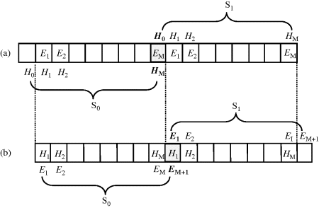
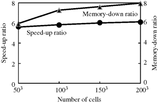
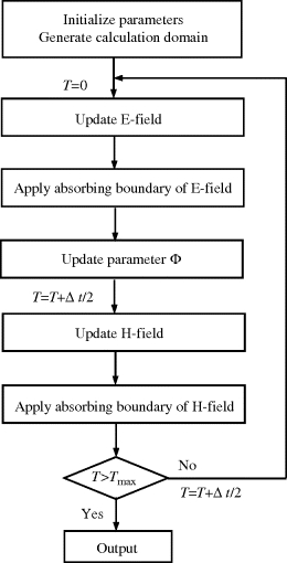
Figure 3.9 shows the flow chart of the MPI-based parallel FDTD code. The MPI communication subroutines are added after applying absorbing boundary conditions for the electric field and magnetic field, respectively. A performance evaluation for the parallel code is given in Figure 3.10 for eight CPUs. The abscissa indicates the number of cells of the entire FDTD domain, and the left and right ordinates indicate the speed-up ratio and memory-down ratio, respectively. The speed-up ratio is defined as the ratio of the run time in one CPU case to that in eight CPUs, and the memory-down ratio is defined as the ratio of the memory required in each CPU when the calculation is conducted in one CPU to that in eight CPUs. For both the speed-up and memory-down ratios, the ideal value is eight because eight CPUs are used. As can be seen, the code exhibits an almost fixed speed-up ratio of six, which corresponds to a reasonable efficiency of 75%, and a memory-down ratio of approximately eight, which means that the overhead for the memory in the parallel code is almost negligible.
Figure 3.9 Flow chart of MPI-based parallel FDTD method

Figure 3.10 Performance of the parallel FDTD code (Wang et al., 2004). Reproduced with permission from Wang J., Fujiwara O., Watanabe S. and Yamanaka Y., “Computation with a parallel FDTD system of human-body effect on electromagnetic absorption for portable telephones,” IEEE Transactions on Microwave Theory and Techniques, 52, 1, 966–971, 2004. © 2004 IEEE
3.1.5 Frequency-Dependent FDTD Method
A pulse with a wide frequency band is often used as an excitation in the FDTD method, especially for getting wide band propagation characteristics. As described in the previous chapter, the permittivity and conductivity of biological tissue are frequency-dependent. A useful expression for the frequency-dependent tissue properties is known as the Debye approximation as shown in Section 2.3. With this approximation, it is possible to incorporate the frequency-dependent tissue properties into the FDTD method.
The Debye approximation for complex permittivity of biological tissue is expressed as
where ![]() is the relative permittivity at infinite frequency,
is the relative permittivity at infinite frequency, ![]() is the frequency domain susceptibility, and σ0 is the ionic conductivity at zero frequency. We can relate the first and second terms in Equation 3.30 to the electric flux density D(ω) and the third term to the current density J0(ω) because only the former two terms are due to the frequency dispersion of tissue. We then have
is the frequency domain susceptibility, and σ0 is the ionic conductivity at zero frequency. We can relate the first and second terms in Equation 3.30 to the electric flux density D(ω) and the third term to the current density J0(ω) because only the former two terms are due to the frequency dispersion of tissue. We then have
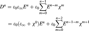
Since Maxwell's equations are to be solved iteratively in the time domain by using the FDTD method, we need to transfer Equations 3.31 and 3.32 into the time domain expressions. This can be realized by inverse Fourier transform. We thus have
where the asterisk denotes the convolution. With the electric flux density D(t), one of the Maxwell equations in Equation 3.1 can be expressed as
To incorporate Equations 3.33 and 3.34 into (3.35) for deriving a frequency-dependent FDTD formulation, we first discretize the time expression of Equation 3.33 at t = nΔt and t = (n − 1)Δt. Then we have
and consequently
Substituting Equations 3.36 and 3.37 into Equation 3.38 we obtain the update equation for electric field E as
(3.39) 
where
and
The time-domain susceptibility ![]() depends on the order of the Debye approximation. For the first-order Debye expression
depends on the order of the Debye approximation. For the first-order Debye expression
(3.42) ![]()
we have
(3.43) ![]()
where εs is the static permittivity at zero frequency, and τ is the relaxation time constant. Having found ![]() and using the definition in Equation 3.41, we can obtain
and using the definition in Equation 3.41, we can obtain
(3.44) ![]()
and
(3.45) ![]()
Substituting the above two equations into Equation 3.40 yields a simple update equation for ![]() as
as
(3.46) ![]()
With this update equation, the frequency-dependent permittivity and conductivity are well incorporated into the FDTD algorithm. Applying this approach to high-order Debye approximations is straightforward. Figure 3.11 shows the flow chart of the frequency-dependent FDTD method. This method is especially effective for a pulse excitation to obtain a wide band propagation characteristic over the human body.
Figure 3.11 Flow chart of frequency-dependent FDTD method
3.2 MoM-FDTD Hybrid Method
The MoM is another popular method to solve electromagnetic problems, especially electromagnetic scattering problems. When electromagnetic waves are incident on a conducting body, it produces currents in the body surface. These currents radiate and produce the scattered field. Such a scattering problem is governed by Green's functions. Based on the Green's functions in the frequency domain, MoM constructs electric field or magnetic field integral equations for the currents which are on the surface of the conducting body. By modeling the surface with a number of small meshes and assigning a surface current distribution at each edge of the meshes, MoM reduces the Green's-function-governed operator equations to a system of linear equations which is written in a matrix form. By solving the system of linear equations, the surface current at each mesh is determined, and from all these surface currents the scattering field can be calculated.
An obvious advantage of MoM is its high accuracy in modeling a complicated surface structure. This feature is especially effective in solving the electromagnetic problems with small-size and high-precision antennas. However, MoM is usually limited to homogeneous media because it requires calculating only boundary values on the surface, rather than values throughout the body. This yields a considerable restriction on its application to in-body communication where we need to know the received field signal inside the human body.
In this section, we introduce a hybrid technique which combines the MoM and FDTD method for analyzing body area propagations. The former is used to model the transmitting antenna outside a human body to calculate the scattered electric field from the antenna in the entire analysis region in the absence of the human body. By considering such an electric field as an incident field to the human body, the total field in or on the human body can be then calculated using a scattered field FDTD algorithm because the FDTD method is suited to model the human body's detailed anatomy. Such a hybrid technique combines the advantages of both the MoM and FDTD methods.
3.2.1 MoM Formulation
The boundary condition on a perfectly electric conductor (PEC) states that tangential electric fields on the surface must be zero, that is,
where n is the normal direction vector pointing outwardly, ![]() is the incident electric field,
is the incident electric field, ![]() is the scattered electric field which can be expressed in terms of the spatial convolution of electric current density J and the free-space Green's function in the frequency domain as
is the scattered electric field which can be expressed in terms of the spatial convolution of electric current density J and the free-space Green's function in the frequency domain as
where ![]() is the wavenumber,
is the wavenumber, ![]() is the intrinsic impedance of free space, and
is the intrinsic impedance of free space, and
(3.49) ![]()
represents the free-space Green's function. By substituting Equation 3.48 into 3.47, the electric field integral equation (EFIE) for PEC is obtained as follows
For a transmitting antenna, it can be considered as a PEC. In the MoM, the PEC surface is usually modeled either as a wire mesh – the so-called wire-grid model – or as a surface partitioned into smooth or piecewise-smooth patches – the so-called surface patch model. The wire-grid model makes all numerical integrals in the moment matrix one dimensional, and has been successfully applied in solving far-field radiation problems in particular. However, this approach is not well suited for calculating near-field and surface currents because of some existing problems such as the presence of fictitious loop currents in the solution, and difficulties in interpreting calculated wire currents and relating them to equivalent surface currents. Surface patch models can overcome these difficulties. For modeling arbitrarily shaped surfaces, planar triangular patch models are particularly appropriate. For example, triangular patches are capable of accurately conforming to any geometrical surface or boundary, the patch scheme is easily specified for computer input, and a varying patch density can be used according to the resolution required in the surface geometry or current.
With the triangular patch modeling, the current distribution at each edge of the patches can be represented by using the sum of basis functions as
where N is the total number of edges, an is an unknown coefficient and ![]() is a basis function associated with the nth edge to approximately represent the surface current. Figure 3.12 shows two triangles,
is a basis function associated with the nth edge to approximately represent the surface current. Figure 3.12 shows two triangles, ![]() and
and ![]() , corresponding to the nth edge of a triangulated surface (Rao, Wilton, and Glisson, 1982). Points in
, corresponding to the nth edge of a triangulated surface (Rao, Wilton, and Glisson, 1982). Points in ![]() can be designated by the position vector
can be designated by the position vector ![]() defined with respect to the free vertex of
defined with respect to the free vertex of ![]() . Similar remarks apply to the position vector
. Similar remarks apply to the position vector ![]() except that it is directed toward the free vertex of
except that it is directed toward the free vertex of ![]() . The plus or minus designation of the triangles is determined by the choice of a positive current reference direction for the nth edge, the reference for which is assumed to be from
. The plus or minus designation of the triangles is determined by the choice of a positive current reference direction for the nth edge, the reference for which is assumed to be from ![]() to
to ![]() . Referring to Figure 3.12, the basis function associated with the nth edge can be defined as
. Referring to Figure 3.12, the basis function associated with the nth edge can be defined as
Figure 3.12 Two triangles and geometrical parameters associated with an edge in the triangular patch modeling

(3.52) 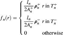
where ![]() is the length of the edge and
is the length of the edge and ![]() is the area of triangle
is the area of triangle ![]() .
.
By substituting Equation 3.51 into (3.50) and testing the EFIE with the curl of the basis functions, that is, ![]() , the matrix equation for the EFIE is finally expressed as
, the matrix equation for the EFIE is finally expressed as
(3.54) 
The matrix Equation 3.53 can be solved using a direct solution of the linear system, typically via LU decomposition, or by making use of an iterative algorithm of linear system solutions. Once the currents are obtained, the induced electromagnetic field can be calculated in the post-processing.
3.2.2 Scattered Field FDTD Formulation
Total electromagnetic fields are the sum of the incident and scattered fields, that is,
where E, Ei and Es are the total, incident and scattered electric fields, respectively, and H, Hi and Hs represent their magnetic counterparts. All quantities in Equations 3.56 and 3.57 are functions of both time and space. Maxwell's equations in the form of separate fields are generally expressed as
Since the human body is a lossy dielectric medium with electrical properties ε, σ and μ0, Equation 3.58 reduces to
Thus, there is no need to obtain information on the incident magnetic field. As long as we know the incident electric field, for example, by using the MoM as described in Section 3.2.1, we can calculate the scattered field due to the human body and then the total field from Equations 3.59 and 3.60.
After some manipulation of discretization for Equations 3.59 and 3.60, the scattered field FDTD formulation is derived straightforwardly as follows
(3.62) ![]()
where Δt is the time step, and n is the temporal step index.
3.2.3 Hybridization of MoM and FDTD Method
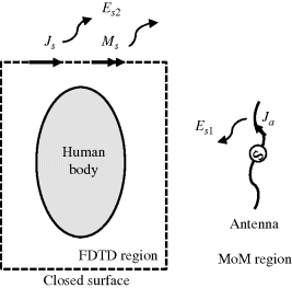
The concept of the hybrid MoM-FDTD method is depicted in Figure 3.13. There are two analysis regions: one is the MoM region including the transmitting antenna structure, and the other is the FDTD region including the human body to be irradiated by the electromagnetic field from the antenna. Ja denotes the electric current density on the antenna. Js and Ms denote the electric and magnetic current densities on a closed surface surrounding the human body, respectively. The closed surface can be chosen arbitrarily as long as it totally encompasses the human body. The following describes the calculation procedure of the hybrid MoM-FDTD method (Chakarothai et al., 2012).
Figure 3.13 Concept of hybrid MoM-FDTD method
(3.63) ![]()
(3.64) ![]()
(3.65) ![]()
(3.66) ![]()
(3.67) ![]()
(3.68) ![]()
(3.69) ![]()
(3.71) ![]()
3.3 Finite Element Method
For a time-harmonic field, that is, the field quantities are harmonically oscillating functions with a single angular frequency ω, Maxwell's equations can be expressed in a simplified form with complex phasor notation as
To solve Equation 3.72, we may first convert the first-order differential equations involving both E and H field quantities into second-order differential equations involving only E or H field. We can then obtain the differential equation for E by eliminating H with the aid of the constitutive relations ![]() ,
, ![]() , and
, and ![]() . That is
. That is
where Js is an impressed source current. Similarly, we can eliminate E to derive the equation for H as
FEM (Jin, 1993) is a numerical technique used to solve the above partial differential equations by transforming them into a system of equations. The principle of the method is to replace entire analysis domain by a number of subdomains in which the unknown function is represented by simple interpolation functions with unknown coefficients. That is to say, the solution of the entire system is approximated by a finite number of unknown coefficients. Then a system of equations is obtained, and the solution is achieved by solving the system of equations. Since FEM is not as popular as the FDTD method in conjunction with numerical human body models described in the next section, here we only give a simple introduction to its fundamental concept.
In general, a partial differential equation can be symbolically expressed with a differential operator L so that
where s is an excitation, and u is the unknown quantity. To solve this equation, FEM employs a variational method in which the problem to be solved is formulated in terms of a variational expression, referred to as functional. The functional, denoted as F, is defined as a mapping that assigns a number to a function. This makes the functional a logical extension of the concept of the function, which assigns one number to another number. For instance, if v is a known function, then F[v] will be a unique number assigned to the function v. The minimum of the functional corresponds to the differential equation under given boundary conditions. Consequently the approximation solution of Equation 3.75 can be obtained by minimizing the functional with respect to its variables.
A finite element analysis usually includes four steps: (a) discretization of the analysis domain; (b) selection of interpolation functions; (c) formulation of a system of equations; and (d) solution of the system of equations.
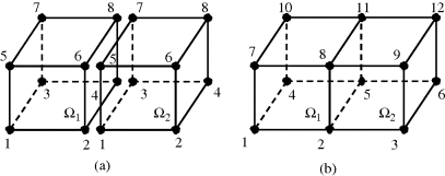
In the first step, that is, the discretization of the analysis domain Ω, the domain Ω is subdivided into a number of small subdomains. The subdomains are referred to as elements from m = 1 to M. The elements may have the shape of a tetrahedron, triangular prism, or rectangular brick, as shown in Figure 3.14. The tetrahedrons are the best suited for arbitrary-shaped volumes and the rectangular bricks are more straightforward for applying to the usual numerical human body models. In the finite element solutions, the problem is formulated in terms of the unknown function u at nodes associated with the elements. A tetrahedron has four nodes and a rectangular brick has eight nodes. A complete description of a node contains its coordinate values, local number, and global number. The local number and global number indicate the node's position in the element and in the entire system, respectively. Figure 3.15 illustrates the concept of local number and global number.
Figure 3.14 Three-dimensional element shapes: tetrahedron, triangular prism, and rectangular brick

Figure 3.15 Concept of (a) local numbering and (b) global numbering
The second step is to select an interpolation function which approximates the unknown solution within an element. The interpolation is usually selected to be a first-order polynomial for simplicity. The unknown solution in the element m can be then expressed as
where ![]() is the number of nodes in the element m,
is the number of nodes in the element m, ![]() is the value of u at node n in the element m, and
is the value of u at node n in the element m, and ![]() is the interpolation function which is nonzero only within element m. In this equation, the coefficients to be determined are
is the interpolation function which is nonzero only within element m. In this equation, the coefficients to be determined are ![]() .
.
To proceed to the third step for obtaining a system of equations, let us first define the inner product of two functions u and v, denoted by angular brackets, as
(3.77) ![]()
where Ω is the domain of u and v. With this definition, if the differential operator L satisfies
(3.78) ![]()
the following functional
(3.79) ![]()
should give the solution to Equation 3.75 at its minimum with respect to ![]() . In other words, Equation 3.75 is equivalent, in the mathematical sense, to minimizing the functional F. For the functional F to have a minimum, its first-order derivative with respect to
. In other words, Equation 3.75 is equivalent, in the mathematical sense, to minimizing the functional F. For the functional F to have a minimum, its first-order derivative with respect to ![]() should vanish.
should vanish.
In the entire analysis domain comprised of M elements, the functional F can be expressed as
and
where the domain of ![]() is Ωm. Substituting Equation 3.76 into 3.81, we have
is Ωm. Substituting Equation 3.76 into 3.81, we have
(3.82) ![]()
where ![]() is an Nm × Nm matrix and
is an Nm × Nm matrix and ![]() is an Nm × 1 column vector with
is an Nm × 1 column vector with
(3.83) ![]()
and
(3.84) ![]()
Substituting Fm into Equation 3.80 and adopting the global node numbers, we obtain
(3.85) ![]()
where ![]() is an N × N matrix with N being the total number of unknowns or nodes,
is an N × N matrix with N being the total number of unknowns or nodes, ![]() is an N × 1 unknown coefficient vector, and
is an N × 1 unknown coefficient vector, and ![]() is an N × 1 known vector. To minimize F we let its partial derivatives with respect to
is an N × 1 known vector. To minimize F we let its partial derivatives with respect to ![]() (n = 1,2,..., N) to zero. This yields a system of linear algebraic equations
(n = 1,2,..., N) to zero. This yields a system of linear algebraic equations
in matrix form.
The fourth or final step in the finite element analysis is to solve the system of Equations 3.86 for [u]. Although the dimension of the system or the number of unknowns may be as large as several hundred thousands, there are many well-developed black-box program packages available for solving it. In such a way, FEM can be used to solve the vector wave Equations 3.73 and 3.74 for propagation characteristic analysis in body area communications.
In body area propagation analysis the radiation may take place in an open region. Covering the entire domain with finite elements is impossible. So the analysis domain has to be truncated to a finite size by using a domain termination boundary. Over this terminal boundary, a radiation condition or an absorbing boundary condition must be enforced such that no reflection takes place as the wave impinges on the boundary from the inside of the domain. The simplest boundary condition is to set a circular boundary at ρ, and enforce the Sommerfeld radiation condition
(3.87) ![]()
where n is the normal to the circular boundary and k is the wavenumber. The Sommerfeld radiation condition assumes the radiating waves are purely traveling, and therefore the terminal boundary should be located at a considerable distance from the analysis object. To overcome this problem, the PML as described in the FDTD method can also be used as an absorbing boundary condition in FEM. This implementation amounts to introducing an additional layer into the finite element domain which works to attenuate the field as it penetrates into the layer.
3.4 Numerical Human Body Model
An anatomically based human body model is essential for numerical simulation in body area communications. Such a numerical human body model is developed commonly from magnetic resonance imaging (MRI) or computed tomography (CT) scans. MRI or CT provides gray-scale image data as many transverse slices, at a designated spacing, from the head to feet of the human body. The resolution in each slice is in the order of several millimeters. In general, it is easy to identify bone from CT images, but it is more difficult to segment interior organs. MRI data are generally superior to CT data in identifying interior tissues, because of their high contrast. Consequently MRI data are used more often in the development of numerical models. The drawback of MRI is that the image acquisition is time-consuming and automatic identification of various organs is difficult.
In order to develop a human body model for numerical electromagnetic analysis, original gray-scale data must be interpreted into tissue types, which is known as a process of segmentation. This is because the permittivity and conductivity are required for each tissue in solving the Maxwell equations. However, the gray scales in magnetic resonance images do not correspond to tissue types directly. Different tissues can have the same gray-scale values, which makes it impossible to automatically identify the original images into corresponding tissues or organs with sufficient accuracy using presently available image-processing techniques. All tissue- and organ-identification processing is therefore performed manually or semi-automatically, to a large extent. Guidance from medical specialists is also necessary for accurate segmentation.
The gray-scale images are first rescaled to produce appropriate cells. Each cell in the images is then identified rigorously as belonging to one type of tissue by, for example, assigning each cell a red-green-blue code that identifies the discrete tissue type of that particular cell. This process can be performed with commercial software such as Adobe Photoshop. All identified transverse images are then combined to obtain a three-dimensional numerical model. A fine adjustment is generally required to smoothly connect each slice in the three orthogonal planes (axial, sagittal, and coronal).
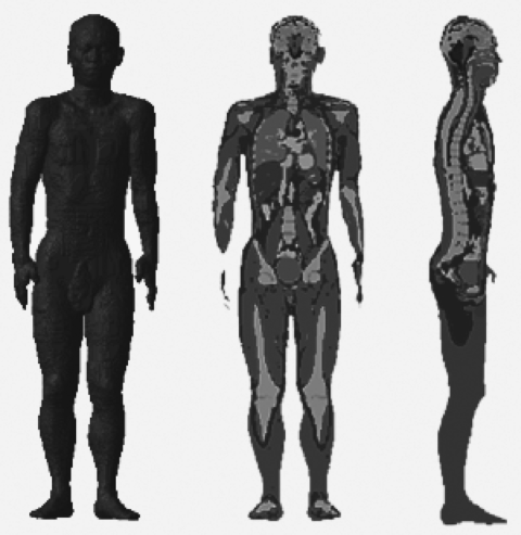
Figure 3.16 shows an example of a numerical human body model (Nagaoka et al., 2004). The human body model was developed from MRI data using the method just described. It consists of 51 tissue types such as skin, fat, muscle, bone, white matter, gray matter, heart, liver, lung, and so on. The model is comprised of a huge number of cubic cells of size 2 × 2 × 2 mm, with a very high complexity for numerical electromagnetic analysis. It can be obtained from the National Institute of Information and Communications Technology (NICT), Japan, for academic use.
Figure 3.16 Numerical human body model developed from MRI data (Nagaoka et al., 2004)
However, it is evident that the above-described approach is cumbersome and time-consuming when developing a numerical human body model. To overcome this drawback, a promising approach is to develop an anthropomorphic numerical model, which is known as the dielectric anatomical model (Mazzurana et al., 2003). In this approach, the gray scales in magnetic resonance images are correlated to the complex permittivity by some continuous transfer functions. This approach makes it possible to semi-automatically obtain a numerical human body model from the raw MRI data.
According to this approach, we first need to subsequently acquire two turbo spin-echo sequences with an echo time TE and two different repetition times TR (short and long) for the MRI data. The spin-echo signal intensity of each pixel in the magnetic resonance images is related to the spin–lattice relaxation time T1 which characterizes the human tissues. By dividing the images with short repetition time, pixel by pixel, by the images with long repetition time, we can obtain the ratio image intensity
where the gray levels in MRI data depend only on T1 and on the factor ![]() . The factor k, which depends on the type of sequence and on the acquisition parameters, is independent of the position r. Since the gray level of each pixel of the short image is lower than that of the long image,
. The factor k, which depends on the type of sequence and on the acquisition parameters, is independent of the position r. Since the gray level of each pixel of the short image is lower than that of the long image, ![]() takes values between 0 and 1.
takes values between 0 and 1.
Next, in place of the tissue segmentation and subsequent assignment of complex permittivity, we can determine the complex permittivity values automatically from T1 in the ratio images. This is because that there is a relationship to relate T1 to water content and another one to relate water content to complex permittivity. T1 is usually influenced by the frequency and the amount of water in a human body. In particular, in high water content tissues, water may exist in two states: free water, associated with a longer relaxation time; and bound water, associated with a shorter relaxation time. The measured spin–lattice relaxation time T1 is actually a weighted average of the free and bound water times. The larger the water content is, the longer the spin-lattice relaxation time T1. Based on this monotonic relationship we can derive an equation to link the water fraction of various human tissues to the relaxation time T1 by
where A and B are two factors which depend on the magnetic field strength.
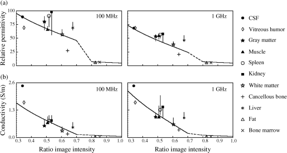
On the other hand, water content is known to be related to the complex permittivity of human tissue. Since T1 determines the gray level in the ratio image, and also is related to the water content, some continuous transfer functions such as ![]() and
and ![]() can be derived based on empirical data for some representative tissues. Figure 3.17 shows some examples for the transfer functions from the MRI ratio intensity to the relative permittivity and conductivity at frequencies of 100 MHz and 1 GHz. Symbols indicate Gabriel's data and vertical segments the literature variability (Foster and Schwan, 1996). Typical values for Equations 3.88 and 3.89 are reported as A = 0.915, B = 293 S, and
can be derived based on empirical data for some representative tissues. Figure 3.17 shows some examples for the transfer functions from the MRI ratio intensity to the relative permittivity and conductivity at frequencies of 100 MHz and 1 GHz. Symbols indicate Gabriel's data and vertical segments the literature variability (Foster and Schwan, 1996). Typical values for Equations 3.88 and 3.89 are reported as A = 0.915, B = 293 S, and ![]() = 1.04.
= 1.04.
Figure 3.17 Transfer functions from the MRI ratio intensity to (a) the relative permittivity and (b) conductivity at frequencies of 100 MHz and 1 GHz. Symbols indicate Gabriel's data and vertical segments the literature variability (Mazzurana et al., 2003). Reproduced with permission from Mazzurana M., Sandrini L., Vaccari A., Malacarne C., Cristoforetti L. and Pontalti R., “A semi-automatic method for developing an anthropomorphic numerical model of dielectric anatomy by MRI,” Physics in Medicine and Biology, 48, 3157–3170, 2003. © 2003 IOP Publishing
In such a way, we can easily obtain an anthropomorphic numerical model of dielectric anatomy from the raw MRI data for numerical electromagnetic field analysis. The dielectric anatomical model also takes into account the complex permittivity variations in every tissue.
When the frequency is sufficiently high so that the skin depth is around several millimeters, the tissue and organs inside the human body become not so important. This unimportance in internal organs is also true for on- or off-body communication scenarios. In these cases, the body externals and posture play a more important role from the point of view of electromagnetic propagation characteristics. Hence we can employ a homogeneous body model in place of the anatomical one, and set the model to have skin's permittivity and conductivity in the GHz band and muscle's permittivity and conductivity below the GHz band, in view of the possible penetration depth. In addition, at lower frequencies (around MHz), the wave can completely penetrate into the human body. In this case, two-thirds of muscle's permittivity and conductivity are known to be a good approximation for average tissue properties of the human body.
The creation of a homogeneous human body model is much simpler than the anatomical one. It is also easier to modify the body model to have various postures, whereas this is almost impossible for an anatomical model. The body model with various postures is essential for on-body propagation characterization.
A simple method for making a homogeneous human body model with postures is to use the Poser software (http://poser.smithmicro.com). It prepares some basic three-dimensional poly-mesh human figures and with it the user can simply pose the human figures to have a required posture. By saving the three-dimensional human figure to a format readable in the FDTD code, a posed human body model with homogeneous tissue can be obtained.
In conjunction with adequate human body models, the numerical electromagnetic analysis method provides an effective means for body area propagation characterization and channel modeling.
Berenger, J.P. (1994) A perfectly matched layer for the absorption of electromagnetic waves. Journal of Computational Physics, 114, 185–200.
Chakarothai, J., Wang, J., Fujiwara, O. et al. (2012) Implementation and validation of hybrid MoM-FDTD method for analysis of composite structure including inhomogeneous objects. IEICE Technical Report AP2012-7.
Foster, K.R. and Schwan, H.P. (1996) Dielectric properties of tissues, in Handbook of Biological Effects of Electromagnetic Fields (eds C. Polk and E. Postow), CRC Press, New York, pp. 25–102.
Jin F. J. (1993) The Finite Element Method in Electromagnetics, John Wiley & Sons, Ltd, New York.
Mazzurana, M., Sandrini, L., Vaccari, A. et al. (2003) A semi-automatic method for developing an anthropomorphic numerical model of dielectric anatomy by MRI. Physics in Medicine and Biology, 48, 3157–3170.
Nagaoka, T., Watanabe, S., Saurai, K. et al. (2004) Development of realistic high-resolution whole-body voxel models of Japanese adult males and females of average height and weight, and application of models to radio-frequency electromagnetic-field dosimetry. Physics in Medicine and Biology, 49, 1–15.
Rao, S.M., Wilton, D.R., and Glisson, A.W. (1982) Electromagnetic scattering by surfaces of arbitrary shape. IEEE Transactions on Antennas and Propagation, 30 (3), 409–418.
Taflove, A. and Hagness, S.C. (2000) Computational Electrodynamics: The Finite-Difference Time-Domain Method, Artech House Inc., Boston, MA.
Wang, J., Fujiwara, O., Watanabe, S., and Yamanaka, Y. (2004) Computation with a parallel FDTD system of human-body effect on electromagnetic absorption for portable telephones. IEEE Transactions on Microwave Theory and Techniques, 52 (1), 966–971.


