Chapter 6
Body Area Communication Performance
6.1 Introduction
The communication performance of a body area communication system is directly influenced by the channel it operates in. Body area channels differ from traditional wireless indoor/outdoor channels on account of the fact that great changes take place in signal propagation on or in or off the body. As a special transmission medium for wireless communication, human body tissue brings new challenges to channel modeling as well as to communication performance evaluation. Chapter 4 has generalized body area channels in the form of a static shadow fading channel and a dynamic multipath fading channel. Body area channels are characterized by different communication frequencies and communication channel position. The channel models have been further classified into different kinds according to the frequency band as well as the channel position in the body area. In this chapter, we will evaluate the communication performance in terms of frequency and communication channel position, that is, according to the following four major types: on-body UWB communication; in-body UWB communication; in-body MICS band communication; and human body communication, respectively. For in-body UWB communication, two application scenarios will be covered: in-body to on-body transmission for capsule endoscope application and in-body to off-body transmission for cardiac pacemaker application. Finally, a dual mode scheme will be described which can combine both the human body communication function and the in-body to on-body UWB/MICS communication function.
The methodology for evaluating the average bit error rate (BER) performance will be first derived in both the static channel and dynamic multipath channel. For each communication type, the average BER performance in both the static shadow fading channel and dynamic multipath fading channel will be presented in detail. Link budget analysis will then be described in terms of maximum system safety margins based on the derived average BER performance. Last but not the least, we will discuss several communication parameters including the communication distance, data rate as well as the required transmit power for all communication types in each respective section.
6.2 On-Body UWB Communication
The on-body UWB path loss model derived in Section 4.2.2 and the on-body UWB dynamic multipath fading channel model derived in Section 4.3.2 enable the analysis and evaluation of on-body UWB communication performance. In this section, we will first introduce the methodologies for evaluating the average BER performance in a static shadow fading channel and in a dynamic multipath fading channel. Then a link budget analysis will be addressed based on the derived BER performance in the on-body UWB channel. In addition, the BER performance versus communication distance will also be presented.
6.2.1 Bit Error Rate
6.2.1.1 Average BER in a Static Shadow Fading Channel
The on-body UWB path loss model of Equation 4.12 accounts for the shadowing effect on the human body. The shadowing is mainly induced by the diffraction in the shadowed regions of the body. It can directly result in variation of the received signal at the receiver front end. The instantaneous SNR is a random variable at the receiver which includes the effect of shadowing. In fact, the variation of the SNR is the direct indicator of the shadowing effect.
Equation 5.42 describes the average BER in a dynamic multipath fading channel, in which the instantaneous SNR is also a random variable at the receiver. This equation averages the bit error probability in AWGN channel over the PDF of the SNR. In fact, the conditional error probability in Equation applies as long as the received SNR is a statistical random variable with a certain PDF. Now let us derive the average BER for arbitrary on-body receiver locations. In this case the received SNR varies in a specific statistical distribution due to the shadow fading. First we write the conditional error probability expression again here as
where ![]() represents the average SNR,
represents the average SNR, ![]() is the average BER in a static shadow fading channel,
is the average BER in a static shadow fading channel, ![]() is the BER in a AWGN channel, and
is the BER in a AWGN channel, and ![]() denotes the PDF of
denotes the PDF of ![]() . As noted here, the term “average” in the error probability refers to statistical averaging over the probability distribution of the SNR. Therefore, we need to know the probability distribution of the SNR for deriving the average BER in a static shadow fading channel.
. As noted here, the term “average” in the error probability refers to statistical averaging over the probability distribution of the SNR. Therefore, we need to know the probability distribution of the SNR for deriving the average BER in a static shadow fading channel.
The derivation process is as follows:
(6.2) ![]()
(6.3) ![]()
(6.4) ![]()
(6.6) ![]()
(6.8) ![]()
(6.9) ![]()
(6.10) ![]()
(6.11) ![]()
(6.12) ![]()
(6.13) ![]()
(6.14) ![]()
(6.15) ![]()
(6.16) ![]()
(6.17) 
![]()
![]()
![]()
![]()
(6.18) ![]()
(6.19) ![]()
(6.20) ![]()
(6.21) ![]()
(6.22) ![]()
(6.23) ![]()
The above four steps describe the detailed derivation process for the average BER in a static shadow fading channel. As can be seen, the statistical characteristic of Eb/N0 is dependent on the shadowing characteristic of the path loss model. The BER performance degradation is inevitable in a static shadow fading channel compared with an AWGN channel. The standard deviation value of the shadowing will primarily determine the communication performance degradation with reference to the AWGN channel.
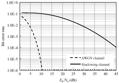
Using the derived shadowing parameters in Section 4.2.2 and the derived bit error probabilities for IR-UWB in an AWGN channel in Section 5.3.3, we can obtain the average BER performance as described above. Figures 6.1 and 6.2 show the comparisons between an ideal BER in an AWGN channel and a deteriorated average BER for binary PPM and PAM. As noted, the average BER performance of PPM in on-body UWB static shadow fading channel is 3 dB poorer than PAM. Moreover, the above derivation applies for the traditional optimum demodulation scheme. From the results, it can be noted that the average BER performance in the on-body UWB static shadow fading channel has deteriorated significantly.
Figure 6.1 BER comparison in AWGN channel and on-body UWB static shadow fading channel (σ dB = 10dB) for IR-UWB with PPM scheme
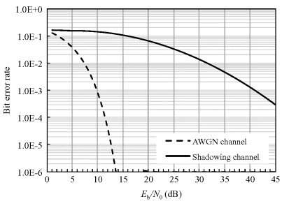
Figure 6.2 BER comparison in AWGN channel and on-body UWB static shadow fading channel (σ dB = 10 dB) for IR-UWB with PAM scheme
6.2.1.2 Average BER in a Dynamic Multipath Fading Channel
On-body UWB communication performances are mainly decided by the on-body UWB multipath propagation channel. As shown in Section 4.3.2, the multipaths in on-body UWB communication are essentially induced by the reflection due to movement of one or more parts of the body. The multipath channel makes electromagnetic waves traveling along the body reflected, diffracted, and scattered, so that a received signal ends up being the superimposition of several attenuated, delayed, and eventually distorted replicas of a transmitted waveform. System performance is therefore bound to be degraded by the distortion of pulses due to propagation over such a real channel. However, as described in Chapter 5, the performance degradation due to multipath propagation can be mitigated via multiple correlators in RAKE reception or CP in MB-OFDM demodulation if a detailed characterization of the multipath channel can be achieved at the receiver. Section 4.3.2 provides detailed parameterization for typical on-body UWB multipath channels on the upper body, which potentiates the implementation of the anti-multipath technique as well as the analysis of communication performances.
As described in Section 4.3, the RMS delay spread is a good measure of multipath spread and it gives an indication of the potential for inter-symbol interference. In fact, it is the multipath spread that restricts the practical communication performance, including data rate, communication distance, and so on. The most direct behavior is that the delay spread will put a constraint on the potential data rate. In a case where a high data rate is expected for a known on-body UWB channel, the error bits will increase and the BER performance will deteriorate.
Based on the findings in Section 4.3, the characteristics of the on-body dynamic multipath fading channels differ considerably for different propagation links due to the variability of the link geometry. Now let us focus on one of the five representative transmission links shown in Figure 4.25, that is, the chest-to-right-waist channel. The RMS delay spread for the chest-to-right-waist channel is summarized in Table 6.1. As can be seen, the RMS delay spread is around 0.47 ns. The BER performance is shown in Figure 6.3 with increasing data rate using the conventional correlation receiver described in Section. Table 6.2 shows the simulation specifications. More than 10 discrete impulse response functions are used for the BER simulation to have a statistically average performance since the BER result depends on the particular realization of the channel impulse response.
Figure 6.3 BER versus data rate performance with a correlation receiver (Wang and Wang, 2010). Reproduced with permissions from Wang Q. and Wang J., “Performance of ultra wideband on-body communication based on statistical channel model,” IEICE Transactions on Communications, E93-B, 4, 833–841, 2010
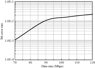
Table 6.1 FDTD-derived and modeled RMS delay spread.
| FDTD-derived | Modeled | |
| Mean | 0.469 | 0.470 |
| Standard deviation | 0.145 | 0.177 |
Table 6.2 Data rate simulation specifications.
| UWB frequency band (GHz) | 3.1–10.6 |
| Pulse | Second derivative Gaussian pulse |
| Chips per bit | 16 |
| Modulation scheme | PPM |
| Receiver | Correlation detection |
The BER performance is obtained using the communication simulation tool Advanced Design System (ADS, Agilent) (Wang and Wang, 2010). The BER performance in Figure 6.3 is under the FCC permissible maximum UWB transmitting power. As expected, when the data rate goes up to 90 Mbps, the BER becomes even worse than 0.01.
In error correction theory, the probability of error 0.01 or 0.001 is usually taken as a criterion threshold in which the error correction code can work effectively. For example, in Bic, Duponteil, and Imbeaux (1991) it is shown that the intersection point of BER with coding and BER without coding, that is, the point of coding gain equal to zero, is between BER = 0.01 and BER = 0.001 for forward error correction. It is therefore reasonable to use 0.01 and 0.001 as indices. That is to say, as long as the BER is not worse than 0.01 or 0.001, the error bits can be detected and then corrected using specific error correction codes. In turn, if the error probability is very high and surpasses the threshold, the error correction coding may not be practical.
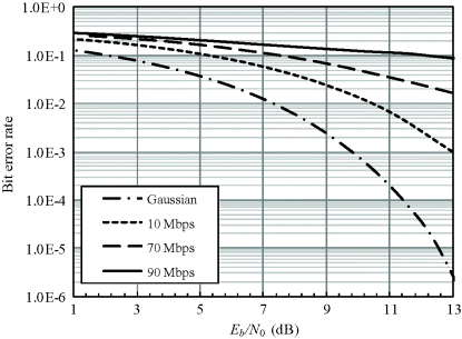
Based on the error correction theory, we can conclude that the maximum desirable data rates for the chest-to-right-waist channel with correlation receiver are 70 Mbps and 90 Mbps, which correspond to a BER threshold of 0.001 and 0.01, respectively.
At the two maximum data rates, the BER performance with a correlation receiver is given in Figure 6.4 to compare with the ideal performance under AWGN channel. Meanwhile, the BER performance with correlation receiver at 10 Mbps is also shown in Figure 6.4 as a representative data rate. It can be noted that the performance of the correlation receiver is not so satisfactory in the multipath-affected on-body channel since the BER performance deteriorated badly. Actually, the conventional correlation receiver is not appropriate for the multipath-affected on-body channel since its structure foresees the presence of a correlator that is matched to one single waveform, while in the multipath-affected on-body channel the superposition of multiple signals is not evitable. An advanced receiver structure is therefore needed to improve the communication performance. Yet, the simple structure of a correlation receiver still has an advantage for on-body communications.
Figure 6.4 BER performance at different data rates with a correlation receiver
As described in Chapter 5, the performance degradation can be mitigated using a RAKE receiver if a detailed characterization of the multipath-affected channel is known. The RAKE receiver can improve the BER performance since it takes advantage of multipaths to enhance the whole SNR. On the other hand, the adoption of a RAKE considerably increases the complexity of the receiver structure. This complexity increases with the number of multipath components to be analyzed and the corresponding finger number, and can be reduced by decreasing the number of components processed by the receiver. However, a reduction of the number of multipaths to be analyzed leads to a decrease in energy collected by the receiver.
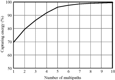
For a known on-body UWB dynamic multipath fading channel, it is possible to derive a reasonable finger number in order to have a rational use of the RAKE structure. Based on the previous FDTD-calculated results in Section 4.3.2, the probability of multipaths as well as the captured energy of multipaths can be calculated for the chest-to-right-waist channel. Figure 6.5 shows the probability versus the number of multipaths. Four effective multipaths have the highest probability in all of the possible multipaths. Figure 6.6 shows the energy percentage captured by multipaths. As noted, about 80% of the received energy is captured by the first two multipaths, and 92% of the received energy is captured by the first four multipaths. Therefore, 2-finger and 4-finger RAKE receivers, which correspond to the first two and first four multipath components, can be reasonably employed.
Figure 6.5 Probability versus number of multipaths
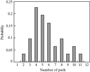
Figure 6.6 Energy percentage captured by multipaths
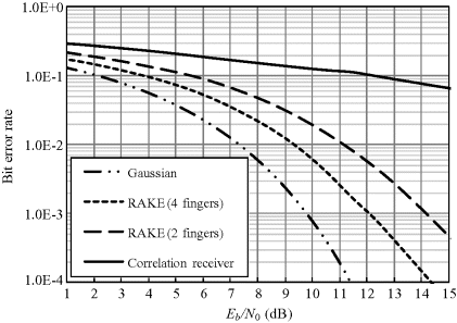
Assume that the optimum MRC scheme is used in the simulation set-up. Figures 6.7–6.9 show the BER performances with 2- and 4-finger RAKE receivers at the data rates 10, 70 and 90 Mbps, respectively. Here 10 Mbps is also evaluated as a representative data rate for on-body communication. As expected, both the 2-finger and 4-finger RAKE receiver significantly improves the BER performance compared with the conventional correlation receiver. At a data rate of 10 Mbps, the degradation in performance of the 2-finger and 4-finger RAKE receivers is less than 2 dB at a BER of 0.01 with respect to the ideal AWGN channel, while at a data rate of 70 and 90 Mbps, the performance degradations are less than 3 and 4 dB, respectively. The BER of the 4-finger RAKE receiver is superior to that of the 2-finger RAKE receiver. At a BER of 0.01, the performance degradation of the 4-finger RAKE receiver for 10 Mbps is about 1 dB and for 70 and 90 Mbps is about 2 dB compared with the ideal Gaussian channel. These results demonstrate that both the 2-finger and 4-finger RAKE receivers are effective in the on-body multipath channel and they can considerably improve the communication performance.
Figure 6.7 BER at a data rate of 10 Mbps
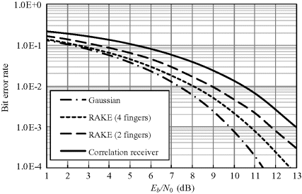
Figure 6.8 BER at a data rate of 70 Mbps (Wang and Wang, 2010). Reproduced with permissions from Wang Q. and Wang J., “Performance of ultra wideband on-body communication based on statistical channel model,” IEICE Transactions on Communications, E93-B, 4, 833–841, 2010
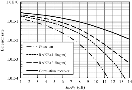
Figure 6.9 BER at a data rate of 90 Mbps (Wang and Wang, 2010). Reproduced with permissions from Wang Q. and Wang J., “Performance of ultra wideband on-body communication based on statistical channel model,” IEICE Transactions on Communications, E93-B, 4, 833–841, 2010
However, as described above, simplicity in the device structure is also an important issue which cannot be ignored. The complicated structure for the 4-finger RAKE receiver may hinder its application in wearable body area communication. In this sense, the 2-finger RAKE receiver can be an option as a compromise between the communication performance and structure complication, since it can get satisfactory performance whilst having a relatively simple structure compared with the 4-finger RAKE receiver.
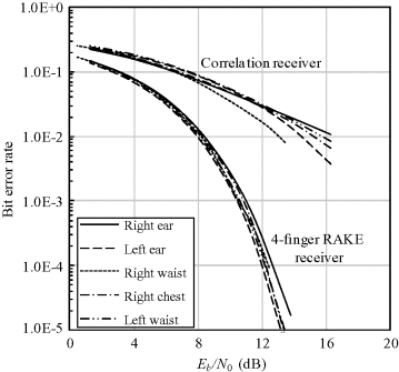
Based on the previous analysis taking the chest-to-right-waist channel as the example, now let us take a brief look at the BER performance of the other four channels corresponding to receiver locations at the left ear, right ear, right chest and left waist, respectively. Figure 6.10 shows the energy percentage captured by multipaths. As noted, more than 95% of the received energy can be captured by the first four multipaths for the other four channels. Figure 6.11 compares the BER performance of all five channels using a correlation receiver and 4-finger RAKE receiver, respectively, and the corresponding data rate is 70 Mbps. The BER performance for the five channels is very similar using a 4-finger RAKE receiver since over 95% energy has been captured even though the channel model parameters are different as shown in Table 4.10. The BER performance using a correlation receiver differs slightly since it mainly depends on the captured energy by the first multipath.
Figure 6.10 Energy percentage captured by multipaths for the five transmission links
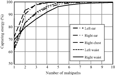
Figure 6.11 BER at a data rate of 70 Mbps for the five communication links
6.2.2 Link Budget
A link budget is the accounting of all of the gains and losses from the transmitter, through the transmission medium to the receiver in a communication system. It accounts for the attenuation of the transmitted signal due to propagation, as well as the antenna gains, feedline and miscellaneous losses. In order to analyze the link budget for an on-body UWB channel, apart from the derived path loss, the possible signal power as well as the noise characteristics also have to be calculated.
The UWB emission mask issued by the FCC (2002) is designed to make UWB radio signals coexist with other radio signals. This emission mask imposes a limit on the maximum allowed transmitting power at any given frequency. For the whole UWB frequency band, that is, from 3.1 to 10.6 GHz, the maximum emission power density is not allowed to exceed −41.3 dBm/MHz. Note that the FCC emission mask refers to a unilateral PSD PM(f) =− 41.3 dBm/MHz; therefore, the maximum allowed transmitting power ![]() for a signal occupying the whole UWB frequency band is (Benedetto and Giancola, 2004)
for a signal occupying the whole UWB frequency band is (Benedetto and Giancola, 2004)
that is
Similarly, if the signal bandwidth is 500 MHz locating within the frequency range 3.1–10.6 GHz, which corresponds to the definition for the MB-UWB solution, the maximum allowed transmitting power ![]() is
is
(6.26) ![]()
.
The FCC regulation illustrates the fact that the UWB radio signal must meet the emission mask and the maximum allowed transmitting power requirements. Signal power up to the maximum allowed transmitting power can be considered as the best case in performance analysis for the UWB radio link. Given the allowed maximum power, we can now evaluate the system margin when a predetermined probability of error must be guaranteed at the receiver.
First, let us determine the noise characteristics at the receiver. Let us assume that the only noise source at the receiver is AWGN. This noise is typically thermal, introduced by the receiving antenna and the front-end circuit of the receiver. The thermal noise PSD expressed in joules, that is, W/Hz is given by:
where ![]() is the receiving antenna temperature, T0 = 300 K is the environment temperature,
is the receiving antenna temperature, T0 = 300 K is the environment temperature, ![]() is the Boltzmann constant, and finally,
is the Boltzmann constant, and finally, ![]() is the noise figure of the receiving device. Note that
is the noise figure of the receiving device. Note that ![]() here is the unilateral PSD and the corresponding bilateral PSD is half.
here is the unilateral PSD and the corresponding bilateral PSD is half.
Since the receiving device is worn on the human body, a reasonable hypothesis is introduced that ![]() K. Equation 6.27 can therefore be rewritten as
K. Equation 6.27 can therefore be rewritten as
(6.28) ![]()
and in decibels
(6.29) ![]()
Secondly, the link Eb/N0 can be determined at a given data rate ![]() for the communication system.
for the communication system.
Based on Equation 4.2, the received power at the receiver front end can be more accurately rewritten as follows
which includes all the gains and losses from the transmitter and receiver as well as the miscellaneous losses and the explanation for each physical quantity can be found in Table 6.3. Then the link SNR or Eb/N0 in decibels is
Table 6.3 Parameters for on-body UWB link budget analysis.
| Transmitter and receiver | |
| Frequency (GHz) | 3.1–10.6 |
| Transmitter output power |
−2.55 |
| Transmitter antenna gain |
0 |
| Transmitter losses |
0 |
| Miscellaneous losses |
3 |
| Receiver antenna gain |
0 |
| Receiver losses |
0 |
| Standard temperature T (K) | 300 |
| Receiver noise figure NF (dB) | 6 |
| Boltzmann constant k (J/K) | 1.38E-23 |
| Signal quality | |
| Bite error rate | 10−3 |
| 38 (PAM, correlation receiver) | |
| 41 (PPM, correlation receiver) | |
| 11.8 (PPM-TH, 2-finger RAKE 10 Mbps) | |
| 10.8 (PPM-TH, 4-finger RAKE 10 Mbps) | |
| 13.2 (PPM-TH, 2-finger RAKE 70 Mbps) | |
| 11.7 (PPM-TH, 4-finger RAKE 70 Mbps) | |
| 14.2 (PPM-TH, 2-finger RAKE 90 Mbps) | |
| 12.1 (PPM-TH, 4-finger RAKE 90 Mbps) | |
| Coding gain (dB) | 0 |
Finally, we define a system margin ![]() by
by
where ![]() denotes the required Eb/N0 for obtaining a specific probability of error.
denotes the required Eb/N0 for obtaining a specific probability of error.
In Equation 6.32, if the link Eb/N0 exceeds the required ![]() , which means system margin
, which means system margin ![]() , the wireless communication is feasible. The larger the system margin, the more reliable and robust the communication transmission.
, the wireless communication is feasible. The larger the system margin, the more reliable and robust the communication transmission.
Similarly, according to the error correction theory, here we use BER = 0.001 as the predetermined probability of error threshold. For a correlation receiver, the average BER in the on-body UWB static shadow fading channel is shown in Figures 6.1 and 6.2. As noted, the required Eb/N0 for binary PAM and PPM are 38 and 41 dB, respectively. Based on the system parameters in Table 6.3, Figures 6.12 and 6.13 show the dependence of the system margin on the distance with data rates of 0.1, 1 and 10 Mbps. It can be found that the system has a margin larger than 0 dB for PPM and PAM signals at a communication distance of about 0.3 m and 0.4 m, respectively, for data rate less than 1 Mbps, while for data rate of 10 Mbps, the communication distance is greatly reduced to 0.2 m or less.
Figure 6.12 Maximum system safety margins as a function of the distance in on-body static shadow fading channel for PPM signals at different data rates
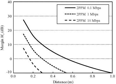
Figure 6.13 Maximum system safety margins as a function of the distance in on-body static shadow fading channel for PAM signals at different data rates
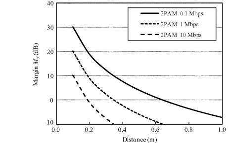
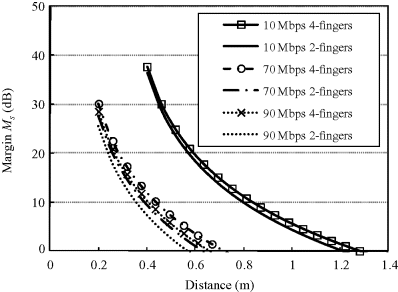
On the other hand, in a dynamic multipath fading environment, an advanced receiver structure like the RAKE receiver can be expected to provide a better system margin. Based on the results in Figures 6.7–6.9, we can summarize the required Eb/N0 for 2-finger and 4-finger RAKE receivers with different data rates as shown in Table 6.3. The system margin is shown in Figure 6.14. As expected, the communication distance has been largely improved with the 2-finger or 4-finger RAKE receivers. At a communication distance of nearly 0.6 m, the maximum system margin can be larger than 0 dB even at a data rate as high as 90 Mbps. Within a communication distance of 1.3 m, the system margin is always larger than 0 dB at a data rate of 10 Mbps. In fact, a distance of 1.3 m can nearly cover all communication ranges on the human body. In the link budget analysis, keep in mind that the available maximum power (−2.55 dBm) is fully exploited. In addition, reducing the data rate can effectively increase the maximum communication distance.
Figure 6.14 Maximum system safety margins as a function of the distance in on-body dynamic multipath fading channel for PPM signals with RAKE receiver
6.2.3 Maximum Communication Distance
Figures 6.7–6.9 describe the relationship between the average ![]() and the average BER in multipath fading channels. Based on the path loss Equation 4.10 and the maximum allowed transmitting power Equations 6.24 and 6.25, the maximum receiving power can be obtained based on Equation 6.30 and therefore the
and the average BER in multipath fading channels. Based on the path loss Equation 4.10 and the maximum allowed transmitting power Equations 6.24 and 6.25, the maximum receiving power can be obtained based on Equation 6.30 and therefore the ![]() term can be derived as a function of propagation distance d as follows
term can be derived as a function of propagation distance d as follows
where the gains and losses from the transmitter and receiver as well as the miscellaneous losses in Equation 6.30 are assumed to be zero. In this case, based on Equation 6.33, we can get the average BER as a function of propagation distance at a given data rate fb. These analysis and derivation procedures hold, given that there will not be a big difference in the channel statistical characteristics when the communication distance spreads to the whole body, which is basically reasonable.
Figures 6.15–6.17 show the BER versus communication distance at data rates of 10, 70 and 90 Mbps, respectively, for PPM correlation detection. For ensuring a BER of 0.001, at a data rate of 10 Mbps, the maximum communication distance with correlation receiver is about 1.1 m while with RAKE receiver (4-finger) is about 1.3 m. At a data rate of 70 Mbps, the maximum communication distance with the correlation receiver deteriorates heavily while with a RAKE receiver it is about 0.7 m. At a data rate of 90 Mbps, similar behavior holds and the distance with correlation receiver deteriorates heavily and the distance with a RAKE receiver is reduced to 0.65 m.
Figure 6.15 BER versus distance at a data rate of 10 Mbps
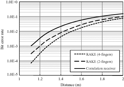
Figure 6.16 BER versus distance at a data rate of 70 Mbps (Wang and Wang, 2010). Reproduced with permissions from Wang Q. and Wang J., “Performance of ultra wideband on-body communication based on statistical channel model,” IEICE Transactions on Communications, E93-B, 4, 833–841, 2010
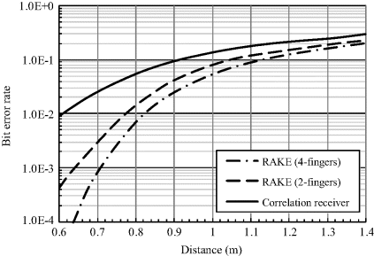
Figure 6.17 BER versus distance at a data rate of 90 Mbps (Wang and Wang, 2010). Reproduced with permissions from Wang Q. and Wang J., “Performance of ultra wideband on-body communication based on statistical channel model,” IEICE Transactions on Communications, E93-B, 4, 833–841, 2010
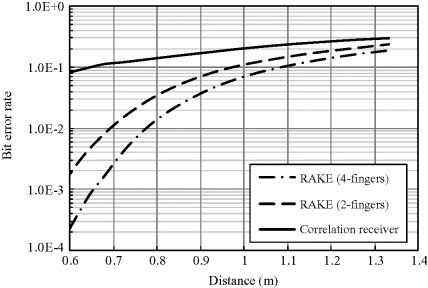
Table 6.4 gives the quantitative description of the communication distances at two BER thresholds. At the given BER thresholds and the given maximum data rate, the communication distance is around 0.6 m. This means that under the FCC emission spectral mask, the effective communication distance for UWB-PPM-TH with 2-finger and 4-finger RAKE receivers is at least 0.6 m on the human body at the maximum data rate. If a lower data rate such as 10 Mbps is acceptable, the communication distance on the human body could be longer than 1.3 m.
Table 6.4 Maximum communication distances at different data rates for PPM.

The BER versus distance performance with different data rates in Figures 6.15–6.17 are based on the path loss characteristic mainly on the front side of the human body. If the communication link is over a longer communication distance, the path loss will increase. Under the condition that the maximum transmitting power is maintained, in order to keep the same BER at 0.01 or 0.001, the data rate has to be decreased to compensate for the power loss due to the longer communication distance.
6.3 In-Body UWB Communication
The in-body UWB channel models enable the analysis and evaluation of communication performances for capsule endoscope and cardiac pacemaker applications. In this section, with the same methodology as described in the previous section, we will derive the average BER performances for the in-body UWB channels. We will also conduct a link budget analysis based on the derived BER performances, and discuss the relationship of the data rate versus required transmitting power.
6.3.1 Bit Error Rate
6.3.1.1 In-Body to On-Body Transmission for Capsule Endoscope Application
The in-body to on-body channel model can be used for the scenario of a capsule endoscope application. In this application, the SNR variation is mainly induced by the transmitter locations inside the body. The transmitted signals propagate through different tissues and organs due to the different transmitting locations of the swallowed capsule moving along the digestive organs. This SNR variation here is referred to as the shadow fading. In order to derive the average BER with this randomly varying SNR, we should know the PDF of the SNR. It has been derived that the shadow fading follows a log-normal distribution. According to the same derivation process described in Section 6.2.1, we can obtain the average BER performance for representative UWB modulation schemes.
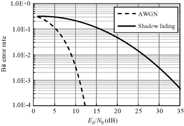
Figures 6.18 and 6.19 show the comparisons between an ideal BER in an AWGN channel and a deteriorated average BER for IR-UWB with PPM and OOK, respectively. In both schemes noncoherent energy detection is employed at the receiver. As noted, the average BER performance of OOK is 3 dB lower in comparison with that of PPM. This is because with the same data rate and noise power in the two considered schemes, the bandwidth per bit with PPM is twice that with OOK, which contributes to a half noise power spectral density for PPM. From the results, it can be noted that the average BER performance in the in-body to on-body UWB channel for capsule endoscopy has deteriorated significantly.
Figure 6.18 BER comparison in AWGN channel and in-body shadow fading channel for IR-UWB with PPM scheme and noncoherent detection
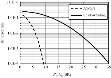
Figure 6.19 BER comparison in AWGN channel and in-body shadow fading channel for IR-UWB with OOK scheme and noncoherent detection
Diversity reception is an effective means of improving the BER performance. Diversity reception refers to a method of improving the reliability of a signal by combining two or more communication channels with different characteristics. This can be achieved by placing two or more antennas at the receiver, which is known as spatial diversity reception. The analysis model shown in Figure 4.6 agrees with this placement requirement. The combining method considered here is MRC in terms of spatial diversity. It represents a theoretically optimal combiner compared with the other diversity schemes in which the desired SNR can be maximized over fading channels in a communication system.
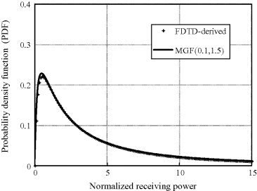
Based on the in-body to on-body channel characteristics derived in Sections 4.2.3 and 4.3.3, the combined signal with MRC diversity over two log-normal distributed channels can be denoted as a log-normal sum distribution. The derivation of this log-normal sum PDF is of great importance for evaluating the average BER in this in-body to on-body channel. Given the importance of the log-normal sum distribution in analyzing this in-body to on-body wireless system performance, effort has to be devoted to derive the PDF of the log-normal sum distribution. However, as stated in Section 5.4, closed-form theoretical expressions for log-normal sum PDF are unknown. In contrast, an approximation method using the MGF is an analytical and flexible approach in which the log-normal sum is still approximated as a log-normal distribution. This method matches a short Gauss–Hermite approximation of the MGF of the log-normal sum with that of a log-normal distribution. The mean μY and standard deviation σY in decibels in the log-normal sum PDF are obtained from Equation 5.47. The Hermite integration order N and parameter Sm for adjusting the weighted integrals of the short Gauss–Hermit integration play an important role in an accurate log-normal sum approximation. In the in-body to on-body channel, based on the fitting accuracy to the FDTD-derived PDF of the received power, the parameter Sm is determined as (S1, S2) = (0.1, 1.5), and N is determined as six. Then the nonlinear equation shown as Equation 5.47 with the unknowns μY and σY can be numerically solved, for example, using fsolve function in MATLAB®.
Figure 6.20 shows the PDF of the received power based on FDTD-derived data and that approximated by the log-normal sum approximation with MGF (Shi, Anzai, and Wang, 2011). The log-normal sum approximation corresponds to the MRC diversity reception of Rx1 and Rx2 in Figure 4.6. The approximated two parameters μ and σ in the log-normal sum for MRC diversity are shown in Table 6.5. As can be seen from Figure 6.20, this method gives a very good approximation to the FDTD-derived PDF. In addition, compared with the results in Table 6.5 for a single branch, we can observe that the parameter σ for MRC diversity becomes smaller.
Table 6.5 Parameters of the log-normal distribution.
| μ | σ | |
| Rx1 | 0 | 1.88 |
| Rx2 | 0 | 1.76 |
| Rx1 and Rx2 | 1.19 | 1.38 |
Figure 6.20 PDF of the received power based on FDTD-derived data and that approximated by the log-normal sum approximation with MGF
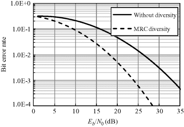
By using the log-normal sum PDF with approximated parameters in Table 6.5 and the bit error probability for PPM or OOK in AWGN channel with noncoherent detection, we can calculate the average BER for MRC diversity of Rx1 and Rx2 with Equation 6.1. The average BER performances of MRC diversity are shown in Figures 6.21 and 6.22, respectively, for the IR-UWB with PPM and OOK schemes. Significant BER improvements are obtained around 10 dB for both PPM and OOK at BER of 10−3, and a diversity gain of 2 is achieved.
Figure 6.21 Average BER performances of MRC diversity for IR-UWB with PPM scheme and noncoherent detection
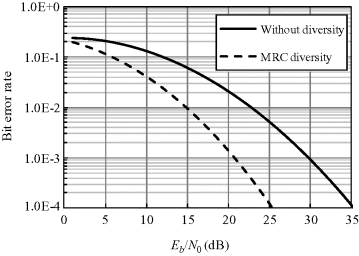
Figure 6.22 Average BER performances of MRC diversity for IR-UWB with OOK scheme and noncoherent detection
It should be noted, however, that the theoretical derivation of the log-normal sum distribution assumes statistical independence between the two received signals. This is not really true because a correlation coefficient between two single received signals may exist. This reduces the diversity effect. Such two channels which have a smaller correlation coefficient should therefore be chosen to obtain an effective diversity improvement.
6.3.1.2 In-Body to Off-Body Transmission for Cardiac Pacemaker Application
The details of the in-body to off-body channel model for the cardiac pacemaker application are given in Sections 4.2.3 and 4.3.3. The SNR variation is mainly due to the shadowing of various tissues at different transmitter or receiver locations. A two-path impulse response model is sufficient to represent the channel characteristics. The corresponding parameters for the statistical distributions are shown in Table 4.13.
With the same methodology and approach as in the in-body to on-body case, we can derive the BER performance using Equation 6.1. However, instead of the theoretical analysis approach, we here employ computer simulation to derive the BER performance (Wang, Masami, and Wang, 2011). This approach gives the same BER result in principle as the theoretical analysis approach.
The transmitter still adopts the IR-UWB with PPM scheme, and the receiver employs correlation detection. Table 6.6 gives the simulation specifications for the communication performance evaluation.
Table 6.6 Simulation specifications.
| Frequency band (GHz) | 3.4–4.8 |
| Pulse shape | Second derivative Gaussian pulse |
| Pulse width (ns) | 2.1 |
| Modulation scheme | IR-UWB with PPM |
| Data rate (Mbps) | 10 |
| Chip period (ns) | 12.5 |
| Chips per bit | 8 |
| Receiver structure | Correlation detection or RAKE reception |
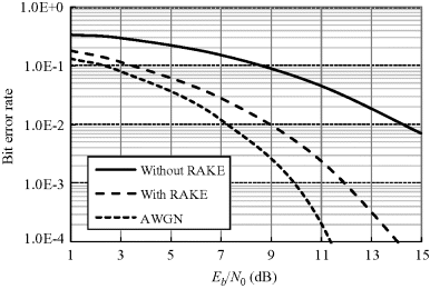
The BER performance in the in-body to off-body chest channel is shown in Figure 6.23. It is an average BER for more than 20 discrete impulse responses induced with the parameters in Table 4.13. This is because the BER depends on the particular realization of the channel impulse response. Compared with the capsule endoscope channel, the average BER performance is much better because of the smaller path loss in the chest channel. However, an Eb/N0 of about 18 dB is still required to obtain a BER of 0.001, which should be attributed to the multipath influence.
Figure 6.23 Average BER performances of 2-finger RAKE receiver for IR-UWB with PPM scheme and correlation detection
In an IR-UWB system, the RAKE receiver takes advantage of multiple correlators to cope with the multipath problems. To make a RAKE receiver work, different multipath components of the same transmitted pulse have to be analyzed separately and eventually combined. However, in the UWB low band system, the pulse width is around 2.1 ns, while the inter-path delay may be smaller. This means that it is almost impossible to separate each multipath from the received signals because the pulse width may be larger than the inter-path delay. However, the RAKE receiver can work effectively if it has prior knowledge of the multipaths.
Based on the characterization of the in-body chest channel, the first two paths dominate and the inter-path delay between them is around 1.43 ns with a very small deviation. It is therefore reasonable to use a 2-finger RAKE receiver and fix the time delay of the second finger to 1.43 ns. Such a RAKE structure can avoid the channel estimation for the arrival time of the multipath components and significantly reduces the receiver complexity. The simulated average BER is shown in Figure 6.23 for the 2-finger RAKE receiver. The BER performance is effectively improved nearly 6 dB at a BER of 0.001 compared with that without RAKE reception. The degradation in performance of the 2-finger RAKE receiver is <2 dB with respect to the correlation receiver in an ideal AWGN channel.
6.3.2 Link Budget
6.3.2.1 In-Body to On-Body Transmission for Capsule Endoscope Application
In order to analyze the link budget for the in-body to on-body transmission in UWB low band for capsule endoscope application, in addition to the derived path loss, the possible signal power and noise characteristics also have to be calculated.
The UWB emission mask issued by the FCC imposes the limit on the maximum allowed transmitting power. For the UWB low band, for example, from 3.4 to 4.8 GHz, the maximum allowed transmitting power is 0.1 mW or −10 dBm. Given the allowed maximum power, we can evaluate the system margin when a predetermined probability of error must be guaranteed at the receiver.
As described in Section 6.2, we use Equation 6.30 to obtain the received power under the maximum transmitting power, and Equation 6.31 to obtain the link SNR or Eb/N0. With BER = 0.001 as the predetermined BER threshold, we can get the required Eb/N0 of IR-UWB with PPM and OOK for noncoherent energy detection. The corresponding Eb/N0 values are 30 and 33 dB, respectively, without diversity, and 21 and 24 dB, respectively, with MRC diversity.
Using the assumed system parameters in Table 6.7, Figures 6.24 and 6.25 show the dependence of system margin on distance with data rates of 0.1, 1 and 10 Mbps for IR-UWB with PPM and OOK, respectively. It can be found that, at a data rate of 1 Mbps, the system has a margin larger than 0 dB for PPM at a distance of 9 cm and for OOK at a distance of 8 cm both from the body surface. If the data rate is increased to 10 Mbps, the possible communication distance will be limited to only 6.5 cm for PPM and 6 cm for OOK. These results suggest that a further BER improvement is necessary to make the data transmission from the digestive organs possible. Figures 6.26 and 6.27 show the dependence of system margin on distance with the MRC diversity reception. Such an improved receiver structure provides a better system margin. As can be seen, in almost all of the transmitter locations inside the digestive organs which are usually within 15 cm from the body surface, a data rate of 0.1 Mbps can always have a system margin larger than 0 dB for PPM with 2-branch MRC diversity. When the data rate is increased to 1 and 10 Mbps, however, the corresponding communication distances will be reduced to 11.5 and 8.5 cm, respectively. The possible communication distance for OOK is somewhat shorter compared with PPM. Although the 2-branch spatial diversity has improved the link budget effectively, it seems insufficient to secure a reliable wireless link for the capsule endoscope application. A higher order diversity or larger transmitting power is required for a high data rate transmission.
Figure 6.24 Dependence of system margin on distance for PPM-IR-UWB
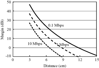
Figure 6.25 Dependence of system margin on distance for OOK-IR-UWB
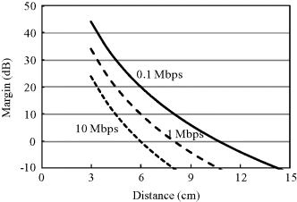
Figure 6.26 Dependence of system margin on distance for PPM-IR-UWB with MRC diversity
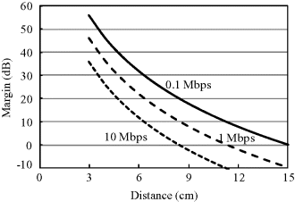
Figure 6.27 Dependence of system margin on distance for OOK-IR-UWB with MRC diversity
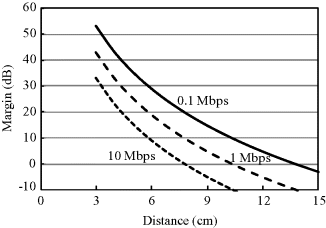
Table 6.7 Parameters for in-body to on-body UWB link budget analysis.
| Transmitter and receiver | |
| Frequency (GHz) | 3.4–4.8 |
| Transmitter output power |
−10 |
| Transmitter antenna gain |
0 |
| Receiver antenna gain |
0 |
| Standard temperature T (K) | 300 |
| Receiver noise figure NF (dB) | 6 |
| Boltzmann constant k (J/K) | 1.38E-23 |
| Signal quality | |
| Bite error rate | 10−3 |
| 30 (PPM, noncoherent detection) | |
| 33 (OOK, noncoherent detection) | |
| 21 (PPM, 2-branch MRC diversity) | |
| 24 (OOK, 2-branch MRC diversity) | |
| Coding gain (dB) | 0 |
The above analysis is under the condition that the allowable maximum transmitting power is −10 dBm based on the FCC UWB regulation. However, this regulation is defined in an indoor environment. For a UWB transmitter inside the human body, the signals arriving at the body surface will be largely attenuated due to the lossy tissues. This means that a larger transmitting power may be allowed as long as the signals at the body surface are sufficiently weak. It is therefore meaningful to clarify the relationship between the data rate and the required transmitting power. Under the 2-branch diversity reception, we use Equation 6.33 to derive the data rate fb. Here ![]() is set to be
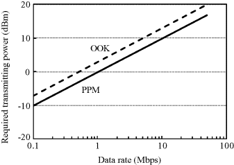
is set to be ![]() to obtain a BER of 0.001, that is, 21 dB for IR-UWB with PPM and 24 dB for IR-UWB with OOK. Figure 6.28 shows the required transmitting power as a function of data rate at a communication distance of 15 cm, which covers almost all of the possible distance for a capsule endoscope application. The result indicates a required transmitting power of at least 10 dBm (10 mW) for achieving a data rate as high as 10 Mbps for the in-body to on-body transmission. Such a data rate can be expected to provide a high-quality image transmission for a capsule endoscope application. Moreover, if the transmitting power is allowed up to 20 dBm, the data rate may achieve 50 Mbps so that a real-time transmission for uncompressed capsule images becomes possible.
to obtain a BER of 0.001, that is, 21 dB for IR-UWB with PPM and 24 dB for IR-UWB with OOK. Figure 6.28 shows the required transmitting power as a function of data rate at a communication distance of 15 cm, which covers almost all of the possible distance for a capsule endoscope application. The result indicates a required transmitting power of at least 10 dBm (10 mW) for achieving a data rate as high as 10 Mbps for the in-body to on-body transmission. Such a data rate can be expected to provide a high-quality image transmission for a capsule endoscope application. Moreover, if the transmitting power is allowed up to 20 dBm, the data rate may achieve 50 Mbps so that a real-time transmission for uncompressed capsule images becomes possible.
Figure 6.28 Required transmitting power versus data rate at an in-body to on-body communication distance of 15 cm for MRC diversity receiver
6.3.2.2 In-Body to Off-Body Transmission for Cardiac Pacemaker Application
As described in the previous subsection, the maximum allowed transmitting power is 0.1 mW or −10 dBm for the UWB low band. From Equation 6.30 we can obtain the received power when the maximum permissible power is transmitted, and from Equation 6.31 we can obtain the link SNR or Eb/N0. Also with BER = 0.001 as the predetermined threshold, we can get the required Eb/N0 for the in-body to off-body transmission for a cardiac pacemaker application. Based on the BER performance in Figure 6.23, the corresponding Eb/N0 values are 18 dB without RAKE reception and 12 dB with 2-finger RAKE reception, respectively, for the IR-UWB with PPM scheme and correlation detection.
Using the assumed system parameters in Table 6.8, Figure 6.29 shows the dependence of system margin on distance between the implant transmitter and the off-body receiver with data rates of 0.1, 1 and 10 Mbps for PPM without RAKE reception. It can be seen that the system always has a margin larger than 0 dB within an off-body distance of 40 cm for the transmission from the chest, even at a data rate as high as 10 Mbps. With the employment of 2-finger RAKE reception, as shown in Figure 6.30, the system margin is increased to 10 dB at 10 Mbps and the farthest communication distance of 40 cm. These link budget results demonstrate that a reliable wireless link in the UWB low band is feasible for a cardiac pacemaker application.
Figure 6.29 Dependence of system margin on distance for PPM-IR-UWB without RAKE reception
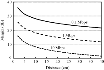
Figure 6.30 Dependence of system margin on distance for PPM-IR-UWB with RAKE reception
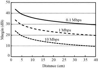
Table 6.8 Parameters for in-body to off-body UWB link budget analysis.
| Transmitter and receiver | |
| Frequency (GHz) | 3.4–4.8 |
| Transmitter output power |
−10 |
| Transmitter antenna gain |
0 |
| Receiver antenna gain |
0 |
| Standard temperature T (K) | 300 |
| Receiver noise figure NF (dB)] | 6 |
| Boltzmann constant k (J/K) | 1.38E-23 |
| Signal quality | |
| Bite error rate | 10−3 |
| 18 (PPM, correlation detection) | |
| 12 (PPM, 2-finger RAKE) | |
| Coding gain (dB) | 0 |
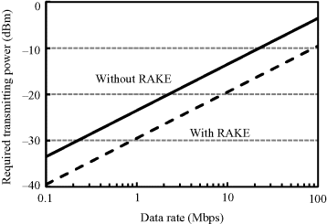
On the other hand, we give the relationship between the data rate and required transmitting power for possible transmission at higher data rate. This relationship can be derived from Equation 6.33 with the path-loss term replaced by Equation 4.14. Here ![]() is set to be
is set to be ![]() to obtain a BER of 0.001, that is, 18 dB for without RAKE reception and 12 dB for with 2-finger RAKE reception. Figure 6.31 shows the required transmitting power as a function of data rate at a communication distance of 40 cm between the implant transmitter and the off-body receiver. The result indicates that, under the maximum allowed transmitting power of −10 dBm, a data rate up to 100 Mbps is possible with RAKE reception for the in-body to off-body UWB transmission for a cardiac pacemaker application.
to obtain a BER of 0.001, that is, 18 dB for without RAKE reception and 12 dB for with 2-finger RAKE reception. Figure 6.31 shows the required transmitting power as a function of data rate at a communication distance of 40 cm between the implant transmitter and the off-body receiver. The result indicates that, under the maximum allowed transmitting power of −10 dBm, a data rate up to 100 Mbps is possible with RAKE reception for the in-body to off-body UWB transmission for a cardiac pacemaker application.
Figure 6.31 Required transmitting power versus data rate at an in-body to off-body chest channel with a communication distance of 40 cm for PPM-IR-UWB
6.4 In-Body MICS-Band Communication
In-body MICS-band communication covers the scenario of a wireless capsule endoscope application. In this section, with the same methodology as in the previous sections, we will derive the average BER performance for the in-body MICS-band channel. We will also conduct a link budget analysis based on the derived BER performances, and discuss the data rate versus required transmitting power.
6.4.1 Bit Error Rate
On account of the deeper penetration of signals compared with UWB, the MICS band should provide better performance for a real time picture or video transmission from the digestive organs, although the available bandwidth becomes narrow. The SNR variation with the capsule endoscope movement along the digestive organs is referred to as shadow fading here. Since it follows a log-normal distribution as shown in Section 4.2.4, we can use the same method as described in Section 6.2.1 to obtain the PDF of the SNR and then the average BER for representative narrow band modulation schemes.
Figure 6.32 shows a comparison between an ideal BER in an AWGN channel and an average BER for BPSK with optimum demodulation in the shadow fading channel. The BER performance is obviously deteriorated due to the shadow fading. Although it exhibits somewhat better Eb/N0 versus BER performance than that in the UWB low band, an Eb/N0 of nearly 26 dB is still required to obtain a BER of 0.001.
Figure 6.32 BER comparison in AWGN channel and in-body MICS band shadow fading channel for BPSK with optimum demodulation
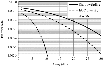
In order to improve the BER performance, a spatial diversity technique is also employed in the receiver. The diversity chooses two from the seven receivers placed around the human body as shown in Figure 4.11. The diversity combination adopts the EGC for simplicity because it does not need a phase detector and a shifter. The combined signal with EGC diversity over two log-normal distributed channels is approximated as a log-normal distribution. The MGF method, which matches a short Gauss–Hermite approximation of the MGF of the log-normal sum with that of a log-normal distribution, is then used to derive the PDF of the combined signal. Table 6.9 gives the two parameters μ and σ for two single received signal powers at Rx1 and Rx2 and the EGC combined signal power. The parameter σ is reduced significantly by the EGC diversity.
Table 6.9 Parameters of the log-normal distribution.
| μ | σ | |
| Rx1 | 0 | 1.87 |
| Rx2 | 0 | 1.70 |
| Rx1 and Rx2 | −0.45 | 1.38 |
The PDF for Eb/N0 is the same as the received signal power except for a shift of the mean value. With the derived PDF, we can calculate the theoretical BER performance for diversity reception. The result is shown in Figure 6.32. Compared with a single branch, the EGC diversity with two branches effectively improves the BER performance by an order of 8 dB. For example, the EGC diversity receiver only needs an Eb/N0 of 18 dB to obtain an average BER of 0.001. Moreover, the diversity gain can also be confirmed as 2 from the BER curves in Figure 6.32.
6.4.2 Link Budget
In order to analyze the link budget for the MICS-band transmission for capsule endoscope application, we should first prescribe the maximum transmitting power. Since the MICS band allows a maximum transmitting power of 25 μW or −16 dBm, we here use this power level in the link budget analysis. However, from the point of view of biological safety, 20 mW or 13 dBm may be also acceptable since it will never induce an SAR in the human tissue >2 W/kg in any 10 g.
As described in Section 6.2, we use Equation 6.30 to obtain the received power under the maximum transmitting power, and Equation 6.31 to obtain the link SNR or Eb/N0. With BER = 0.001 as the predetermined BER threshold for a BPSK optimum receiver, we can obtain the required Eb/N0 to be 26 dB without diversity and 18 dB with two-branch EGC diversity.
Using assumed system parameters in Table 6.10, Figures 6.33 and 6.34 show the dependence of system margin on distance with data rates of 0.1, 1 and 10 Mbps for a conventional optimum receiver without diversity and with EGC diversity, respectively. It can be seen that, without diversity, the system only has a margin larger than 0 dB within a distance of 12 cm at 0.1 Mbps and 5 cm at 10 Mbps for the transmission from the digestive organs. This is obviously insufficient for a real time capsule endoscope application. With the use of 2-finger EGC diversity, the communication distance may be increased to be more than 17 cm at 0.1 Mbps but is still smaller than 8 cm at 10 Mbps at a system margin larger than 0 dB. At a data rate of 1 Mbps, a communication distance of 12 cm, which basically covers the entire range from the digestive organs to the body surface, is achieved to have a system margin larger than 0 dB by EGC diversity. This link budget result shows the feasibility for capsule endoscope transmission at a low data rate but the difficulty at a high data rate in the MICS band.
Figure 6.33 Dependence of system margin on distance for conventional BPSK correlation receiver
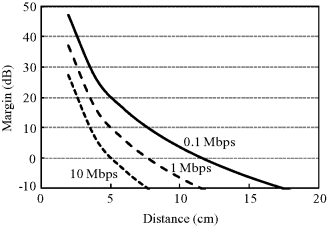
Figure 6.34 Dependence of system margin on distance for BPSK correlation receiver with EGC diversity
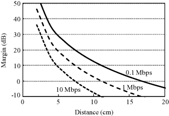
Table 6.10 Parameters for in-body MICS band link budget analysis.
| Transmitter and receiver | |
| Frequency (MHz) | 400 |
| Transmitter output power |
−16 |
| Transmitter antenna gain |
0 |
| Receiver antenna gain |
0 |
| Standard temperature T (K) | 300 |
| Receiver noise figure NF (dB) | 6 |
| Boltzmann constant k ([J/K) | 1.38E-23 |
| Signal quality | |
| Bite error rate | 10−3 |
| 26 (BPSK, correlation detection) | |
| 18 (BPSK, 2-finger EGC diversity) | |
| Coding gain (dB) | 0 |
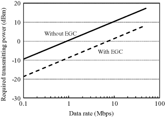
On the other hand, we can give the relationship between the data rate and required transmitting power for possible transmission at higher data rates. This relationship can be derived from Equation 6.33. Here Eb/N0 is set to be ![]() to obtain a BER of 0.001, that is, 26 dB without EGC diversity and 18 dB with 2-branch EGC diversity. Figure 6.35 shows the required transmitting power as a function of data rate at a communication distance of 15 cm. The result indicates the feasibility of a high data rate of 10 Mbps under a transmitting power below 0 dBm. Such a transmitting power level does not cause any biological thermal effect in the human body.
to obtain a BER of 0.001, that is, 26 dB without EGC diversity and 18 dB with 2-branch EGC diversity. Figure 6.35 shows the required transmitting power as a function of data rate at a communication distance of 15 cm. The result indicates the feasibility of a high data rate of 10 Mbps under a transmitting power below 0 dBm. Such a transmitting power level does not cause any biological thermal effect in the human body.
Figure 6.35 Required transmitting power versus data rate for in-body MICS band communication with a communication distance of 15 cm
6.5 Human Body Communication
HBC has an on-body path loss much smaller than that of UWB. Since the signal propagates mainly along the human body itself, the effect of human body posture is not so severe on the communication performance. In this section, with the same methodology as in the previous sections, we will derive the average BER performance using the HBC path loss model in Equation 4.34. We will also analyze the link budget based on the derived BER performances, and discuss the data rate versus required transmitting power.
6.5.1 Bit Error Rate
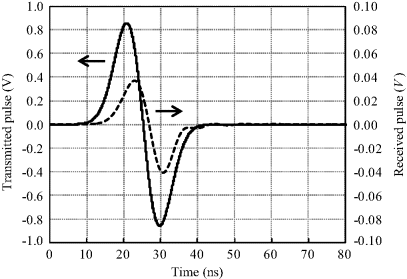
Figure 6.36 shows a typical example of transmitted and received pulse signals on the human body in the HBC band. Taking the correlation of the two signals we can get a correlation coefficient on the order of 0.9. This means that signal distortion is quite small due to the propagation characteristic of the human body except for an attenuation factor. In addition, the low data rate for HBC means no distinguishable multipath components exist. Thus the BER performance in a HBC channel is similar to that in an AWGN channel. For BPSK with correlation detection, the error probability is given as
Figure 6.36 Example of transmitted and received pulse signals on the human body in the HBC band
(6.34) ![]()
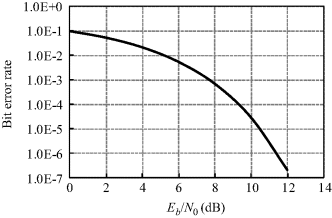
where ρ is the correlation coefficient between the transmitted and received signals. Figure 6.37 shows the calculated BER in a HBC channel with ρ = 0.9. The Eb/N0 versus BER performance is much better than that of on-body UWB. Only an Eb/N0 of 8 dB can provide a BER of 0.001.
Figure 6.37 BER performance in a HBC channel for BPSK correlation detection
6.5.2 Link Budget
As described in Section 6.4.2, since a transmitting power of 20 mW or 13 dBm will never induce an SAR in the human tissue >2 W/kg in any 10 g, we here use 13 dBm as the allowed maximum transmitting power in the link budget analysis. With BER = 0.001 as the predetermined BER threshold for a BPSK optimum receiver, we can obtain the required Eb/N0 to be 8 dB from Figure 6.37.
Table 6.11 gives the assumed system parameters for link budget analysis. It should be noted that HBC usually employs electrodes in the transmitter and receiver instead of antennas. The GTx and GRx in Table 6.11 are actually the gains for the transmitting and receiving electrodes. Since the electrode structure in the HBC band is difficult to have a 0 dB gain, we here assume a gain of −10 dB at both the transmitter and receiver. Figure 6.38 shows the dependence of system margin on distance with data rates of 0.1 and 1 Mbps, respectively. It can be seen that the system always has a margin larger than 0 dB for BER = 0.001 within a distance of 1.7 m for a data rate up to 1 Mbps. This link budget result demonstrates the feasibility of the on-body HBC link for covering the entire human body area.
Figure 6.38 Dependence of system margin on distance for on-body HBC communication with BPSK correlation detection
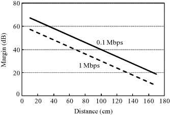
Table 6.11 Parameters for HBC band link budget analysis.
| Transmitter and receiver | |
| Frequency (MHz) | 10–50 |
| Transmitter output power |
13 |
| Transmitter electrode gain |
−10 |
| Receiver electrode gain |
−10 |
| Standard temperature T (K) | 300 |
| Receiver noise figure NF (dB) | 6 |
| Boltzmann constant k (J/K) | 1.38E-23 |
| Signal quality | |
| Bite error rate | 10−3 |
| 8 (BPSK, correlation detection) | |
| Coding gain (dB) | 0 |
On the other hand, we give the relationship between the data rate and required transmitting power for possible transmission at various data rates. This relationship can be derived from Equation 6.33 with the path-loss term replaced by Equation 4.34. Here ![]() is set to be
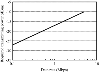
is set to be ![]() to obtain a BER of 0.001, that is, 8 dB. Figure 6.39 shows the required transmitting power as a function of data rate at an on-body communication distance of 1 m. The result indicates that a low transmitting power is usually sufficient for an on-body transmission with the HBC technique.
to obtain a BER of 0.001, that is, 8 dB. Figure 6.39 shows the required transmitting power as a function of data rate at an on-body communication distance of 1 m. The result indicates that a low transmitting power is usually sufficient for an on-body transmission with the HBC technique.
Figure 6.39 Required transmitting power versus data rate at an on-body HBC distance of 1 m
6.6 Dual Mode Body Area Communication
A BAN for healthcare and medical applications may need both on-body and in-body communication functions. The HBC band is a good candidate for on-body communication because the human body acts as a transmission medium in this frequency band. It is superior to the GHz band from the point of view of path loss and information security. A high security feature is also important in healthcare and medical BAN. On the other hand, in order to provide high-speed communication in implant BAN, the MICS band and UWB low band are promising candidates for in-body to on-body transmission. A dual model receiver structure can provide an effective network for both on-body and in-body BANs (Cho et al., 2009).
Figure 6.40 shows the concept of dual mode transmission. The on-body transceiver has both the HBC function and the in-body to on-body communication function. In order to have low power consumption, the design of the system requires a structure that is as simple as possible. Transmitting a very short pulse with no RF modulation, that is, the IR-UWB, uses a typically simple structure in which the information data symbols can modulate the pulses with the PPM scheme.
Figure 6.40 Concept of dual mode communication
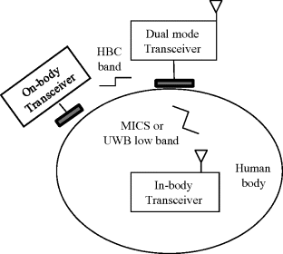
Figure 6.41 shows a block diagram for the realization of a dual model IR-UWB system. The pulses to be transmitted may be sinusoidally modulated Gaussian pulses as shown in Figure 6.42, which are generated by an oscillator and a band pass filter (BPF). The pulse widths are different for different modes: 50 ns for the on-body mode and 2.1 ns for the in-body mode. In the on-body mode, the oscillator generates a sinusoidal signal at 30 MHz, which is then passed through a Gaussian-shaped BPF to generate a pulse with a −10 dB bandwidth between 10 MHz and 50 MHz. On the other hand, in the in-body mode, the signal at 4.2 GHz is passed through a Gaussian-shaped BPF to produce a pulse with a −10 dB bandwidth between 3.4 GHz and 4.8 GHz. Figure 6.43 shows two examples of power spectra produced by the sinusoidally modulated Gaussian pulses in the on-body and in-body modes. They basically meet the above requirements. Since both of the two pulses meet the condition that the ratio of the bandwidth to the center frequency is larger than 0.2, they are the UWB signals. Using the two types of pulses, one for on-body and the other for in-body communication, the information data are modulated by PPM and then transmitted as pulse trains.
Figure 6.41 Block diagram for the realization of a dual model IR-UWB system
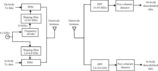
Figure 6.42 Sinusoidally modulated Gaussian pulses. The pulse widths are 50 ns for on-body mode and 2.1 ns for in-body mode
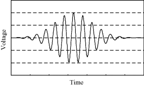
Figure 6.43 Normalized power spectra of the sinusoidally modulated Gaussian pulses (a) on-body mode; (b) in-body mode

For reception of the two mode signals, a common antenna/electrode structure is expected for system simplicity. After the antenna/electrode structure, the signals are sent to separate BPFs, and are then demodulated according to the mode. The dual mode design effectively meets the basic requirement for both on-body and in-body data rates in healthcare and medical applications. Its communication performance in each mode can be determined from the previous sections.
Benedetto, D.M.-G. and Giancola, G. (2004) Understanding Ultra Wide Band Radio Fundamentals, Prentice Hall, New Jersey, pp. 294–300.
Bic, J.C., Duponteil, D., and Imbeaux, J.C. (1991) Elements of Digital Communication, John Wiley & Sons Ltd., Chichester, pp. 462–467.
Cho, N., Roh, T., Bae, J., and Yoo, H.-J. (2009) A planar MICS band antenna combined with a body channel communication electrode for body sensor network. IEEE Transactions on Microwave Theory and Technique, 57 (10), 2515–2522.
FCC (2002) Federal Communications Commission: Revision of Part 15 of the Commission's rules Regarding Ultra-Wideband Transmission System: First report and order, Technical Report FCC 02–48 (Adopted February, 14 2002; Released April 22, 2002).
Shi, J., Anzai, D., and Wang, J. (2011) Performance analysis of diversity effect for in-body to on-body wireless UWB link. Proceedings of the 4th International Symposium on Applied Science in Biomedical and Communication Techniques, Barcelona, Spain.
Wang, J., Masami, K., and Wang, Q. (2011) Transmission performance of an in-body to off-body UWB communication link. IEICE Transactions on Communications, E93-B (4), 150–157.
Wang, Q. and Wang, J. (2010) Performance of ultra wideband on-body communication based on statistical channel model. IEICE Transactions on Communications, E93-B (4), 833–841.
