
The real world isn't digital. My digital-art-based vision shows me The Matrix behind things and huge digital waterfalls between things. In this chapter, however, I need to convey to you the relationship between digital and analog, and we need to understand it well.
This chapter is a good one but a huge one. Don't be afraid. We'll also discuss new concepts a lot while writing and designing pure C++ code.
We are going to describe together what analog inputs are. I'm also going to introduce you to a new and powerful friend worthy of respect, Max 6 framework. Indeed, it will help us a bit like Processing did—to communicate with the Arduino board. You'll realize how important this is for computers, especially when they have to sense the world. A computer with the Max 6 framework is very powerful, but a computer with the Max 6 framework and the Arduino plugin can feel much characteristics of the physical world, such as pressure, temperature, light, color, and many more. Arduino, as we have already seen, behaves a bit like a very powerful organ able to…feel.
If you like this concept of feeling things, and especially that of making other things react to these feelings, you'll love this chapter.
There's no better way to define analog than by comparing it to digital. We just talked about digital inputs in the previous chapter, and you now know well about the only two values those kind of inputs can read. It is a bit exhausting to write it, and I apologize because this is indeed more a processor constraint than a pure input limitation. By the way, the result is that a digital input can only provide 0 or 1 to our executed binary firmware.
Analog works totally differently. Indeed, analog inputs can continuously provide variable values by measuring voltage from 0 V to 5 V. It means a value of 1.4 V and another value of 4.9 V would be interpreted as totally different values. This is very different from a digital input that could interpret them as…1. Indeed, as we already saw, a voltage value greater than 0 is usually understood as 1 by digital inputs. 0 is understood as 0, but 1.4 would be understood as 1; this we can understand as HIGH, the ON value, as opposed to the OFF, which comes from the 0 V measure.
Here, in the continuous world of analog inputs, we can sense a flow between the different values, where digital inputs can provide only steps. This is one of the reasons why I'm always using the term "feeling". Yes, when you can measure a lot of values, this is near to sensing and feeling. This is a bit of humanization of the electronic hardware, and I totally assume that.
The term "a lot" isn't precise. Even if we are in a new continuous field of measure, we are still in the digital world, the one of the computers. So how many values can be distinguished by Arduino's analog inputs? 1024.
Why 1024? The reason is easy to understand if you understand how Arduino can feel continuous values.
Because Arduino's chip works in the digital domain for all calculations, we have to convert analog values from 0 V to 5 V to a digital one. The purpose of the analog-to-digital converter , housed within the chipset itself, is exactly this. This device is also referred to using the acronym ADC.
Arduino's ADCs have a 10-bit resolution. This means that every analog value is encoded and mapped to a 10-bit, encoded integer value. The maximum number encodable using this encoding system is 1111111111 in the binary system, which means 1023 in the decimal system. If I consider the first number to be 0, we have a total of 1024 values represented. A 1024-value resolution provides a very comfortable field of sensing as we are going to see in the next few pages.
Let's see how we can use these precious inputs with Arduino.
Because we are now more familiar with circuits and code, we can work with a small project while still explaining concepts. I'm going to describe a simple example of circuits and code using a potentiometer only.
First, let's grab a potentiometer. A potentiometer is, if you remember correctly from the first chapter of this book, a variable resistor.
Considering Ohm's law, which links voltage, current, and resistance value, we can understand that, for a constant current, we can make the voltage vary by changing the value of the resistance of the potentiometer. Indeed, because some of us haven't dusted off our elementary electronics course textbook in many years, how about a refresher? Here's Ohm's law:
V = R * I
Here, V is the voltage in Volts, R the resistance in Ohms, and I the current in Amperes.
So now, to define the purpose of a potentiometer:
The following figure is the most basic circuit to illustrate the concept of analog inputs with the Arduino board:
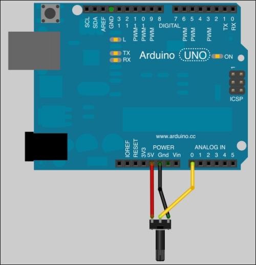
A potentiometer connected to the Arduino board
Check the corresponding electrical diagram for connections:
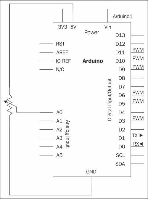
Analog input 0 is measuring the voltage
Now let's see the code we have to use.
Like the function digitalRead(), which can read the value of digital inputs on the Arduino, there is analogRead() for doing the same with analog inputs.
The intention here is to read the value as a pause value in our program for the purpose of controlling the blink rate of an LED. In code, we'll be using the delay() function.
Here's an example:
int potPin = 0;     // pin number where the potentiometer is connected
int ledPin = 13 ;   // pin number of the on-board LED
int potValue = 0 ;  // variable storing the voltage value measured at potPin pin

void setup() {
  pinMode(ledPin, OUTPUT);  // define ledPin pin as an output
}

void loop(){
  potValue = analogRead(potPin); // read and store the read value at potPin pin

  digitalWrite(ledPin, HIGH);    // turn on the LED
  delay(potValue);               // pause the program during potValue millisecond
  digitalWrite(ledPin, LOW);     // turn off the LED
  delay(potValue);               // pause the program during potValue millisecond
}
Upload the code. Then turn the pot a bit, and observe the output.
After the variable definition, I'm defining the ledPin pin as output in the setup() function in order to be able to drive current to this pin. Actually, I'm using pin 13 in order to simplify our tests. Don't forget pin 13 is the surface-mounted LED on the Arduino board.
Then, the magic happens in the loop() function.
I'm first reading the value at the potPin pin. As we discussed before, the value returned by this function is an integer between 0 and 1023. I'm storing it in the potValue variable to keep the LED ON, but also to keep it OFF.
Then, I'm turning OFF and ON the LED with some delay between status changes. The smart thing here is to use potValue as the delay. Turned on one side completely, the potentiometer provides a value of 0. Turned on the other side completely, it provides 1023, which is a reasonable and user-friendly delay value in milliseconds.
The higher the value is, the longer the delay.
In order to be sure you understood the physical part of this, I'd like to explain a bit more about voltage.
The +5 V and ground pins of the Arduino supply the potentiometer the voltage. Its third leg provides a way to vary the voltage by varying the resistance. The Arduino's analog inputs are able to read this voltage. Please notice that analog pins on the Arduino are inputs only. This is also why, with analog pins, we don't have to worry about precision in the code like we have for digital pins.
So let's modify the code a bit in order to read a voltage value.
Measuring voltage requires two different points on a circuit. Indeed, a voltage is an electrical potential. Here, we have (only) that analog pin involved in our circuit to measure voltage. What's that ?!
Simple! We're using the +5 V supply from Vcc as a reference. We control the resistance provided by the potentiometer and supply the voltage from the Vcc pin to have something to demonstrate.
If we want to use it as a real potentiometer, we have to supply another part of a circuit with Vcc too, and then connect our A0 pin to another point of the circuit.
As we saw, the analogRead() function only provides integers from 0 to 1023. How can we have real electrical measures displayed somewhere?
Here's how it works:
The range 0 to 1023 is mapped to 0 to 5V. That comes built into the Arduino. We can then calculate the voltage as follows:
V = 5 * (analogRead() value / 1023)
Let's implement it and display it on our computer by using the serial monitor of the Arduino IDE:
int potPin = 0;     // pin number where the potentiometer is connected
int ledPin = 13 ;   // pin number of the on-board LED
int potValue = 0 ;  // variable storing the voltage value measured at potPin pin
float voltageValue = 0.; // variable storing the voltage calculated

void setup() {
  Serial.begin(9600);
  pinMode(ledPin, OUTPUT);  // define ledPin pin as an output
}

void loop(){
  potValue = analogRead(potPin); // read and store the read value at potPin pin

  digitalWrite(ledPin, HIGH);    // turn on the LED
  delay(potValue);               // pause the program during potValue millisecond
  digitalWrite(ledPin, LOW);     // turn off the LED
  delay(potValue);               // pause the program during potValue millisecond

  voltageValue = 5. * (potValue / 1023.) ;  // calculate the voltage

  Serial.println(voltageValue); // write the voltage value an a carriage return
}
The code is almost the same as the previous code.
I added a variable to store the calculated voltage. I also added the serial communication stuff, which you see all the time: Serial.begin(9600) to instantiate the serial communication and Serial.println() to write the current calculated voltage value to the serial communication port, followed by a carriage return.
In order to see a result on your computer, you have to turn on the serial monitor, of course. Then, you can read the voltage values.
Please note that we are using an ADC here in order to convert an analog value to digital; then, we are making a small calculation on that digital value in order to have a voltage value. This is a very expensive method compared to a basic analog voltage controller.
It means our precision depends on the ADC itself, which has a resolution of 10 bits. It means we can only have 1024 values between 0 V and 5 V. 5 divided by 1024 equals 0.00488, which is approximated.
It basically means we won't be able to distinguish between values such as 2.01 V and 2.01487 V, for instance. However, it should be precise enough for the purposes of our learning.
Again, it was an example because I wanted to point out to you the precision/resolution concept. You have to know and consider it. It will prove very important and could deliver strange results in some cases. At least, you have been warned.
Let's discover another neat way of interacting with the Arduino board.