
In this chapter, we are going to learn different techniques that can be used either together or independently. Each technique developed here is a new tool for your future or current projects. We are going to use EEPROMs to provide Arduino boards with a small memory system that is readable and writable.
We are also going to test communications between the Arduino boards themselves, use GPS modules, make our boards autonomous, and more.
Until now, we learned and used the Arduino boards as totally electricity dependent devices. Indeed, they need current in order to execute tasks compiled in our firmware.
As we noticed, when we switch them off, every living variable and data is lost. Fortunately, the firmware isn't.
The Arduino boards based on the ATmega168 chipset own three different pools of memory:
- Flash memory
- SRAM
- EEPROM
The flash memory is also named program space. This is the place where our firmware is stored.
The SRAM stands for Static Random Access Memory and is the place where the running firmware stores, reads, and manipulates variables.
The EEPROM stands for Electrically Erasable Programmable Read-Only Memory. It is the place where we, programmers, can store things for long-term purposes. This is the place where our firmware sits, and anything in the EEPROM isn't erased should the board be switched off.
- 16000 bytes of Flash (2000 bytes are used for the bootloader)
- 1024 bytes of SRAM
- 512 bytes of EEPROM
Here we won't discuss the fact that we have to take care of the memory while programming; we will do that in the last chapter of this book Chapter 13, Improving your C Programming and Creating Libraries.
The interesting part here is the EEPROM space. It allows us to store data on the Arduino and we didn't even know that until now. Let's test the EEPROM native library.
Basically, this example doesn't require any wiring. We are going to use the internal EEPROM of 512 bytes. Here is some code that reads all the bytes of the EEPROM and prints it to the computer's Serial Monitor:
#include <EEPROM.h>

// start reading from the first byte (address 0) of the EEPROM
int address = 0;
byte value;

void setup()
{
  // initialize serial and wait for port to open:
  Serial.begin(9600);
}

void loop()
{
  // read a byte from the current address of the EEPROM
  value = EEPROM.read(address);

  Serial.print(address);
  Serial.print("	");
  Serial.print(value, DEC);
  Serial.println();

  // advance to the next address of the EEPROM
  address = address + 1;

  // there are only 512 bytes of EEPROM, from 0 to 511, so if we're
  // on address 512, wrap around to address 0
  if (address == 512)
    address = 0;

  delay(500);
}
This code is in the public domain and provided as an example for the EEPROM library. You can find it in your examples folder in the File menu of the Arduino IDE, under the folder Examples | EEPROM.
At first, we include the library itself. Then we define a variable for storing the current read address. We initialize it at 0, the beginning of the memory register. We also define a variable as a byte type.
In the setup() function, we initialize the serial communication. In loop(), we read the byte at the current address and store it in the variable value. Then we print the result to the serial port. Notice the value in the second Serial.print() statement. This stands for tabulation (as in the Tab key on a computer keyboard). This writes tabulation to the serial port between the current address printed and the value itself in order to make things more readable.
We advance to the next address. We check if the address equals 512, if that is the case, we restart the address counter to 0 and so on.
We add a small delay. We can write bytes in the same way using EEPROM.write(addr, val); where addr is the address where you want to write the value val.
Be careful, these are bytes (8 bits = 256 possible values). Read and write operations are quite easy on the internal EEPROM, so let's see how it goes with external EEPROMs wired by an I2C connection.
There are a lot of cheap EEPROM components available in electronics markets. We are going to use the classic 24LC256, an EEPROM implementing I2C for read/write operations and providing 256 kilobits (32 kilobytes) of memory space.
You can find it at Sparkfun: https://www.sparkfun.com/products/525. Here is how we can wire its bigger cousin 24LC1025 (1024k bytes) using I2C:
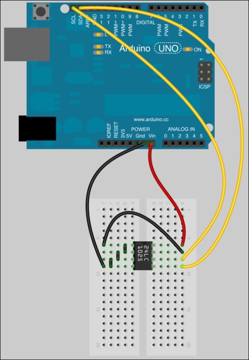
A 24LC256 EEPROM wired to the Arduino via I2C communication
The corresponding diagram is the one shown as follows:
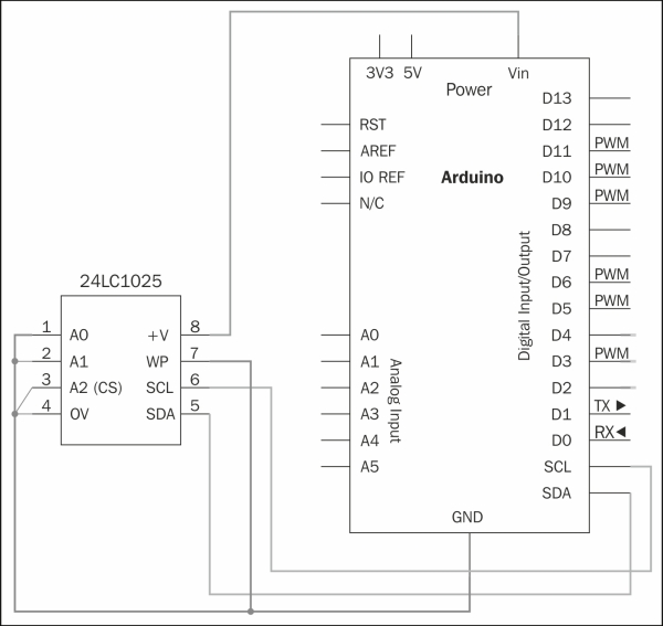
A 24LC256 EEPROM wired to the Arduino via I2C communication
A0, A1, and A2 are chip address inputs. +V and 0V are 5V and ground. WP is the write protect pin. If it is wired to ground, we can write to the EEPROM. If it is wired to 5V, we cannot.
SCL and SDA are the two wires involved in the I2C communication and are wired to SDA / SCL. SDA stands for Serial Data Line and SCL stands for Serial Clock Line. Be careful about the SDA/SCL pins. The following depends on your board:
The underlying library that we can use for I2C purposes is Wire. You can find it directly in the Arduino core. This library takes care of the raw bits, but we have to look at it more closely.
The Wire library takes care of many things for us. Let's check the code in the folder Chapter10/readWriteI2C:
#include <Wire.h>

void eepromWrite(byte address, byte source_addr, byte data) {
  Wire.beginTransmission(address);
  Wire.write(source_addr);
  Wire.write(data);
  Wire.endTransmission();
}

byte eepromRead(int address, int source_addr) {
  Wire.beginTransmission(address);
  Wire.write(source_addr);
  Wire.endTransmission();

  Wire.requestFrom(address, 1);
  if(Wire.available())
    return Wire.read();
  else
    return 0xFF;
}

void setup() {
  Wire.begin();
  Serial.begin(9600);

  for(int i = 0; i < 10; i++) {
    eepromWrite(B01010000, i, 'a'+i);
    delay(100);
  }

  Serial.println("Bytes written to external EEPROM !");
}

void loop() {
  for(int i = 0; i < 10; i++) {
    byte val = eepromRead(B01010000, i);
    Serial.print(i);
    Serial.print("	");
    Serial.print(val);
    Serial.print("
");
    delay(1000);
  }
}
We include the Wire library at first. Then we define 2 functions:
These functions write and read bytes to and from the external EEPROM using the Wire library.
The Setup() function instantiates the Wire and the Serial communication. Then using a for loop, we write data to a specific address. This data is basically a character 'a' plus a number. This structure writes characters from a to a + 9 which means 'j'. This is an example to show how we can store things quickly, but of course we could have written more meaningful data.
We then print a message to the Serial Monitor in order to tell the user that Arduino has finished writing to the EEPROM.
In the loop() function, we then read the EEPROM. It is quite similar to the EEPROM library.
Obviously, we still haven't spoken about addresses. Here is an I2C message format:
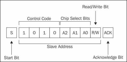
An I2C message
Wire library takes care of Start Bit and Acknowledge Bit. The control code is fixed and you can change the Chip Select Bits by wiring A0, A1, and A2 pins to ground or +V. That means there are 8 possibilities of addresses from 0 to 7.
1010000 1010001… until 1010111. 1010000 binary means 0x50 in hexadecimal, and 1010111 means 0x57.
In our case, we wired A0, A1, and A2 to ground, then the EEPROM address on the I2C bus is 0x50. We could use more than one on the I2C bus, but only if we need more storage capacity. Indeed, we would have to address the different devices inside our firmware.
We could now imagine storing many things on that EEPROM space, from samples for playing PCM audio to, eventually, huge lookup tables or whatever requiring more memory than available on Arduino itself.