Chapter 2
Cloud Fundamentals
In this chapter, you will learn the following:
It’s a multicloud world, where organizations are leveraging cloud computing services from multiple cloud providers. Cloud services are available on demand, are scalable, and can be accessed from anywhere. They allow organizations to focus their IT resources on strategic innovations such as high-end business application development, business analytics, new business models, and applications to enhance the productivity of employees as well as the customer experience. With the use of cloud, expenses move from data center infrastructure costs in hardware and software to costs based on the usage of compute resources, and this shift dramatically reduces costs.
Cloud Fundamentals
Before we explain the fundamental concepts of cloud computing, you need to understand the following terminology to be able to quickly grasp the concepts explained in this chapter:
Abstraction: To reduce or hide details to make something easier to understand. For example, the cloud hides or abstracts all the underlying hardware and software components that comprise it.
Server: A server is a specialized computer, either physical or virtual, that is used to host server programs that can accept and process requests from clients. Some examples of the most typical servers include web servers, application servers, database servers, email servers, and file servers.
Tenant: A logical application container that requires isolation from other tenants or the outside world. A tenant can be an application, an organization, a business unit, a single department, and so on.
Bare-metal server: This simply refers to a physical server that is dedicated to a single tenant (in other words, not shared with other tenants).
Virtualization: Virtualization is the process of using software on a computer or physical server that allows multiple operating systems to run on virtual machines (VMs) on a single computer. A bare-metal server, for example, can only operate with one operating system (OS) at a time, whereas a server running virtualization software (VMware, Hyper-V, and so on) can be used to run multiple VM instances at the same time, each with independent OS configurations.
Multitenant: A software architecture in which a single server or computing environment is shared but logically isolated to serve multiple tenants.
Databases: An organized collection of data that that can be efficiently queried, managed, and updated by other applications (for example, SQL).
Middleware: Anything that is not part of an OS and not part of a software application, but rather lies in between. Therefore, a web server, for example, qualifies as middleware because it is not part of the OS and it’s not the actual application.
Workload: A workload is an abstraction of the amount of work or processing required by a software program, and if applicable, the number of incoming connections from clients interacting with the software program. In cloud terms, a workload usually refers to one of the following components:
Virtual machine
Container
Container pod
Application
Middleware (that is, a web server)
Database
Service
On-premises (on-prem): This simply refers to a location that belongs to the customer. For example, a traditional IT data center would be an on-prem data center.
As a Service (aaS): This means services are delivered through software from the cloud.
The National Institute of Standards and Technology (NIST) defines cloud as “a model for enabling ubiquitous, convenient, on-demand network access to a shared pool of configurable computing resources (e.g., networks, servers, storage, applications, and services) that can be rapidly provisioned and released with minimal management effort or service provider interaction.”
In addition, it mentions that a cloud environment is composed of five essential characteristics, three service models, and four deployment models, as shown in Figure 2-1.

Essential Characteristics
The following are five essential characteristics as defined by NIST that all cloud services should offer. If any of them is lacking, it is likely not a cloud service.
On-demand self-service: This means end users have access to a portal where they can directly request computing resources from the cloud. Deployment will be completely automatic without the need for any human interaction with the cloud service provider (CSP).
Measured service: Just like with a water or power bill, you may be charged for cloud resources such as CPU, storage, and bandwidth, depending on how much you use them. There are some CSPs that offer free basic services, and for additional premium capabilities a paid subscription is required (for example, Dropbox, Box, and Lucidchart).
Rapid elasticity: This means the cloud should be able to automatically scale up/out and scale down/in based on service utilization. When a consumer requests changes through a portal to increase or decrease the amount of computing resources needed, the changes should happen automatically in the cloud.
Resource pooling: The CSP should have a pool of resources that can be shared among different consumers or tenants. This means that the CSP should support multitenancy and that the resources used by the tenants are shared. When a tenant stops using a resource, it can be decommissioned, put back into the pool of resources, and become available for other tenants to consume. This can be achieved by using orchestration and automation tools.
Broad network access: This is the ability to reach the cloud from anywhere using mobile phones, tablets, laptops, workstations, and so on.
Note
One big difference between cloud computing and traditional virtualization is that although virtualization can abstract resources from the underlying physical infrastructure, it lacks the orchestration to pool them together and deliver them to consumers on demand and without manual intervention.
Service Models
The following sections describe the different cloud service models available today.
Infrastructure as a Service (IaaS)
Figure 2-2 illustrates that with IaaS, the service provided to the customer is virtualization, servers (compute capacity), storage, networking, and other fundamental computing resources where the customer is able to deploy and run any OS, middleware, and applications. The customer does not manage or control the underlying cloud infrastructure but has control over operating systems, storage, and deployed applications. The cloud service providers may also include limited control of networking components (such as a virtual switch).

This type of service model is great for IT departments because it allows them to migrate their on-prem applications easily into the cloud.
Some examples of IaaS services include the following:
Amazon Web Services (AWS) Elastic Compute Service (EC2)
Google Compute Engine
Microsoft Azure IaaS
IBM Bluemix
Platform as a Service (PaaS)
This is very similar to IaaS; the only difference, as illustrated by Figure 2-3, is that PaaS also provides the OS as well as development application platforms (that is, the ability to run PHP, Python, or other programming languages), databases, file storage, collaboration, machine learning, big data processing, and so on. The consumer can deploy third-party applications supported by the CSP or they can develop their own application in the cloud without the worrying about the complexities of managing the underlying infrastructure services.

This type of service model is ideal for developers because they don’t have to worry about having to install a database or any middleware. With a PaaS service model, all of this is included and there is no need to manage the underlying servers, networks, or other infrastructure. All that needs to be provided is the application and the application data.
Some examples of PaaS services include the following:
AWS Elastic BeanStalk
Google App Engine
Microsoft Azure
IBM Bluemix
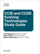
Software as a Service (SaaS)
In this type of service model, everything is provided by the cloud service provider except the application data, as illustrated in Figure 2-4. This is the type of service that everyone uses on a daily basis; for example, web-based email (such as Gmail), Dropbox, Facebook, and so on, are all SaaS services.
Some examples of SaaS services include the following:
Salesforce.com
SAP Business by Design
Oracle on Demand
Office365
Cisco Webex
Box
XaaS (Everything as a Service)
This can be seen as a combination of IaaS, PaaS, and SaaS where everything can be a service. Here are some examples:
Desktop as a Service
Backup as a Service
Database as a Service
Security as a Service
IP Telephony as a Service
Disaster Recovery as a Service
Monitoring as a Service
VPN as a Service
Analytics as a Service
Cloud Deployment Models
The following sections describe the different cloud deployment models.
Public Cloud
For this type of cloud deployment model, the cloud infrastructure is available to the general public over the Internet. This type of cloud is owned, managed, and operated by the CSP. Some examples include the following:
Amazon Web Services (AWS)
AWS GovCloud
Oracle Cloud
Google Cloud Platform (GCP)
Microsoft Azure
Microsoft Azure Government
IBM Cloud
Alibaba Cloud
Private Cloud
The cloud infrastructure is provisioned for exclusive use by a single organization. It may be owned, managed, and operated by the organization, a third party, or a combination of the two, and it may exist on or off premises.
Here are some examples of on-prem private clouds:
OpenStack
Microsoft Azure Stack
VMware vCloud Suite Private Cloud
Cloud providers can also emulate a private cloud within a public cloud environment (think of it as a cloud within a cloud). Amazon Web Services and Google Cloud Platform call this type of private cloud a Virtual Private Cloud (VPC), whereas Microsoft Azure calls it a Virtual Network (VNet).
A VPC or VNet isolates resources for a cloud tenant from other tenants through a private IP subnet and a virtual network segment defined by the user.
Community Cloud
A community cloud is a private cloud that serves a group of organizations that have shared common interests such as mission objectives, security, privacy, and compliance policies and standards. Similar to a private cloud, a community cloud may be owned, managed, and operated by the organizations or by a third party, and it may exist on premises (that is, an on-site community cloud) or off premises (that is, an outsourced community cloud).
Community clouds are very common for the public sector or the government because they require regulatory standards that will be described later in this chapter in the “Security Implications, Compliance, and Policy” section.
Examples of community clouds include the following:
AWS GovCloud
Google Apps for Government
Microsoft Government Community Cloud
Salesforce Community Cloud
Capital Markets Community Platform (NYSE)
Healthcare Community Cloud (Carpathia)
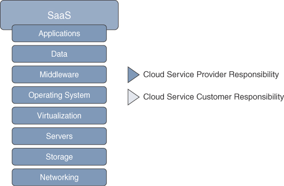
Hybrid Cloud
Figure 2-5 illustrates a hybrid cloud, which is when a private cloud and a public cloud combine and are bound together by standardized or proprietary technology that enables data and application portability (that is, cloud bursting for load balancing between clouds).
Examples of hybrid cloud solutions include the following:
Cisco and Google Cloud Hybrid Cloud Solution
Microsoft’s Hybrid Cloud Platform with Microsoft Azure Stack
Terremark CloudSwitch
IBM Hybrid Cloud Solution
Rackspace Hybrid Cloud
Fujitsu Hybrid Cloud Services
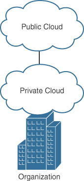
Multicloud
A multicloud (not defined by NIST) enables customers to consume applications and services from two or more clouds, where at least one cloud is public. To understand the difference between multicloud and hybrid cloud, let’s compare them from the networking standpoint:
Multicloud networking: Network transport is from private cloud to multiple public cloud providers and/or between multiple public cloud providers (where supported) and/or between multiple private clouds (including vNETs/VPCs). This is illustrated in Figure 2-6.
Figure 2-6 Multicloud Deployment Model Hybrid cloud networking: Network transport is from private cloud to a single public cloud provider. In other words, hybrid clouds are a subset of multicloud.
The following are some of the benefits from adopting a multicloud solution:
CSP high availability
More options for regional cloud provider access
The ability to overcome feature disparity between CSPs, regions, and/or services (machine learning, tooling, security regulations, and so on)
No CSP lock-in
Performance, Scalability, and High Availability
Performance, scalability, and high availability are commonly used interchangeably, because to a certain degree, they can affect each other, but they are not exactly the same thing.
For example, application performance indicates how fast an application can execute an action within a time interval, whereas scalability would be a system’s ability to handle an increase in demand without impacting the application’s performance. If the increase in demand is too large to handle and resources are not available to keep up with the demand, this would have an impact in application performance that would cause the application to become sluggish, unresponsive, or to crash. This is where high availability comes in, which can be achieved by scaling (up or out) the resources or seamlessly failing over to another system while the application remains available and accessible without any noticeable interruption. For a system to have true high availability, it not only needs to be always on but must also provide a service level agreement (SLA) of at least 99% of uptime/availability.
Application Scalability and Elasticity
Scalability can either be vertical (scale-up), by adding more resources to a system (memory, CPU, storage, bandwidth, and so on), or horizontal (scale-out), by adding more systems (that is, by means of clustering or load balancing). This way, applications can either scale up or scale out to prevent a lack of resources from affecting performance or availability. But there is more to just scaling up or scaling out; what if the demand decreases and you end up with an overprovisioned system? That’s where cloud elasticity comes in, which is the ability to increase (scale out/up) or decrease (scale in/down) resources to meet changing demand without overprovisioning capacity.
Elasticity is typically referred to as auto-scaling by CSPs. Some examples of these services include the following:
AWS Auto Scaling
Microsoft Azure Autoscale
Google Cloud Platform Autoscaling
Elasticity can give the illusion of infinite cloud resources while addressing performance, scalability, and high availability concerns.
Application Performance with WAN Optimization
One key factor that can have an impact in application performance is that most traditional applications do not take the network characteristics into account and typically rely on protocols like TCP for communicating between different systems. Traditional IT applications tend to be chatty and are usually designed for LAN environments that can provide high-speed bandwidth and are not easily congested. When an application resides across a WAN, most users assume the application responsiveness or performance is directly related to the available bandwidth on the WAN link. While bandwidth is one of the factors that can affect application performance, there are other factors that can also affect performance, such as path latency, congestion, and application behavior.
When those applications are migrated to the cloud, they are typically accessed across the WAN from branch locations. To make sure the application performance is not affected, consistent, high-quality performance with maximum reliability and minimum latency is required on the WAN link, and this can be achieved with WAN optimization.
Cisco Wide Area Application Service (WAAS) and Akamai Connect technologies provide a complete WAN optimization and application acceleration solution for overcoming WAN performance issues that can have a direct negative impact on application performance, which consequently affects end-user productivity. They are transparent to the endpoints (clients and servers) as well as devices between the WAAS/Akamai Connect devices.
Cisco WAAS incorporates data redundancy elimination (DRE) technology to identify repeating data elements or patterns in network traffic. When repeating data patterns are detected, they are simply replaced by simple pointers or references so that the long data patterns do not have to repeated multiple times in their entirety. This drastically reduces the size of the packet as it crosses the WAN, and at the same time keeps the original payload between the communicating devices.
Cisco WAAS and Akamai Connect also provide a method of caching objects locally. Caching repeat content locally shrinks the path between two devices and can reduce latency on chatty applications. For example, suppose the latency between a branch desktop and the local object cache (WAAS/Akamai Connect) is 10ms, and it takes 100ms to retrieve a file from the cloud. Only the initial file transfer would take the 100ms delay, and subsequent requests for the same file are provided locally from the cache with a 5ms response time.
Application Performance with Quality of Service
Quality of Service (QoS) should also be implemented in conjunction with WAN optimization to improve application performance. Business-critical or latency-sensitive applications residing in the cloud should be classified as high priority and given enough WAN link queue bandwidth so they can continue to work optimally in case of WAN link congestion.
A detailed discussion of QoS is outside the scope of this book. Further information on QoS deployment can be found in the Cisco Press publication End-to-End QoS Network Design: Quality of Service for Rich-Media & Cloud Networks, Second Edition, by Tim Szigeti, Christina Hattingh, Robert Barton, and Kenneth Briley.
Performance Routing
Performance Routing (PfR) is another feature that can be used to optimize application performance by providing dynamic selection of the best WAN link for applications based on a traffic class policy (delay, loss, and jitter measurements). It can also perform application-based load balancing across multiple WAN links, allowing for maximum utilization of bandwidth and high availability.
Application Performance Monitoring and Management
Application performance management (APM) is critical in dynamic cloud environments where components and services are continuously being added and removed. The purpose of APM is to predict, detect, and diagnose complex application performance problems to ensure optimal cloud computing services. Following are some of the key benefits developers can obtain from using APM tools or suites to improve the quality and performance of their software and to ensure an optimal end-user digital experience:
Visualize application performance in real time.
Capability to troubleshoot problems such as slow response times and application errors.
Automatically discover application topology and how the different components in the application environment work together to fulfill key business transactions for its users.
Measure end-to-end business transaction performance (that is, capability to measure end-to-end performance of paying with a chip card), along with the health of individual application and infrastructure nodes.
Receive alerts based on custom or built-in health rules, including rules against dynamic performance baselines for issues in the context of business transactions.
Provides end-to-end visibility of web and mobile application performance.
Helps developers troubleshoot problems such as slow web applications, mobile network requests, and IoT application errors.
Automatically captures errors, crashes, network requests, page-loading details, and other metrics covering an entire user session.
Identify front-end issues faster and understand how third-party APIs and content services affect the app and web performance.
Get traceability from front-end to back-end application dependencies.
Gartner’s 2018 “Magic Quadrant for Application Performance Monitoring Suites” publication positions New Relic, Dynatrace, and Cisco’s AppDynamics as the three leading APM suites.
Application Performance with DNA Center
Another option to aid in application performance is to use Cisco’s Digital Network Architecture (DNA) Center. Cisco’s DNA Center is a controller and analytic platform that includes service assurance capabilities and has rich contextual visibility into the user-to-application experience; in other words, it includes historical, real-time, and predictive insights across users, devices, applications, and the network. It can also send notifications in case of any service-impacting network issues that require proactive attention and suggests remediation before end users notice them themselves.
Application Scalability with Cloud Bursting
Cloud bursting is a way to scale out a private cloud into a public cloud whenever there is an increase in demand that goes above a specified threshold. When the demand decreases, the public cloud resources are released. Another way to look at cloud bursting is as elasticity in a multicloud environment that allows scaling out and in between cloud providers.
A good use case for cloud bursting would be retail; for example, if a good volume of sales is expected during the holiday season, more resources from the private cloud could be required during that time. If the private cloud does not have enough resources to cope with the increase in service demands, it can then burst into the public cloud, leveraging extra capacity as required, and when the resources are not needed, they can be released and the consumer can just pay for the resources that were used.
For this type of cloud, an orchestrator/management solution is required to know when to leverage the private cloud and when to use resources from the public cloud and how to merge and connect the control processes between the two. Security and compliance requirements, latency, load balancing, and platform compatibility should also be considered.
Application High Availability
Cloud providers offer service level agreements (SLAs) in which they indicate the monthly uptime percentage of availability/uptime for their services. For example, at the time of writing, AWS EC2, Google Cloud Platform, and Microsoft Azure all offer 99.99% availability/uptime, and if they do not meet the agreement, they all offer financial credit that varies, depending on the severity of the downtime and other stipulations in their SLAs. In other words, 99.99% availability/uptime essentially implies that AWS, Google, and Microsoft Azure can go down every day for 8.6 seconds (or no more than once a year for 52 minutes and 37.7 seconds). If the downtime goes beyond this, then the cloud consumer is eligible for financial credit.
If an application requires more than 99.99% availability (for example, 99.999%), then a multicloud solution is what’s needed. Applications can then be hosted and replicated to multiple providers to greatly reduce the chances of failure.
Security Implications, Compliance, and Policy
Cloud security is more than just securing the cloud; it is also about the new security implications that come with the shift in how the networks and endpoints access data and applications. Organizations accessing data and applications in the cloud have shared risks and responsibilities with the CSPs that vary depending on which type of cloud service model is in use.
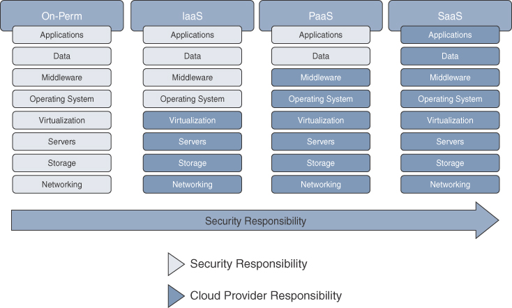
The cloud service models (IaaS, PaaS, and SaaS) can be thought of as stacks, where IaaS is at the bottom of the stack, with PaaS in the middle and SaaS at the top. In this stack, the security responsibilities are shared between the cloud customer and the CSP, where at the bottom of the stack the consumer has the most responsibility and, as you move further up the stack, the CSP has the most responsibility. In other words, security responsibilities in the cloud map to the degree of control that the cloud customer or CSP has over the service model; this is known as the shared responsibility model.
Figure 2-7 shows an example of the shared responsibility model where on the left side, the customer is mostly responsible, and higher up the stack, the CSP is mostly responsible.
Cloud Security Alliance’s “Security Guidance for Critical Areas of Focus in Cloud Computing v4.0” includes two recommendations that directly correlate with the shared responsibility model:
CSPs should properly design, implement, and document their security controls and customer features.
Cloud consumers should develop a responsibilities matrix to document how and who is implementing which security controls as well as any needed compliance standards.
The Cloud Security Alliance (CSA) provides two tools to help meet the recommended requirements:
The Consensus Assessments Initiative Questionnaire (CAIQ)
The Cloud Controls Matrix (CCM)
Industry Regulatory Compliance Guidance
With cloud computing environments, data can reside anywhere and services are delivered on demand to any endpoint. Public clouds allow organizations to reduce their IT infrastructure costs, as well as management costs, by storing data assets in a multitenant, but secured, cloud-hosted environment. Organizations can also build their own private clouds that can deliver cloud-based services to their own organization.
Regulatory compliance is an organization’s adherence to regulations, laws, guidelines, and specifications that are relevant to their business. Violations of compliance regulations often result in regulatory actions, such as federal fines or litigation.
There are different regulatory compliance laws for different verticals, such as the following:
Payment Card Industry Data Security Standard (PCI DSS): This is for companies that handle credit card information, and it serves to protect customer data in an attempt to reduce credit card fraud.
Federal Risk and Authorization Management Program (FedRAMP) and the Federal Information Security Management Act (FISMA) / NIST 800-53: These are for government agencies and their service providers. They assist in assessing and meeting FISMA requirements to attract government agency business moving to the cloud as part of FedRAMP.
Health Insurance Portability and Accountability Act (HIPAA) and Health Information Technology for Economic and Clinical Health (HITECH): These are for the healthcare segment, bringing multilocation medical centers and healthcare organizations into compliance.
International Organization for Standardization (ISO) 27001 (2013): Provides requirements for establishing, implementing, maintaining, and continuously improving an information security management system (ISMS).
ISO 27018 (2014): Code of practice for protection of personally identifiable information (PII) in public clouds acting as PII processors.
ISO 27017 (2015): Code of practice for information security controls based on ISO / International Electrotechnical Commission (IEC) 27002 for cloud services.
Service Organization Controls (SOC), SOC1 / SOC2: SOC 1 is the reporting option for which the Statement on Standards for Attestation Engagements (SSAE) 16 professional standard is used, resulting in a SOC 1 SSAE 16 Type 1 and/or a SOC 1 SSAE 16 Type 2 report. SOC 2 is the reporting option specifically designed for many of today’s cloud computing services, SaaS, and technology-related service organizations.
Independent parties need to perform periodic audits for most of these standards to validate an organization’s continuous compliance. Cloud environments and their security risks are taken into consideration in such audits.
Top Cloud Threats
The CSA Top Threats working group conducted a survey to compile industry expert professional opinions on the greatest security issues within cloud computing. With the survey results and their expertise, they crafted a report titled “The Treacherous 12—Top Threats to Cloud Computing in 2016.” Table 2-1 displays the 12 top threats included in the report. They are arranged based on order of severity, as per the survey results, where 1 is the highest severity.
Table 2-1 Cloud Computing Top Threats
Sev. |
Critical Issues |
Description |
Security Measures |
1 |
Data breaches |
A data breach is an incident in which protected, sensitive, or confidential information such as health records and financial records are released, viewed, stolen, or used by someone who is not authorized to do so. |
Multifactor authentication. Data encryption. Implement a data loss prevention (DLP) solution. Implement a cloud access security broker (CASB) solution. |
2 |
Insufficient identity, credential, and access management |
Data breaches typically occur because of a lack of proper identity access management systems and practices (for example, not using multifactor authentication or allowing users to set weak passwords). |
Multifactor authentication. Strong passwords. |
3 |
Insecure APIs |
Cloud computing providers expose application programming interfaces (APIs) that developers use to manage and interact with cloud services, and they are typically a target of heavy attacks. |
Use API keys instead of usernames and passwords and store the key in a safe place. Perform penetration testing. |
4 |
System and application vulnerabilities |
System vulnerabilities are exploitable weaknesses that are typically caused by bugs that attackers can use to infiltrate a computer system to steal data, take control of the system, or cause a denial of service. |
Regular vulnerability scanning. Quickly taking action on reported system threats. Installation of security patches or upgrades. |
5 |
Account hijacking |
This type of attack is typically achieved by using attack methods such as phishing and exploitation of system vulnerabilities. |
Prohibit sharing of credentials. Enforce strong two-factor authentication. Monitor accounts and activities. Install security patches or upgrades. Educate end users. |
6 |
Malicious insiders |
A malicious insider is an employee, contractor, partner, and so on, who has authorized access to internal confidential resources and then misuses those resources, negatively affecting the organization. |
Educate end users. Role-based access control (RBAC). Logging, monitoring, and auditing of administrator’s activities. |
7 |
Advanced persistent threats (APTs) |
APTs (aka malware) are a parasitical form of cyberattack that infiltrates the computing systems of target companies from which they smuggle data and intellectual property. |
Be up-to-date on latest advanced cybersecurity attacks. Educate users to recognize phishing and spear phishing, which are commonly used to introduce APTs. Use antimalware controls. |
8 |
Data loss |
An attacker gaining access to cloud resources could cause a massive permanent loss of data, which can put a company out of business (for example, by encrypting it with ransomware or deleting it). |
Implement a data loss prevention (DLP) solution. Implement mobile device management (MDM) techniques. Employ RBAC. Implement encrypted backups. |
9 |
Insufficient due diligence |
This is when an organization opens itself up for a large number of threats by adopting a cloud service from a CSP directly or via a merger without evaluating the CSP properly. |
Adhere to the guidelines described in CSA’s “Security Guidance for Critical Areas of Focus in Cloud Computing.” Use CSA’s CCM and CAIQ tools. |
10 |
Abuse and nefarious use of cloud services |
This includes using cloud services to launch DDoS attacks, email spam and phishing, digital currency mining, and hosting of malicious or pirated content. |
A CSP must have an incident response framework to address misuse of resources. |
11 |
Denial of service |
This is an attack that consumes an inordinate amount of cloud resources or targets a specific vulnerability to make the cloud service slow or completely unavailable to other cloud users. |
Employ distributed denial of service (DDoS) attack detection. Put in place a mitigation plan. Use multicloud. |
12 |
Shared technology vulnerabilities |
CSPs rely on multitenant environments. This can lead to shared technology vulnerabilities that can potentially be exploited in all delivery models. |
Multifactor authentication. Intrusion prevention system (IPS). |
Note
Keep in mind that these security issues are not unique to cloud computing and could happen in a traditional IT environment.
To make appropriate cloud security strategies, the CSA group recommends to use its threat research report in conjunction with the latest available versions of the following guides:
CSA Security Guidance for Critical Areas in Cloud Computing
CSA Security as a Service Implementation Guidance
NIST Risk Management Framework
Cloud Security
Cloud services provide reduced cost and efficiency gains for businesses as long as security policies, processes, and best practices are taken into account. If not, businesses are vulnerable to security data breaches or other threats, as mentioned earlier in this chapter, which can eliminate any benefits gained from switching to cloud technology.
A cloud security architecture should extend protection to all aspects of security across the endpoint, network, and cloud ecosystem, as illustrated in Figure 2-8, to stop threats before, during, and after attacks.
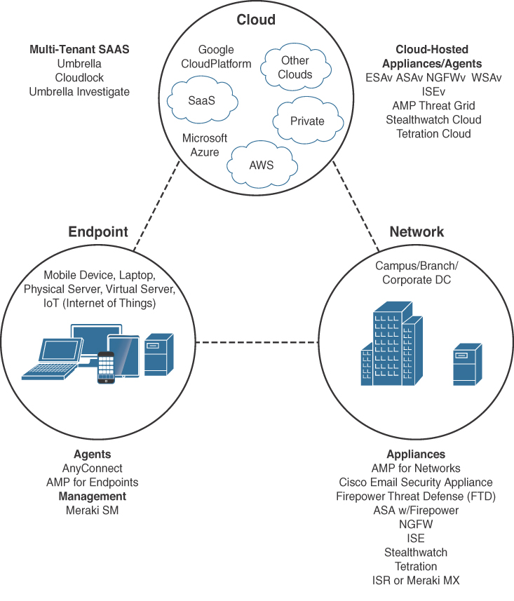
Table 2-2 includes only the most important Cisco security products shown in Figure 2-8. It covers their capabilities, the form factor, as well as which part of the security ecosystem they play a security role in.
Table 2-2 Cisco Security Products
Product |
Capability |
Operates In |
Form Factors |
Advanced Malware Protection (AMP) |
Antimalware, malware sandboxing |
Endpoint, network, cloud |
Endpoint Agent, NGIPS (AMP for Networks), Next-Generation Firewall, Meraki MX UTM platform, Branch router (ISR), cloud service |
AnyConnect |
Network Admission Control (NAC), virtual private network (VPN) |
Endpoint |
Endpoint agent |
Cloudlock |
User behavior analytics (UEBA), data security, DLP, cloud access security broker (CASB) |
Cloud |
Cloud service |
Cisco Email Security Appliance (ESA) |
Email security |
Network, cloud |
Physical or virtual appliance |
Firepower (NGFW, NGFWv) |
Firewall |
Network |
Physical or virtual appliance |
Firepower Threat Defense (FTD) |
IPS |
Network |
Physical or virtual appliance |
Cisco Identity Services Engine (ISE) |
NAC, context |
Network |
Physical or virtual appliance |
Stealthwatch |
Flow analytics |
Network |
Physical or virtual appliance |
Stealthwatch Cloud |
UEBA, flow analytics |
Cloud |
Cloud service |
Tetration |
Flow analytics |
Network, cloud |
Endpoint agent, cloud service |
Umbrella |
Domain name system (DNS) security, web security |
Cloud |
Cloud service |
Cisco Web Security Appliance (WSA, WSAv) |
Web security |
Network, cloud |
Physical or virtual appliance |
Workload Migration
Migrating applications into the cloud takes planning. Organizations need to do a discovery and an analysis of the applications in their environment to determine which applications are suitable for migration and which are not; for example, many applications were not developed to be portable or to work in a virtualization environment, and can only work in very specific environments that cannot be re-created in the cloud. They may have specialized hardware requirements, use legacy databases, or lack proper security.
There are also performance-intensive applications that are better suited to run on bare-metal servers (for example, trading applications where fast transactions dictate revenue). Furthermore, security compliance and regulations may keep certain applications from running in public clouds.
Other considerations need to be taken into account to determine whether or not an application or workload is suitable for a cloud environment. For example, applications or workloads suitable for cloud may include the following:
Applications that need significant compute resources (IoT, big data, analytics)
Applications that require bursting (rapid scaling of resources)
Collaboration applications (email, voice, messaging)
DevTest and development applications
Storage (file backups)
Examples of applications or workloads not suitable for cloud may include the following:
Applications that use extremely sensitive data
Applications that are sensitive to latency
Applications that run on specialized hardware
Applications that run on operating systems not supported by the cloud provider
Applications running frequent large-volume transactions with on-prem databases
Applications with too many dependencies on other applications that cannot be migrated
To migrate applications into the cloud, a migration methodology can be applied just as when migrating from an old infrastructure to a new one. The first step for the migration is to do an application discovery in the environment and categorize the applications in a matrix to determine whether or not they are suitable for migration. Here are some of the items to consider apart from the ones mentioned previously:
Feature requirements
Service model (IaaS, PaaS, or SaaS)
Cloud deployment (public, private, community, or hybrid)
Performance sensitivity
Availability requirements
Application migration priority
Application complexity
Type of application (development, test, and so on)
Security considerations (using CSA’s security tools)
Regulatory compliance
Dependencies to applications that cannot be migrated
Business impact (critical or not)
Benefit of migrating
Networking requirements
Hardware dependencies
Software dependencies
Migration complexity
Applications that can be used as pilots
After identifying the applications that are suitable for migration, the organization should identify a migration strategy for each and add them to the matrix as well. Amazon AWS has identified six different migration strategies (called the 6 R’s) that they see customers implementing when migrating applications to the cloud:
Rehosting (aka lift-and-shift): This involves redeploying applications to an IaaS or Bare Metal as a Service (BMaaS) environment without making any changes to the applications. This type of redeployment allows for migrating away from outdated physical hardware into an IaaS environment, or it could also allow non-cloud applications to be migrated into a BMaaS environment.
Replatforming (aka lift-tinker-and-shift): This is when a few cloud optimizations are done to the application to make it “cloud ready” in order to take advantage of the characteristics from the cloud provider without changing the core architecture of the application.
Repurchasing: This means discarding an existing application (or set of applications) and moving to a different product. For example, migrating a CRM to Salesforce.com or moving from Exchange to Gmail for Business.
Refactoring or re-architecting: This involves discarding existing code for an existing application and re-architecting the application, typically using cloud-native features. Although rebuilding causes loss of familiarity with existing code and frameworks, the advantage of rebuilding an application is access to innovative features such as better portability and improved performance.
Retiring: This is when an application is decommissioned because it was found to no longer be in use during the application analysis and discovery process.
Retaining: This applies to applications that cannot or should not be migrated or need to be revisited.
Note
AWS’s 6 R’s migration strategies build upon the 5 R’s migration strategies originally outlined by Gartner.
After the migration strategy is completed, here are the next steps to follow:
Perform a pre-migration performance baseline of each application.
Evaluate different cloud providers and their SLAs.
Evaluate different automation and orchestration tools.
Evaluate monitoring tools.
Perform migration testing.
At this point, the application migrations can be executed and managed. It is recommended to start with easy and non-business-critical applications (low-hanging fruit) to get familiar with the process and document lessons learned.
After migrating an application, perform a post-migration performance baseline and compare it to the pre-migration performance baseline to make sure the application is working as expected; this can be easily accomplished with tools such as Cisco’s AppDynamics.
As can be seen, migrating applications can be quite involved; fortunately, Cisco has a solution that can simplify this whole process called Cisco CloudCenter (CCC).
The CCC solution, along with AppDynamics iQuate and CloudEndure, can help seamlessly migrate applications to and monitor them in the cloud. CloudCenter is discussed in the “Automation and Orchestration Tools” section of this chapter.
Compute Virtualization
VMs and containers are discussed in this section, and for you to be able to clearly understand their differences, it is necessary to understand all the following basic server components:
Central processing unit (CPU): The CPU (aka the processor) is without a doubt the most important component of a computer. It is responsible for the majority of processing jobs and calculations.
Internal storage: The most usual internal storage devices are hard drives, which are a permanent or persistent form of storage. This is where the operating system, applications, and application data are typically stored.
Main memory: Main memory, also known as random access memory (RAM), is a fast, volatile (temporary) form of storage that is constantly being accessed by the CPU. If the CPU had to constantly access the hard drive to retrieve every piece of data it needs, it would operate very slowly.
When an application runs, its most important components that need to be accessed by the CPU are loaded into RAM, and other pieces of the application are loaded as required. Once the application is running in RAM, any file that is opened with the application is also loaded into RAM. When you save the file, it is saved to the specified storage device (for example, the hard drive), and when you close the application, the application as well as the file are purged from RAM to make room for other applications to run.
Network interface card (NIC): This is commonly known as a network adapter, and the vast majority of NICs are Ethernet network adapters.
Input/output (I/O) devices: These are peripheral devices such as the mouse, keyboard, monitor, network adapters (NICs), and so on.
Operating system (OS): An OS is considered the most fundamental piece of software in a computer system and can be defined as the software that controls all of the computer resources and provides common services for computer applications that run on it. Examples of OSs include the following:
Microsoft Windows
Linux
FreeBSD
Chrome OS
Apple iOS
Apple macOS
Android
Cisco IOS
Kernel: The kernel (“core” in German) is a program that is the central (core) part of an OS. It directly manages the computer hardware components, such as RAM and CPU, and provides system services to applications that need to access any hardware component, including NICs and internal storage.
Because it is the core of an OS, the kernel is executed in a protected area of the main memory (kernel space) to prevent other processes from affecting it. Therefore, non-kernel processes are executed in a memory area called the user space. This is illustrated in Figure 2-9.
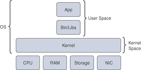
Figure 2-9 Operating System Kernel
There are two types of kernels: monolithic and microkernel. The difference between the two is that a monolithic kernel executes all its services and functions in the kernel space, which makes the kernel rigid and difficult to modify and enhance, whereas a microkernel only executes basic process communication and I/O control in the kernel space while the remaining system services such as the file system, device drivers, and so on, are executed in the user space. This makes microkernel OSs more flexible and allows for easy enhancements and modifications, which makes them ideal for cloud computing. Recent versions of Windows and macOS are examples of microkernel OSs.
Virtual Machines
As mentioned earlier in the “Cloud Fundamentals” section of this chapter, virtualization allows a physical server to run many independent operating systems and applications known as virtual machines (VMs). One of the main drivers behind virtualization was that server hardware resources were being underutilized, where servers were typically running a single application using only about 10 to 25% of the CPU utilization. VMs increase the overall efficiency and cost-effectiveness of a server by maximizing the use of the available resources.
Figure 2-10 illustrates a side-by-side comparison of a bare-metal server and a server running virtualization software. The virtualization software performing the hardware abstraction that allows multiple operating systems to run concurrently is known as a hypervisor. VMware vSphere, Microsoft Hyper-V, Citrix XenServer, and Red Hat KVM are the most popular hypervisors in the server virtualization market.

There are two types of hypervisors, as illustrated in Figure 2-11:
Type 1: This type of hypervisor runs directly on the system hardware. It is commonly referred to as “bare metal” or “native.”
Type 2: This type of hypervisor requires a host OS to run. This is the type of hypervisor that is typically used by client devices (for example, VMware Fusion).
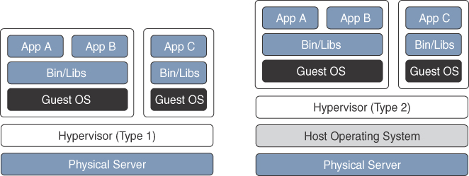
Figure 2-11 Type 1 vs. Type 2 Hypervisors
One key capability of VMs is that they can be migrated from one server to another while preserving transactional integrity during movement. This can enable many advantages; for example, if a physical server needs to be upgraded (for example, by adding more memory), the VMs can be migrated to other servers with no downtime. Another advantage is that it provides high availability; for example, if a server fails, the VMs can be spun up on other servers in the network, as illustrated in Figure 2-12.
Containers
A container, much like a VM, provides an isolated environment to run applications, and it can be moved between servers (they are portable). Even though they have these and many other similarities to VMs, containers are not the same as VMs and they should not be referred to as “lightweight VMs.”
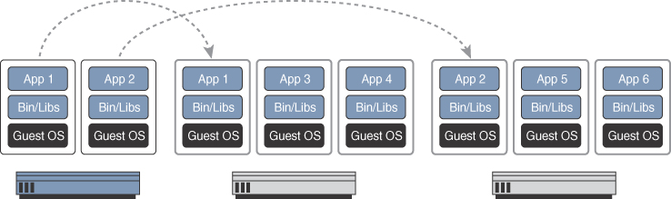
Figure 2-13 shows a side-by-side comparison of VMs and containers. Notice how each VM requires an OS and that containers all share the same OS while remaining isolated from each other.

A VM includes a guest OS, which typically comes with a large number of components (including libraries and dependencies) that are really not required for the application to run, and it’s up to the developer to strip any unwanted services or components from it to make it as lightweight as possible. Remember, a VM is just taking a physical server and virtualizing it, which means that it includes all of the components of a physical server, but in a virtual fashion.
Containers, on the other hand, share the underlying resources of the host operating system, and each application, along with the dependencies that it needs to run, is completely isolated, which makes the applications very lightweight (small size) and portable (easy to move/migrate). In other words, a container is typically just a tarball (that is, an archive file similar to a ZIP file) that packages the code, configuration, and dependencies of an application into a single file. This eliminates the typical problem of “It worked on my machine, why isn’t working on yours?” or the typical issue when trying to install an application and the needed libraries to run it are not part of the operating system and need to be downloaded (via apt-get, yum, and so on) to make it run.
A container does not try to virtualize a physical server like VMs do; instead, the abstraction is the application or the components that make up the application.
Here is one more example to help you understand the difference between VMs and containers: When a VM starts, the OS needs to load first, and once it’s operational, the application in the VM can then start and run, which usually takes minutes. When a container starts, it leverages the kernel of the host OS, which is already running, and it typically takes a few seconds to start.
To develop, deploy, and run applications with containers, a container runtime is required. Many container runtimes are available, with the most popular being Docker. Here’s a list of some of the other container runtime options available:
rkt (pronounced “rocket”)
Open Container Initiative
LXD (pronounced “lexdi”), from Canonical Ltd
Linux-VServer
Windows Containers
Cloud Native Applications and Services
As previously mentioned, one of the benefits of containers is that they make it easy for developers to know that their software will run, no matter where it is deployed, without having to worry about any dependencies their apps or components might have. Another benefit of containers is that they facilitate applications based on a microservices architecture. Instead of having one large, monolithic application, a microservices architecture breaks an application down into multiple, smaller components that can communicate with each other, and each of these components can be placed into a container. This facilitates a continuous integration/continuous delivery (CI/CD) approach, which increases feature velocity; in other words, different development teams can more easily work on different components of an application, and as long as they don’t make any major changes to how those application components interact, they can work independently of each other. This allows for delivering small batches of software into production continuously.
Cloud-native applications and services are specifically built for the cloud to leverage all the advantages of cloud computing (availability, elasticity, and so on), and they typically use containerized microservices. The reason for using containers and not VMs is that VMs are too heavy (since they emulate a full physical server with an OS) and are very slow to start, whereas containers are very lightweight and start fast.
Cloud-native applications or services are often developed using the 12 Factor App (https://12factor.net/) design methodology as a baseline. This methodology dictates that applications employ a number of best practices to ensure portability, flexibility, and resiliency. The 12 Factor App methodology was created by developers at Heroku and was presented for the first time by Adam Wiggins circa 2011.
Virtualization Functions
Network Functions Virtualization (NFV) is an architectural framework created by the European Telecommunications Standards Institute (ETSI) that defines standards to decouple network functions from proprietary hardware-based appliances and have them run in software on standard x86 servers. It also defines how to manage and orchestrate the network functions. A network function (NF) refers to the function performed by a physical appliance (for example, a firewall or a load balancer function).
Some of the benefits of NFV include benefits similar to server virtualization and cloud environments:
Reduced operator capital expenditure (CAPEX) and operational expenditure (OPEX) through reduced equipment costs and efficiencies in space, power, and cooling
Faster time to market (TTM) because VMs or containers are easier to deploy than hardware
Improved return on investment (ROI) from new services
Scale up/out and down/in capacity on demand (elasticity)
Openness to the virtual appliance market and pure software networking vendors
Opportunities to test and deploy new innovative services virtually and with lower risk
Figure 2-14 illustrates the ETSI NFV architectural framework.
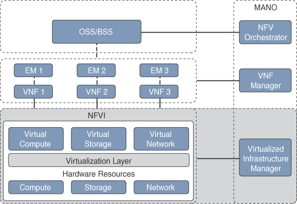
NFV infrastructure (NFVI) is all the hardware and software components that comprise the platform environment in which virtual network functions are deployed. It is the section highlighted in green in Figure 2-14.
A VNF, as its name implies, is the virtual or software version of an NF, and it typically runs on a hypervisor as a VM. VNFs are commonly used for L4–L7 functions such as those provided by load balancers (LBs) and application delivery controllers (APCs), firewalls, intrusion detection systems (IDSs), WAN optimization appliances, and so on. However, they are not limited to L4–L7 functions; they can also perform lower-level L2–L3 functions, such as those provided by routers and switches.
Some examples of Cisco VNFs include the following:
Cisco vEdge Cloud
Cisco Cloud Services Router 1000V (CSR 1000V)
Cisco Cloud Services Platform 2100 (CSP2100)
Cisco IOS XRv 9000 (XRv9000)
Cisco NextGen Firewall Virtual Appliance (NGFWv)
Cisco Adaptive Security Virtual Appliance (ASAv)
Cisco Web Security Virtual Appliance (WSAv)
Cisco Email Security Virtual Appliance (ESAv)
Cisco Advanced Malware Protection Private Cloud Virtual Appliance (AMPv)
The NFVI Virtualized Infrastructure Manager (VIM) is responsible for managing and controlling the NFVI hardware resources (compute, storage, and network) and the virtualized resources. It is also responsible for the collection of performance measurements and fault information. In addition, it performs lifecycle management (setup, maintenance, and teardown) of all NFVI resources as well as VNF service chaining.
Service chaining refers to chaining VNFs together to provide an NFV service or solution, as illustrated in Figure 2-15.

The element managers (EMs), also known as element management systems (EMSs), are responsible for the functional management of VNFs; in other words, they perform fault, configuration, accounting, performance, and security (FCAPS) functions for VNFs. A single EM can manage one or multiple VNFs, where an EM can also be a VNF.
The NFV Orchestrator is responsible for creating, maintaining, and tearing down VNF network services. If multiple VNFs are part of a network service, the NFV Orchestrator enables the creation of an end-to-end network service over multiple VNFs. The VNF Manager manages the lifecycle of one or multiple VNFs as well as FCAPS for the virtual components of a VNF. The NFV Orchestrator and VNF Manager together are known as NFV Management and Orchestration (MANO).
Operations support system (OSS) is a platform typically operated by service providers (SPs) to support all their network systems and services. The OSS can assist them in maintaining network inventory, provision new services, configure network devices, and resolve network issues. It commonly operates in tandem with the business support system (BSS) to improve the overall customer experience. BSS is a combination of product management, customer management, revenue management (billing), and order management systems that are used to run the SP’s business operations.
Cisco’s NFVI solution addresses the following key SP requirements:
Carrier-class performance: In the same way physical devices provide carrier-class performance, the NFVI platform should provide carrier-class performance.
Use-case-agnostic infrastructure: Capability to use NFVI as a platform on which to onboard multiple use cases.
Open standards based, modular, and elastic: Being open and interoperable allows for onboarding any VNF from any third-party vendor in a modular and elastic manner.
Easy to use with unified management: Single pane of glass to manage the lifecycle of the NFVI platform.
Integrated solution with single point of ownership: Satisfies the demand for an NFVI platform from a single vendor. Having a single point of ownership makes it easier for the operation and support on a day-to-day basis.
Multilevel security: Ensures all the components that comprise NFVI are secure and not easily susceptible to attacks (such as hacking, DDoS, and so on).
Figure 2-16 shows Cisco’s NFV solution architecture that was designed to meet the NFVI standards as well as the requirements just discussed. The NFVI components are shown in the green box, which should be looked at as a single integrated platform (composed of software and hardware) that can be used to deploy VNFs.

The solution has been tested to onboard simple and complex VNFs from multiple third-party vendors spanning different network services—for example, routing, firewalls, session border controllers, Virtualized Evolved Packet Core (vEPC), Virtualized Policy and Charging Rules Function (vPCRF), Virtualized IP Multimedia System (vIMS), and so on.
The components shown at the top of Figure 2-16 include Cisco’s and third-party VNFs as well as Cisco’s Network Services Orchestrator (NSO) as the NFV orchestration component and Cisco’s Elastic Services Controller (ESC) as the VNF Manager. These components, although part of Cisco’s NFV solution, are optional, and the customer may choose any third-party components that meet the NFV requirements.
There are currently three Cisco-integrated solutions available that rely on Cisco’s NFV solution offering:
Cisco Managed Services Accelerator (MSX): Delivers virtual customer premises equipment (vCPE), cloud VPN, SD-WAN, Mobile Enterprise, Managed Security, and Collaboration cloud-based services
Cisco Ultra Services Platform: With this solution, mobility services for machine-to-machine (M2M), IoT, machine-to-people (M2P), or people-to-people (P2P) applications can be turned up in days, for example, connected cars, homes and businesses. It lowers the total cost of ownership (TCO) by transitioning services from a centralized to a distributed Mobile Virtual Network Operator (MVNO), and it can also be used to provide cloud-based services such as Mobility as a Service, Mobile Enterprise and Voice-over-LTE (Volte).
Cisco Virtualized Video Processing: Orchestrates virtual video functions such as encoding, multiplexing, ad splicing, encrypting, transcoding, recording, packaging, playout, and delivery to provide the ability to operate a single production line for all video workflows.
Note
MSX was formerly Cisco Virtual Managed Services (VMS).
Cloud Connectivity
Typically, an organization that decides to adopt a public cloud starts by connecting its on-prem networks to the cloud providers via an Internet VPN connection, simply because it is a great, simple, and affordable option to connect to them. If the organization has certain applications that require high throughput and low latency/jitter, then relying entirely on Internet VPN connections might not be enough. Fortunately, there are alternatives to connect to the “big three” CSPs (AWS, Microsoft Azure, and GCP), which are discussed in this section.
AWS
This service establishes a dedicated network connection between a customer’s private network and the closest AWS geographic region with which the customer location is associated. A customer’s WAN router connects to one of many AWS’s DX locations, which are directly connected to AWS. This provides access to all of the services offered within that specific AWS geographic region. Using 802.1q virtual LANs (VLANs), the same dedicated connection can be used to access AWS’s VPCs as well as all public AWS services in all other public regions (for example, AWS S3).
The DX connectivity options available are as follows:
Co-location: The customer’s network is co-located with an existing AWS DX location.
Partner: The customer connects to an AWS DX partner who is a member of the AWS Partner Network (APN).
Independent Service Provider: The customer connects to an independent service provider to connect to AWS DX.
Speeds of 1Gbps to 10Gbps are available through the co-location option for a single link. Speeds of 50Mbps to 500Mbps can be ordered from any APN partner supporting AWS Direct Connect.
Microsoft Azure ExpressRoute (ER)
Microsoft’s direct network connectivity option ExpressRoute (ER) allows for the extension of a private network to any of Microsoft’s cloud services, including Microsoft Azure, Office 365, and Dynamics 365. A customer’s WAN router connects to one of many peering locations and gains access to all regions within the geopolitical region. A premium add-on is available to extend connectivity across geopolitical regions around the world.
The ExpressRoute connectivity options available are as follows:
Co-location: Co-location providers at a cloud exchange can offer either Layer 2 cross-connections or managed Layer 3 cross-connections between the customer’s network and the Microsoft cloud.
Point-to-point Ethernet connections: Point-to-point Ethernet providers can offer Layer 2 connections or managed Layer 3 connections between the customer’s site and the Microsoft cloud.
Any-to-any (IPVPN) networks: Customers can integrate their WAN with the Microsoft cloud via an MPLS L3VPN provider (IPVPN). The Microsoft cloud can be interconnected to the customer’s WAN to make it look just like any other branch office.
Speeds supported range from 50Mbps to 10Gbps.
Google Cloud Dedicated Interconnect
Cloud Interconnect provides two options for extending the customer’s private network into their GCP VPC networks.
The Google Cloud Dedicated Interconnect connectivity options available are as follows:
Dedicated Interconnect (co-location): Provides direct physical connections between the customer’s private network and Google’s network. The customer’s network must physically meet Google's network in a Google-supported co-location facility.
Partner Interconnect: Partner Interconnect provides Layer 2 or Layer 3 connectivity between the customer’s private network and the VPC network through a supported service provider partner. A Partner Interconnect connection is useful when the customer’s private network is in a physical location that can’t reach a Dedicated Interconnect co-location facility or if the customer data needs don’t warrant an entire 10Gbps connection.
The Dedicated Interconnect option supports speeds of 10Gbps per circuit with a maximum of eight circuits per Dedicated Interconnect connection. If less speed is desired, then the Partner Interconnect option offers speeds of 50Mbps and up to 10Gbps per VLAN attachment.
Region and Availability Zone Concepts
The “big three” CSPs (AWS, Microsoft Azure, and GCP) as well as other CSPs such as IBM have global infrastructures that are built around regions and zones. How each CSP defines regions and zones varies slightly, but in the end, they all serve the same purpose. In this section, AWS will be used as an example to define regions and zones.
AWS has multiple regions around the world. A region is an independent separate geographic area, and each region has multiple, isolated availability zones (AZs) that are connected to each other through low-latency links, as illustrated in Figure 2-17. Customers can deploy their applications and databases across multiple AZs within a region to make them highly available, fault tolerant, and scalable.
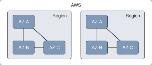
In addition, to increase redundancy and fault tolerance even further, AWS allows for replicating applications and data across multiple regions. Resources aren’t replicated across regions unless explicitly specified.
Multicloud Connectivity
Organizations all over the world are on a nonstop trend of using multiple CSPs, in part due to the different cloud services and functionalities each one of them offers. However, most organizations are not fully migrating their applications and data to the CSPs; instead, CSPs are becoming extensions to their on-prem or private-cloud environments where workloads and data are expected to move across their WAN to multiple CSPs, as well as between CSP VPCs/vNETs, while providing secure connectivity.
Using the basic networking services provided by CSPs such as DirectConnect, ExpressRoute, and so on, is not enough to provide the visibility and capabilities that are needed to achieve multicloud connectivity.
One of the ways to achieve multicloud connectivity is by using a virtual router such as the CSR 1000V router. The CSR 1000V ensures secure, scalable, and consistent connectivity for multicloud networking. It can run on VMware ESXi, Red Hat KVM, Citrix Xen, and Microsoft Hyper-V, as well as on Microsoft Azure and Amazon Web Services. Some of the security features it supports include IPSec VPNs and built-in zone-based firewalls. It also supports Cisco Digital Network Architecture (DNA) Encrypted Traffic Analytics (ETA), which has the ability to find threats in encrypted traffic.
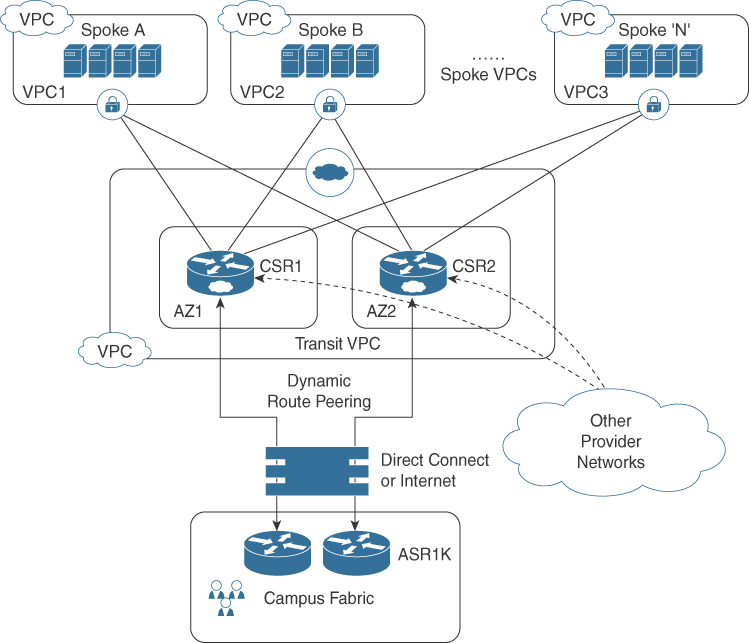
Cisco has co-developed solutions using the CSR 1000V with cloud providers such as Transit VPC/VNET. The Transit VPC solution, illustrated in Figure 2-18, is a hub-and-spoke design built on AWS by deploying two CSRs in the transit VPC (the hub) for redundancy and using AWS VGWs (virtual private gateways) on the spoke VPCs, which host customer applications. The spoke VPCs join the transit VPC via automation, and this allows for spoke VPCs to be able to communicate with each other. The on-prem network can also be extended into the cloud securely using IPSec encryption through the Transit VPC. This is useful for enterprise customers using multiple VPCs for different departments or projects, such as Development VPC, Production VPC, and Test VPC, and they need connectivity between VPCs as well as to on-prem resources.
Software-Defined Access (SD-Access) User-to-Cloud Access Control
SD-Access is the industry’s first intent-based networking solution for the enterprise built on the principles of Cisco’s Digital Network Architecture (DNA). It provides automated end-to-end segmentation to separate user, device, and application traffic without having to redesign the network. SD-Access is the combination of the following components:
DNA Center: An enterprise SDN controller that provides a graphical user interface (GUI) that is the single pane of glass for management and provides all of the base and fabric automation services. It also provides analytics and assurance services with the integrated Cisco Network Data Platform (NDP) software.
Identity Service Engine (ISE): Provides all of the identity and policy enforcement services.
Campus Fabric: An evolved campus network that allows for host mobility without stretching VLANs, network segmentation without Multiprotocol Label Switching (MPLS), and RBAC without end-to-end support for TrustSec.
SD-Access can be used to extend TrustSec into AWS Transit VPC to control access to spoke VPCs. This can be achieved based on Security Group Tags (SGTs) and ISE policy enforcement on the Transit VPC Hub CSR 1000Vs, as illustrated in Figure 2-19. The table in the lower left of the figure shows the VPCs the end users would have access to according to their role.
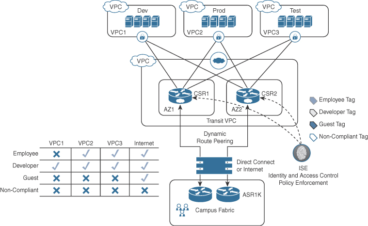
This is all deployed from the DNA Center GUI, which works along with ISE to push the SGT Tag and Policy Enforcement configuration to the CSR 1000Vs. Extending TrustSec to the Transit VPC Hub has the following benefits:
Control traffic between VPCs
Simplify security configurations
Scale security group control
Single control point
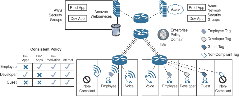
Figure 2-20 illustrates another way to enforce user-to-cloud access control by extending TrustSec to a virtual firewall or SGACL-capable virtual router in the cloud environments, such as Cisco Firewpower Threat Defense Virtual (FTDv), ASAv, CSR 1000V, or Integrated Services Virtual Router (ISRv), to provide policy enforcement at the application level within a VPC rather than at the VPC level, as in the previous transit VPC case. The SGT policy is pushed by ISE to the virtual router or firewall, and it can then be mapped to the cloud provider’s own Security Groups. The table in the lower left of the figure shows the apps the end users would have access to according to their role.
Software-Defined WAN (SD-WAN)
Managing enterprise networks is becoming more complex, with customers embracing a multicloud approach, applications moving to the cloud, mobile and IoT devices growing exponentially in the network, and Internet edge moving to the branch. This digital transformation is powering the adoption of SD-WAN by customers looking to do the following:
Lower costs and risks with simple WAN automation and orchestration.
Extend their enterprise networks (such as branch or on-prem) seamlessly into the public cloud.
Provide optimal user experience for SaaS applications.
Be able to leverage a transport-independent WAN for lower cost and higher diversity.
Enhance application visibility and use that visibility to improve performance with intelligent path control to meet SLAs for business-critical and real-time applications.
Provide end-to-end WAN traffic segmentation and encryption for protecting critical enterprise compute resources.
Cisco currently offers three SD-WAN solutions:
Cisco SD-WAN (Cisco + Viptela)
Meraki SD-WAN
Cisco Intelligent WAN (IWAN)
The following guidelines should be considered when deciding which SD-WAN solution is the right choice for the business:
Cisco SD-WAN (based on Viptela): This is the preferred solution for organizations that require an SD-WAN solution with cloud-based initiatives that provides granular segmentation, advanced routing, and complex topologies while connecting to cloud instances. This solution is based on Viptela’s vEdge platform.
Meraki SD-WAN: This is the recommended solution for organizations that require unified threat management (UTM) solutions with SD-WAN functionality or are existing Cisco Meraki customers looking to expand to SD-WAN. UTM is an all-in-one security solution delivered in a single appliance and typically includes the following security features: firewall, VPN, intrusion prevention, antivirus, antispam, and web content filtering.
Cisco IWAN: Cisco’s first SD-WAN solution on the ISR platform that provides advanced services such as voice, compute, WAN optimization, integrated threat control capabilities, switching, and so on.
Note
At the time of writing, Viptela functionality was actively being integrated into all IOS XE enterprise routing platforms, such as Integrated Services Router (ISR), CSR, ASR 1000 Series Router (ASR1K), CSR 1000V, and Enterprise Network Compute System 5K (ENCS 5K) platforms, along with the advanced services mentioned previously (voice, compute, and so on). This will bring Viptela/Cisco SD-WAN the advance service capabilities of IWAN through a simple software upgrade.
All three SD-WAN solutions work in a similar fashion, but in this chapter only Cisco SD-WAN based on Viptela will be covered.
Cisco SD-WAN
Cisco SD-WAN is a cloud-delivered overlay WAN architecture that facilitates digital and cloud transformation for enterprises, and it addresses all of the customer requirements mentioned earlier. Figure 2-21 illustrates Cisco’s SD-WAN solution architecture.
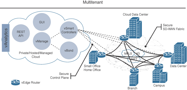
The Cisco SD-WAN solution is composed of four main components and an optional analytics service:
vManage: This is a single pane of glass network management system (NMS) GUI used to configure and manage the full SD-WAN solution. It enables centralized provisioning and simplifies changes.
vSmart: This is the brains of the solution. It establishes a secure Datagram Transport Layer Security (DTLS) connection to all vEdge routers in the SD-WAN fabric and runs a proprietary Overlay Management Protocol (OMP) to share routes, security, and policy information. It implements all of the control plane policies created on vManage, such as service chaining, traffic engineering, and segmentation per VPN topology.
For example, when a policy is created on vManage for an application (such as YouTube) that requires no more than 1% of loss and 150ms of latency, that policy is downloaded to the vSmart controller. vSmart will take the policy and convert it into a format that all the vEdge routers in the fabric can understand, and it automatically implements the policy on all vEdge routers without the need to rely on a command-line interface (CLI). The vSmart controller also works in conjunction with the vBond orchestrator to authenticate the devices as they join the network and to orchestrate connectivity between the vEdge routers
vEdge routers: These are routers that support standard router features, such as OSPF, BGP, ACLs, QoS, and routing policies, in addition to the SD-WAN overlay control and data plane functions. Each vEdge router automatically establishes a secure DTLS connection with the vSmart controller and standard IPSec sessions with other vEdge routers in the fabric.
vBond orchestrator: The vBond orchestrator authenticates the vSmart controllers and the vEdge routers orchestrate connectivity between them. It is the only device that must have a public IP address so that all Viptela devices in the network can connect to it.
vAnalytics: This is an optional analytics and assurance service that has many advanced capabilities, including the following:
Visibility of applications and infrastructure across the WAN
Forecasting and “what if” analysis
Intelligent recommendations
These capabilities can bring many benefits that are not possible without vAnalytics; for example, if a branch office is experiencing latency or loss on its MPLS link, vAnalytics will detect this, and it will then compare that loss or latency with other organizations in the area that it is also monitoring to see if they are also having that same loss and latency in their circuits. If they are, they can then report this issue with confidence to their SPs. It can also help predict how much bandwidth is truly required for any location, and this is useful to decide if a circuit can be downgraded to a lower bandwidth, resulting in reduced costs.
Out of these components, the vEdge routers and the vBond orchestrator are available as physical appliances and VMs, whereas vManage and vSmart are only available as VMs.
All of the VMs, including the vEdge router, can be hosted on-prem using ESXi or KVM, or they can be hosted in AWS and Microsoft Azure.
Note
At the time of writing, vManage capabilities were being integrated into DNA Center to bring full DNA Center capabilities to Cisco SD-WAN, such as assurance, analytics, and integrated workflows.
Cisco SD-WAN Cloud OnRamp
Traditional enterprise WAN architectures are not designed for the cloud. As organizations adopt more SaaS applications like Office 365 and public cloud infrastructures like AWS and Microsoft Azure, the current network infrastructure poses major problems related to the level of complexity and end-user experience.
Cisco’s SD-WAN solution includes a set of functionalities addressing optimal cloud SaaS applications access and IaaS connectivity called Cloud OnRamp. Cloud OnRamp delivers the best application experience for SaaS applications by continuously monitoring SaaS performance across diverse paths and selecting the best-performing path based on performance metrics (jitter, loss, and delay), and it simplifies hybrid cloud and multicloud IaaS connectivity by extending the SD-WAN fabric to the public cloud while at the same time increasing high availability and scale.
Cloud OnRamp for SaaS
SaaS applications reside mainly on the Internet, and to be able to achieve optimal SaaS application performance, the best-performing Internet exit point needs to be selected.
Figure 2-22 illustrates a remote site with dual direct Internet access (DIA) circuits from two different Internet service providers (ISP1 and ISP2). When Cloud OnRamp for SaaS is configured for a SaaS application on vManage, the vEdge router at the remote site will start sending small HTTP probes to the SaaS application through both DIA circuits to measure latency and loss. Based on the results, the vEdge router will know which circuit is performing better and will send the SaaS application traffic out of that circuit (ISP2). The process of probing continues, and if a change in performance characteristics of the ISP2’s DIA circuit occurs (for example, due to loss or latency), the remote site vEdge router will make an appropriate forwarding decision.

Figure 2-23 illustrates another example of Cloud OnRamp for SaaS. The remote site has a single DIA circuit to ISP1 and an SD-WAN fabric DTLS session to the regional hub.

Similar to the previous case, Cloud OnRamp for SaaS can be configured on the vManage and become active on the remote site vEdge router. However, in this case, Cloud OnRamp for SaaS also gets enabled on the regional hub vEdge router and is designated as the gateway node. Quality probing service via HTTP toward the cloud SaaS application of interest starts on both the remote site vEdge and the regional hub vEdge.
Unlike the HTTP probe sent towards the SaaS application via the DIA link, Bidirectional Forwarding Detection (BFD) runs through the DTLS session between the remote site and the regional hub. BFD is a detection protocol originally designed to provide fast forwarding path failure detection times between two adjacent routers. For SD-WAN, it is leveraged to detect path liveliness (up/down) and measure quality (loss/latency/jitter and IPSec tunnel MTU).
For SaaS over DIA, BFD is not used because there is no vEdge router on the SaaS side to form a BFD session with. The Regional hub vEdge router reports its HTTP connection loss and latency characteristics to the remote site vEdge router via an Overlay Management Protocol (OMP) message exchange through the vSmart controllers. At this time, the remote site vEdge router can evaluate the performance characteristics of its local DIA circuit versus the performance characteristics as reported by the regional hub vEdge. It also takes into consideration the loss and latency incurred by traversing the SD-WAN fabric between the remote site and the hub site (calculated via BFD) and then makes an appropriate forwarding decision sending application traffic down the best performing path toward the cloud SaaS application of choice.
The quality of cloud SaaS application connection is quantified as a Viptela Quality of Experience (vQoE) score on a scale of 0 to 10, with 0 being the worst quality and 10 being the best. vQoE can be observed in the vManage GUI.
Cloud OnRamp for IaaS
Multicloud is now the new norm for enterprises. With multicloud, certain enterprise workloads remain within the boundaries of the private data centers, while others are hosted in the public cloud environments, such as Amazon Web Services (AWS) and Microsoft Azure. This approach provides enterprises the greatest flexibility in consuming compute infrastructure, as required.
With the Cisco Software-Defined WAN (SD-WAN) solution, you can extend ubiquitous connectivity, zero-trust security, end-to-end segmentation, and application-aware Quality of Service (QoS) policies of the organizational WAN into the IaaS environments, as illustrated in Figure 2-24. The transport-agnostic capability of the Cisco SD-WAN solution allows the use of a variety of connectivity methods by securely extending the SD-WAN fabric into the public cloud environment across all underlying transport networks. These include the Internet, MPLS, 3G/4G LTE, satellite, and dedicated circuits such as AWS’s DX and Microsoft Azure’s ER.
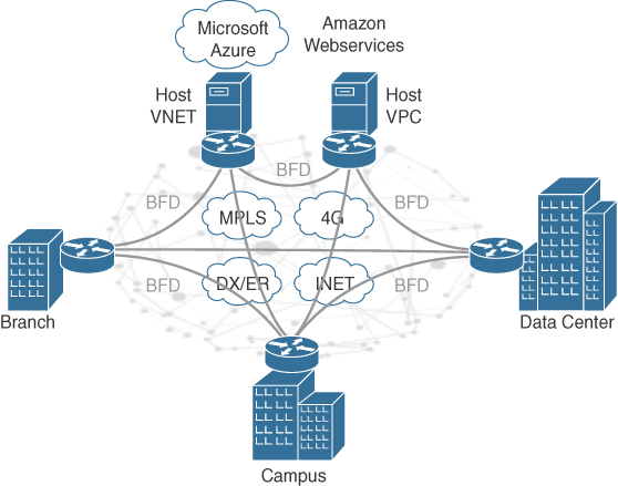
Virtual Switching
A virtual switch (vSwitch) operates like a physical Layer 2 Ethernet switch, and it enables VMs to communicate with each other within a virtualized server and with external physical networks via the physical network interface cards (pNICs). Multiple vSwitches can be created under a virtualized server, but network traffic cannot flow directly from one vSwitch to another vSwitch within the same host, and they cannot share the same pNIC.
Figure 2-25 illustrates a virtualized server with three vSwitches connected to the virtual network interface cards (vNICs) of the VMs as well as the pNICs. vSwitch1 and vSwitch3 are uplinked to pNIC 1 and pNIC 3, respectively, to access the physical network, whereas vSwitch2 is not uplinked to any pNICs. Since network traffic cannot flow from one vSwitch to another, network traffic from VM1 destined to the external network, or VM0, will need to flow through the firewall (NGFWv).

The downside to using standard vSwitches is that every vSwitch that is part of a cluster of virtualized servers needs to be configured individually in every virtual host, which is where distributed switching comes into the picture. Distributed virtual switching is a feature that aggregates vSwitches together from a cluster of virtualized servers and treats them as a single distributed virtual switch. These are some of the benefits of distributed switching:
Centralized management of vSwitch configuration for multiple hosts in a cluster, which simplifies administration
Allows for networking statistics and policies to migrate with virtual machines during a live VM migration
Configuration consistency across all the hosts that are part of the distributed switch
Examples of virtual distributed switches include Cisco Nexus 1000V, Cisco VM-FEX, Cisco AVS, HPE 5900v, Open vSwitch (OVS), IBM DVS 5000v, and vSphere Distributed Switch.
Table 2-3 provides a quick glance at the vSwitch options available from multiple vendors.
Table 2-3 The Most Popular vSwitch Options
Hypervisor |
Native vSwitch |
Third Party |
vSphere |
Standard vSwitch Distributed Virtual Switch |
Cisco Nexus 1000V* Cisco VM-FEX* IBM DVS 5000V* HPE 5900v* |
Hyper-V |
Native Hyper-V Virtual Switch |
Cisco Nexus 1000V Cisco VM-FEX NEC Broadcom |
KVM |
Linux Bridge (some distributions include OVS natively) |
Cisco Nexus 1000V OVS |
XEN |
OVS |
OVS |
* VMware ceased support for the third-party virtual switches starting with vSphere 6.5U2 and beyond.
Containers, just like VMs, also rely on vSwitches (aka virtual bridges) for communication within a node (server). Docker, for example, by default creates a virtual bridge called Docker0, and it is assigned the default subnet block 172.17.0.1/16. This default subnet can be customized, and user-defined custom bridges can also be used.
Figure 2-26 illustrates how every container created by Docker is assigned a virtual Ethernet interface (veth) on Docker0. The veth interface appears to the container as eth0. The eth0 interface is then assigned an IP address from the bridge’s subnet block. As more containers are created by Docker within the node, they are each assigned an eth0 interface and an IP address from the same private address space. This results in all containers being able to communicate with each other only if they are within the same node. Containers in other nodes are not reachable by default, which is something that needs to be managed via routing at the OS level, or by using an overlay network.
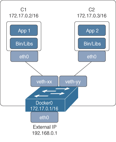
If Docker is installed on another node using the default configs, then it will end up with the same IP addressing as the first node, and this needs to be resolved on a node-by-node basis.
A better way to manage and scale containers and the networking connectivity between them within and across nodes is to use a container orchestrator such as Kubernetes, which is described in the next section, “Automation and Orchestration Tools.”
Automation and Orchestration Tools
To be able to achieve scalable multicloud environments, it is necessary to use automation and orchestration tools. Trying to manually create VMs, containers, applications, application migrations, and provision networks is not the way to go. With orchestrators and automation, all of these actions are abstracted and can be executed from a GUI.
Kubernetes
Google has been using containers for over a decade. Every application that runs at Google—for example, Gmail, Google apps, YouTube, or GCP—is a distributed application that run on containers, so needless to say, Google is an expert in managing distributed containerized applications at scale. In June 2015, Google published a research paper at Eurosys with details about Borg, Google’s internal container-oriented large cluster-management system.
Kubernetes is a container orchestrator that supports cloud and bare-metal environments, and it is the open-source version of Google’s Borg. Kubernetes is an entirely new codebase (meaning the code was entirely rewritten) that incorporates the best ideas from Borg into Kubernetes, and it addresses lessons learned and pain points that users identified with Borg over the years. Additionally, many of the developers at Google working on Kubernetes were formerly developers on the Borg project.
Other container orchestrations engines such as Docker Swarm exist, but Kubernetes is the most popular go-to container orchestration system in the industry.
Clusters, Nodes, and Pods
In Kubernetes, a cluster, as illustrated in Figure 2-27, is a collection of nodes. A node is a physical server or a virtual machine, and a pod is a collection of one or more containers that are all serving a specific purpose (usually they are all microservices that make up an application). A pod is the smallest entity that can be scheduled by Kubernetes; individual containers are not scheduled. Each pod gets assigned only one IP, and containers within the pod share the localhost address (that is, 127.0.0.1). A pod can be started, stopped, and replicated as a single unit, almost as if it was a VM.

Volumes
A pod volume (persistent storage) is required for containers that need to maintain the state of an application after reboots, relocations, and crashes. The reason for this is because a container file system only lives as long as the container does; if it restarts, any data and state will be lost.
Labels
In a Kubernetes environment many pods can be created, and to keep them organized, labels are necessary. Labels are nothing but a key-value pair, as shown in Figure 2-28. Label selectors can be used to request the apiserver (explained later) to retrieve a list of objects that match that label selector.

Kubernetes Cluster
Figure 2-29 illustrates a Kubernetes cluster that will be used as a reference to explain all of the basic components.
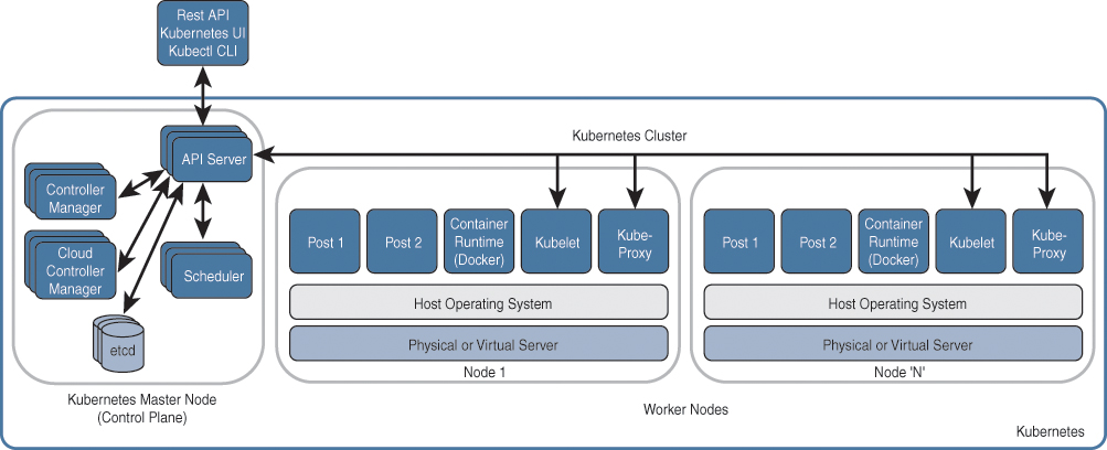
The Kubernetes master node can be thought of as the control plane of Kubernetes, and it is recommended to have at least three for redundancy. The master node is composed of five main components:
Note
In some special cases, the master node can also act as a worker node, which means it would also include a container runtime, a kubelet, and a kube-proxy.
API server: It services Representational State Transfer (REST) operations and provides the front end to the cluster’s shared state through which all other components interact. Every operation that involves changing the state of an object, such as a pod, needs to go through the API server.
etcd: It’s a distributed key-value store. Examples of data stored are jobs being scheduled, created, and deployed, labels, pod or service details and state, and replication information.
scheduler: It checks the environment to see where the workloads can run and create pods for them. Workloads come in all different shapes and sizes, and as they come in, the scheduler needs to figure out where to put them in a very similar way to a Tetris game.
controller-manager: The controller manager is a daemon that runs all the controllers included with Kubernetes. A control loop is a nonterminating loop that regulates the state of a system. A controller is a control loop that watches the shared state of the cluster through the apiserver and makes changes, attempting to move the current state toward the desired state.
Logically, each controller is a separate process, but to abstract complexity, they all run as a single process.
The worker nodes are where the pods are run, and they include the following components:
Container runtime: This is the software responsible for creating and managing the containers, where Docker is the default and most popular one. Other options include rkt, runc and any OCI runtime-spec implementation.
kubelet: A kubelet is an agent that runs on each node that receives the configuration for a pod from the apiserver and ensures that the defined containers are up and running and in a healthy state. The kubelet doesn’t manage containers that were not created by Kubernetes.
kube-proxy: kube-proxy acts as a network proxy for pods within a single worker node and for connections that originate from one pod to another pod and not connections coming from outside the cluster.
Note
In Kubernetes, the functionality of providing network proxy and load balancer capabilities is known as a service.
Kubernetes Networking
With default Kubernetes networking, as mentioned previously, each pod is assigned a single interface eth0 and a single IP address. All containers within a pod share a common networking space; in other words, if one container in the pod is running a web server listening on port 8080, another container within the same pod can connect to it using http://localhost:8080 or http://127.0.0.1:8080.
The default switch for a node is called cbr0 (instead of Docker0). This bridge is connected to the pods as well as to the external network. How it connects to the external network depends on the networking plug-in used.
Kubernetes allocates a user-configurable internal subnet range to each node, and from this range, it assigns an IP address to the bridge and to each pod within the node, as illustrated in Figure 2-30.

While there are many options on how to deploy an external network for inter-pod communication in Kubernetes, the Cisco recommended option is to use Cisco Application Centric Infrastructure (Cisco ACI), which is designed to offer policy-based automation, security, mobility, and visibility for application workloads, regardless of whether they run on bare-metal servers, hypervisors, or Linux containers. The Cisco ACI system-level approach extends the support for Linux containers by providing tight integration of Kubernetes.
Creating a Pod
A simple way to deploy a pod (or pods) is by creating a declarative YAML or JSON deployment configuration file. Declarative means the configuration file has instructions on what is desired (the intent), but it does not include details on how to do it; that is for Kubernetes to figure out.
The high-level steps that take place when a pod is created, as shown in Figure 2-31, are as follows:
The file is posted to the API server via a REST API post through the Kubernetes GUI, the kubectl CLI, or from an application such as CloudCenter.
The information in the file is then sent to the scheduler, and it is also stored in etcd.
The scheduler then needs to figure out what the intent is of the configuration file; understand the constraints, policies, requirements, and how many CPU cores the pod needs; see what the required memory is, as well as any affinity to a specific node, replica sets (how many pods should be created), a specific persistence requirement (volume), and so on. The scheduler then selects a node that meets the intent of the configuration file.
The scheduler sends a message to the kubelet running on the selected node concerning what the requirements are for the pod.
The kubelet then contacts Docker and instructs it on what it needs to do (for example, number of pods, number of containers within the pod, IP address assignment for the pod, image download, and so on). At this point, the pod is created and ready for use.
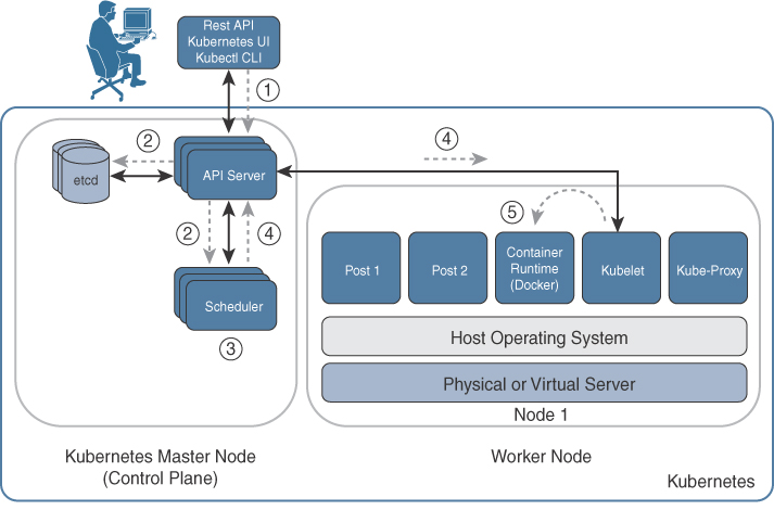
Figure 2-31 Creating a Pod Walkthrough
OpenStack
OpenStack is a cloud operating system that can be used to build private and public clouds; however, it is more prevalently used to build private clouds. It has a modular architecture, where each of its components (aka services or projects) is developed in individual development projects. Table 2-4 includes the OpenStack projects available in the Queens release. The services highlighted in bold are part of the core functionality of OpenStack.
Table 2-4 OpenStack Projects (Queens Version)
Project |
Service |
Description |
Horizon |
Web front end |
Provides a web-based dashboard to manage OpenStack |
Sahara |
Workload provisioning |
Provides simple means to provision a Hadoop cluster |
Magnum |
Workload provisioning |
Provisions container orchestration engines such as Kubernetes, Docker Swarm, and Mesos |
Trove |
Workload provisioning |
OpenStack Database as a Service (DBaaS) |
Murano |
Application lifecycle |
Presents cloud-ready applications in a browsable categorized catalog |
Freezer |
Application lifecycle |
Provides tools for backup, restore, and disaster recovery services |
Solum |
Application lifecycle |
Provides automation to make cloud services easier to consume and integrate into an application development process |
Aodh |
Orchestration |
OpenStack telemetry (ceilometer) alarming |
Senlin |
Orchestration |
Clustering service for OpenStack clouds |
Zaqar |
Orchestration |
Multitenant cloud messaging and notification service for web and mobile developers |
Heat |
Orchestration |
Manages OpenStack’s entire orchestration of infrastructure and applications |
Mistral |
Orchestration |
Workflow service for OpenStack cloud |
Blazar |
Orchestration |
A resource reservation service for virtual and physical resources |
Ironic |
Compute |
Provisions bare-metal servers |
Nova |
Compute |
Provisions virtual compute such as VMware, Xen, Hyper-V, KVM, and so on |
Zun |
Compute |
OpenStack containers service |
Designate |
Networking |
Provides DNS services to OpenStack tenants |
Octavia |
Networking |
Load Balancing as a Service (LBaaS) for OpenStack |
Neutron |
Networking |
Software-defined networking project that delivers Networking as a Service (NaaS) for OpenStack |
Cinder |
Storage |
Provides access and manages block-based storage (Ceph, CloudByte, and so on) for compute instances |
Swift |
Storage |
Distributed object storage system designed to scale |
Manila |
Storage |
Manages a shared file systems in a multitenant cloud environment |
Karbor |
Shared services |
Application Data Protection as a Service in OpenStack |
Keystone |
Shared services |
Provides identity services for OpenStack |
Glance |
Shared services |
Provides image management services for OpenStack and supports Raw, VirtualBox (VDI), VMware (VMDK, OVF), Hyper-V (VHD), and Qemu/KVM (qcow2) virtual machine images |
Searchlight |
Shared services |
Provides indexing and search capabilities across OpenStack resources |
Barbican |
Shared services |
REST API designed for key management |
Panko |
Monitoring tools |
Event storage and REST API for ceilometer |
Ceilometer |
Monitoring tools |
Provides telemetry services |
Monasca |
Monitoring tools |
Provides monitoring services |
Rally |
Optimization/policy tools |
Provides a framework for performance analysis and benchmarking for OpenStack components and full cloud deployments |
Congress |
Optimization/policy tools |
Provides governance and compliance services |
Watcher |
Optimization/policy tools |
Provides resource optimization services for OpenStack |
Vitrage |
Optimization/policy tools |
OpenStack Root Cause Analysis (RCA) Engine |
Cloudkitty |
Billing/business logic |
OpenStack Rating as a Service (RaaS) |
Tricircle |
Multi-region tools |
Provides networking automation across Neutron in multiregion OpenStack clouds deployment |
OpenStack-Ansible |
Deployment/lifecycle tools |
Ansible playbooks for deploying OpenStack |
Kolla |
Deployment/lifecycle tools |
Deploys OpenStack services as Docker containers |
Tripleo |
Deployment/lifecycle tools |
Heat templates for deploying OpenStack |
Kuryr |
Container infrastructure |
Docker network plug-in that uses Neutron to provide networking services to Docker containers |
Tacker |
NFV |
ETSI MANO NFV Orchestrator / VNF Manager |
Blazar |
Reservation |
A resource reservation service for virtual and physical resources |
Note
The codenames are usually related to the service function; for example, cinder provides block storage (to remember this, think of a cinderblock). As another example, ironic provisions bare-metal servers (think of iron as bare metal).
New versions of OpenStack are released every six months, which usually include new feature improvements and sometimes new projects. The OpenStack version-naming convention follows an alphabetical order—for example, Austin, Bexar, Cactus, Diablo, Essex, Folsom, Grizzly, Havana, Icehouse, Juno, Kilo, Liberty, Mitaka, Newton, Ocata, Pike, and Queens, with Queens being the latest release available at the time of writing.
Cisco CloudCenter (CCC)
CCC (formerly CliQr) is a multicloud platform for modeling, deploying, and managing applications with a simple architecture that includes two software components:
Cisco CloudCenter Manager (CCM): Single pane of glass for CCC
Cisco CloudCenter Orchestrator (CCO): Deployed locally on every cloud and on-prem environment.
CCM is the primary interface for users and administrators, and it can be accessed through a web browser user interface, CLI, or REST API. It includes all the management tools required for modeling, securely deploying, and managing applications in multiple on-prem, private cloud and public cloud environments. It also includes functions that can be used by administrators to have full visibility and control across all applications, users, governance rules, and clouds. For a traditional on-prem CCM deployment, the manager is delivered as a preinstalled virtual appliance, and only one CCM is required for each deployment, but additional managers can be added to meet disaster-recovery or high-availability requirements. CCM supports multitenancy, which means it can be used with multiple fully or partially isolated tenants, as needed.
A manager is linked to one or many orchestrators, and it can scale to simultaneously support thousands of applications.
Figure 2-32 illustrates the CloudCenter Multicloud Management Platform.
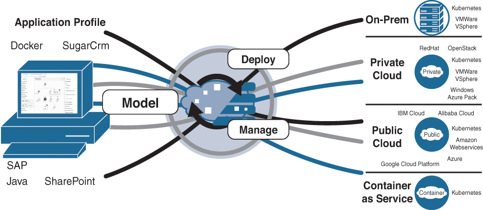
In Figure 2-32, Model refers to a CCC user-created application profile that describes how applications should be deployed, configured, and managed. The application profile model enables quickly and easily onboarding new or existing applications in any supported on-prem or cloud environment.
Figure 2-33 shows CCM’s simple, visual topology modeler. Creating an application profile is as easy as dragging and dropping from the library of ready-to-use or customized services, images, and containers on the left pane onto the topology modeler and then just adding the connections between them. The application can be modeled with a mixture of containers, VMs, and services.

An application profile does not require any cloud-specific information to be provided or to hardwire the profile to any cloud infrastructure; it is completely cloud agnostic. For example, Figure 2-34 illustrates the traditional approach to deploy an application into different cloud environments via automation by using workflows and scripts that are uniquely developed for each environment the application needs to be deployed on.

Figure 2-35 illustrates how CloudCenter takes an application-centric approach, where the application profile is modeled once, and it can then be deployed and managed on any supported environment. This eliminates environment-specific automation that locks applications and workloads into a single cloud environment. CloudCenter abstracts the cloud and does the heavy lifting of understanding translating the application profile into the target cloud’s native APIs.

Deploy simply refers to clicking on the deploy button to deploy a new application profile as well as related components and data to any on-prem or cloud environment.
Manage refers to applying a wide range of application lifecycle actions to set policies to enable in-place scaling, support cross-environment bursting or high availability and disaster recovery, and start and stop the deployment
Cisco CloudCenter Orchestrator is a technology that decouples applications from the underlying infrastructure by abstracting the resources of the environment it is running on. One Orchestrator is deployed locally in each private cloud, public cloud, or on-prem environment and orchestrates the initial deployment of the application profile and all ongoing management requests that come from CCM. The CCM does not communicate directly with the cloud infrastructure; instead, it connects to the CCO via a REST API and sends it information and instructions, including application profiles, runtime policies, and application lifecycle management commands such as deploy, start, stop, and remove. The Orchestrator runs those commands and sends a status update back to the CCM.
The Orchestrator abstracts the unique API and services offered by each cloud, and it uses the same communication mechanism back to the Manager regardless of the cloud on which the Orchestrator is installed.
Artifact Repositories
Organizations typically maintain application packages, data, and scripts in multiple repositories of their choice. Artifact repositories can be used to link to an existing repository to store and access files and to point to application binaries, scripts, and shared files. The preconfigured Cisco CloudCenter Network File System (NFS) options can be used to mount storage with multiple disks and encryption.
When an application or application profile is being modeled, the relevant repository can be selected to provide the relative path to the application packages, scripts, or files. The list of available repositories is displayed for user selection.
Multitenant
Cisco CloudCenter offers various multitenant models to support typical enterprise IT multicloud use cases, as shown in Figure 2-36.
Full isolation: With Cisco CloudCenter, each tenant can be fully isolated from other peer tenants. In this way, two completely independent business units can use a single Cisco CloudCenter instance while strictly separating tenants.
Partial isolation: Cisco CloudCenter offers an option for partial isolation between parent and child tenants. In some cases, a central IT organization may offer shared services, delivered either on-prem or through the CSP, that are consumed by various business units that are independent. For independent IT departments, the central IT organization may want to enforce OS image standards, require use of specific artifact repositories, or require a common rules-based governance framework.
Flexible sharing: Cisco CloudCenter facilitates sharing within each tenant. Powerful features for sharing application profiles, application services, deployment environments, and more multiply the speed and agility benefits of an application-defined management solution.

Figure 2-36 CCC Multitenant Models
Application Migration
As seen earlier in “Workload Migration” section of this chapter, migrating applications to the cloud can be overwhelming and time consuming, and organizations want to move to the cloud as fast as possible and with the least amount of downtime. In a typical on-prem-to-cloud migration, VMs are migrated one at a time. However, the problem is that applications are sometimes spread out across a group of virtual machines, and moving one of them into the cloud can create an orphaned state for an application. Therefore, it is necessary for all the VMs that make up the application to be migrated as a group.
It’s a challenge to find all the application components for existing applications not created via CloudCenter (also known as brownfield applications), but with the help of application discovery tools, the application dependencies can be derived and the grouping of virtual machines that make up the application can be discovered. Once the application discovery is done, the migration of the application can be planned.
Planning for a multiphase approach for migration, as illustrated in Figure 2-37, is essential. This approach helps in the effective migration of applications by segregating the tasks according to their functional aspects. The Cisco CloudCenter solution simplifies the application migration process.
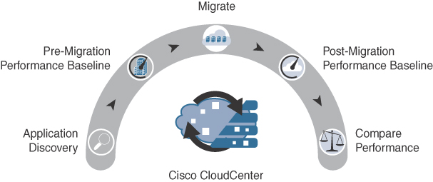
Application Discovery
Collecting information about the brownfield (legacy) applications in the existing environment is critical to understanding its interdependencies and planning how the application should be migrated. When migrating applications, the goal is to migrate the full application and avoid anything that would lead to an orphaned state for the application during or after the migration. To aid with the application discovery, iQuate iQcloud is recommended since it is the most advanced application discovery solution available.
iQuate provides an agentless SaaS service, which means there is no need to install agents on the VMs to monitor them; all that is required is to install an iQuate virtual appliance in the environment where the applications reside and to provide the login credentials for the VMs that need to be monitored. That is all it needs to generate a report with application discovery data.
Pre-migration Performance Baseline
To make sure that the application performance is the same or better in the public cloud, a pre-migration performance baseline needs to be performed. The application discovery data report generated by iQuate can be used to identify the VMs that make up the full application. The VMs are imported into CCC to enable AppD agents on them to capture the performance baseline of the application before migration based on technical and business metrics. Using technical and business metrics for the performance baseline allows measuring the performance not only at the technical level but also at the business level (for example, the end-user experience with the application, understanding business key performance indicators, and so on).
Migrate
After application discovery and initial performance baselining, the application can now be migrated. Two types of migrations can be performed:
Lightweight: This type of migration is for applications that were created using a CCC application model. To migrate the application, CCC makes a backup of the application, its metadata, and its database in the current environment and redeploys the application in the target environment by restoring its metadata and database. This type of migration is lightweight since only the application is redeployed and not the full VM.
Heavyweight: This type of migration is for brownfield applications. These applications need to be migrated using lift-and-shift-type migration tools. The lift-and-shift migration, as explained earlier in this chapter in the “Workload Migration” section, allows the application to be migrated without re-architecting or redesigning it, making it a less disruptive and quicker application migration.
Cisco CloudCenter uses CloudEndure Live Migration for heavyweight migrations, which is another SaaS service to migrate the application VMs to different clouds such as Amazon Web Services (AWS), Microsoft Azure, and Google.
Post-migration Performance Baseline
Once the application migration is complete, performance baselining is done again with AppD using the same technical and business metrics as the on-premises performance baselining.
Compare Performance
Using the pre-migration and post-migration performance baselines, you can compare the application’s technical and business metrics. Technical metrics can be used by DevOps and application owners to gain confidence in the migration methodology, and the business metrics help in understanding end-user behavior and application interaction.
Summary
In this chapter, a basic definition of cloud was provided using NIST’s definition, which includes the following characteristics and models:
Essential Characteristics
On-demand self-service: Portal
Measured service: Billing
Rapid elasticity: Scale out and scale in automatically
Resource pooling: Massive shared resources
Broad network access: Ubiquitous access for any device
Service Models
Infrastructure as a Service (IaaS)
Platform as a Service (PaaS)
Software as a Service (SaaS)
Everything as a Service (XaaS)
Cloud Deployment Models
Public cloud
Private cloud
Community cloud
Hybrid cloud
Multicloud (not defined by NIST)
Performance, scalability, and high availability for cloud were described with more focus on how to apply features and technologies (WAAS, PfR, and so on) to enhance application performance, which is directly correlated to what matters the most—the end-user experience.
How organizations share security risks and responsibilities with the CSPs was explained, as was security compliance guidelines, cloud threats, and recommendations on how to secure the cloud with Cisco solutions.
A workload migration strategy was also discussed, giving you a high-level methodology on the steps that need to be taken for successful workload migration into a cloud environment.
Virtual machines and containers were described and compared. Also, a brief introduction was given showing how containers enable cloud native applications using microservices architectures.
The NFV architectural framework section introduced the concept of appliance virtualization, where networking elements can also be virtualized (called VNFs) and decoupled from their proprietary hardware. Cisco’s NFVI platform was explained, which stems from the NFV framework and can be used to load VNFs of any kind, including third-party VNFs.
The various cloud connectivity options offered by the three leading CSPs—Microsoft Azure, GCP, and AWS—were discussed. These include direct connect, co-location, and IPSec VPN (the most popular). User-to-cloud access control using TrustSec SGTs and the CSR 1000V as well as other Cisco Security virtual platforms was shown. In addition, Cisco’s SD-WAN solutions were included as the preferred way to access IaaS and SaaS services from the cloud using Cloud OnRamp, which is part of Cisco’s cloud-first next-gen SD-WAN solution that enables multicloud.
In the last section, the Kubernetes architecture and its components are described, along with a high-level example of how pods can be deployed. OpenStack Queens release was described as a cloud operating system composed of multiple projects/services, of which the core ones are Horizon, Heat, Ironic, Nova, Neutron, Cinder, Swift, Keystone, and Glance.
Cisco CloudCenter (formerly CliQr) was explained, which is a multicloud platform for modeling, deploying, and managing applications on any cloud with a simple interface. We also described how to migrate lightweight and heavyweight application into the cloud using CCC along with iQuate and CloudEndure.
Review Questions
1. Which of the following service models is not defined by NIST?
Software as a Service (SaaS)
Platform as a Service (PaaS)
Everything as a Service (XaaS)
Infrastructure as a Service (IaaS)
2. Cisco CloudCenter supports application models with a mixture of containers and VMs. True or False?
True
False
3. VNF and NFV are interchangeable. True or False?
True
False
4. Which of the following workload migration strategies is the equivalent to lift-and-shift?
Rehosting
Replatforming
Repurchasing
Refactoring
Retain
5. Which of the following Cisco SD-WAN components is optional?
vManage
vSmart
vBond Orchestrator
vAnalytics
vEdge Routers
References
Gustavo A. A. Santana. CCNA Cloud CLDFND 210-451 Official Cert Guide. Indianapolis: Cisco Press, 2016.
Vinod Kataria. “MultiCloud Deployment of Self Operating Applications Using Cisco CloudCenter and AppDynamics APM” (presented at Cisco Live Barcelona, 2018).
Lloyd Noronha. “Getting poor Cloud performance? Cisco SD-WAN is here for you” (presented at Cisco Live, Barcelona, 2018).
Scott Ryan. “Intermediate—Demystifying Cloud Security Architectures” (presented at Cisco Live, Las Vegas, 2016).
Erik Vangrunderbeek, Kashif Zeeshan. “The Next Generation CCIE” (presented at Cisco Live, Las Vegas, 2017).
Naren Narendra. “Cisco Network Function Virtualisation Infrastructure (NFVI)” (presented at Cisco Live, Melbourne, 2018).
Arron Scott. “How to be a Hybrid Cloud ready IT Department” (presented at Cisco Live, 2017).
Markus Harbeck. “DNA Center—Network Automation easy, fast, reliable for everyone” (presented at Cisco Live, Barcelona, 2018).
Aaron Rohyans. “Understanding and Deploying Cisco SD-WAN” (presented at Cisco Live, Cancun, 2017).
Harris Haider, Rene Sobral. “Introduction to NFV orchestration using ETSI standard” (presented at Cisco Live, Barcelona, 2018).
Shannon McFarland. “Multicloud Networking—Design and Deployment” (presented at Cisco Live, Melbourne, 2018).
Jatin Sachdeva. “Introduction to Cloud Security” (presented at Cisco Live, Melbourne, 2018).
Frank Brockners. “Kubernetes Container Networking” (presented at Cisco Live, Barcelona, 2018).
Victor Moreno. “DNA Campus Fabric Automation—Policy Driven Manageability” (presented at Cisco Live, Barcelona, 2018).
Darrin Miller. “Advanced Security Group Tags: The Detailed Walk Through” (presented at Cisco Live, Barcelona, 2018).
Amazon Compute Service Level Agreement, https://aws.amazon.com/ec2/sla/.
Google Compute Engine Service Level Agreement (SLA), https://cloud.google.com/compute/sla?hl=en.
SLA summary for Microsoft Azure services, https://azure.microsoft.com/en-us/support/legal/sla/summary/.
FAQ: Discontinuation of third party vSwitch program (2149722), https://kb.vmware.com/s/article/2149722.
“Gartner Identifies Five Ways to Migrate Applications to the Cloud,” https://www.gartner.com/newsroom/id/1684114.
“Gartner Magic Quadrant for Application Performance Monitoring Suites,” https://www.gartner.com/doc/3868870.
“6 Strategies for Migrating Applications to the Cloud,” https://aws.amazon.com/blogs/enterprise-strategy/6-strategies-for-migrating-applications-to-the-cloud/.
Google Cloud Platform VPN, https://cloud.google.com/vpn/docs/concepts/overview.
Google Cloud Platform Interconnect, https://cloud.google.com/interconnect/.
Amazon Web Services VPN, https://docs.aws.amazon.com/AmazonVPC/latest/UserGuide/VPC_Introduction.html.
Amazon Web Services Direct Connect, https://aws.amazon.com/directconnect/.
Microsoft Azure VPN Gateway documentation, https://docs.microsoft.com/en-us/azure/vpn-gateway/.
Microsoft Azure ExpressRoute documentation, https://docs.microsoft.com/en-us/azure/expressroute/.
Google cloud regions and zones, https://cloud.google.com/compute/docs/regions-zones/.
Azure regions and availability zones, https://azure.microsoft.com/en-us/global-infrastructure/regions/.
AWS regions and availability zones, https://aws.amazon.com/about-aws/global-infrastructure/?nc2=h_l2_cc.
CSA, “The Treacherous Twelve: Cloud Computing Top Threats in 2016,” https://cloudsecurityalliance.org/group/top-threats/.
CSA, “Consensus Assessments Initiative Questionnaire (CAIQ),” https://cloudsecurityalliance.org/group/consensus-assessments/.
CSA, “Cloud Controls Matrix (CCM),” https://cloudsecurityalliance.org/group/cloud-controls-matrix/.
CSA, “Security Guidance for Critical Areas of Focus in Cloud Computing,” https://cloudsecurityalliance.org/guidance/.
CSA, “Security as a Service Implementation Guidance,” https://cloudsecurityalliance.org/group/security-as-a-service/.
NIST, “Risk Management Framework,” https://csrc.nist.gov/projects/risk-management/risk-management-framework-(RMF)-Overview.
Kubernetes documentation, https://kubernetes.io/docs/.
Docker documentation, https://docs.Docker.com.
Cisco documentation, https://www.cisco.com.
OpenStack, https://www.OpenStack.org.