
Chapter 12. Unified Computing
This chapter covers the following topics:
![]() Physical Servers in a Virtual World
Physical Servers in a Virtual World
![]() Server Provisioning Challenges
Server Provisioning Challenges
![]() Introducing the Cisco Unified Computing System
Introducing the Cisco Unified Computing System
This chapter covers the following exam objectives:
![]() 3.1 Identify key features of Cisco UCS
3.1 Identify key features of Cisco UCS
![]() 3.1.a Cisco UCS Manager
3.1.a Cisco UCS Manager
![]() 3.1.b Cisco UCS Central
3.1.b Cisco UCS Central
![]() 3.1.c B-Series
3.1.c B-Series
![]() 3.1.d C-Series
3.1.d C-Series
![]() 3.1.e Server identity (profiles, templates, pools)
3.1.e Server identity (profiles, templates, pools)
Throughout Chapters 4 to 11, you have learned important concepts about cloud computing infrastructure, focusing on server virtualization, storage, and networking technologies. I deliberately delayed the discussion of physical servers until this chapter for one very important reason: understanding these fundamental concepts is a prerequisite to assessing the innovative impact of unified computing.
When Cisco launched the Unified Computing System (UCS) in 2009, many pundits questioned why the company decided to enter the increasingly commoditized x86 server market. Such questions clearly didn’t take into consideration the massive number of operational challenges that physical server provisioning has posed for many years. And, as you will learn in this chapter, most of these difficulties are essentially linked to inefficient interactions among procedures from the server teams and other technology areas within data centers.
Because the CLDFND exam demands knowledge about the key features of the Cisco Unified Computing System, this chapter examines such aspects, outlining hardware components, management software (such as UCS Manager and UCS Central), and its policy model, which truly justifies why Cisco UCS is considered the most suitable computing platform for cloud computing environments.
“Do I Know This Already?” Quiz
The “Do I Know This Already?” quiz allows you to assess whether you should read this entire chapter thoroughly or jump to the “Exam Preparation Tasks” section. If you are in doubt about your answers to these questions or your own assessment of your knowledge of the topics, read the entire chapter. Table 12-1 lists the major headings in this chapter and their corresponding “Do I Know This Already?” quiz questions. You can find the answers in Appendix A, “Answers to Pre-Assessments and Quizzes.”

1. Which of the following is not correct about the x86 microarchitecture?
a. Sockets and cores are used to scale the number of CPU processors within servers.
b. The chipset is the circuit board that physically sustains all the computer components.
c. BIOS is the nonvolatile memory that carries the first software that will be executed when the computer is powered on.
d. PCIe is currently the most common expansion bus found on x86 servers.
2. Which of the following are considered time-consuming challenges for physical server provisioning? (Choose all that apply.)
a. Data center infrastructure provisioning
b. Pre-OS installation operations such as BIOS configuration, firmware installation, and identifier collection
c. Multiple management points
d. Virtual machine installation
e. Blade server insertion
3. Which of the following options list only UCS components? (Choose all that apply.)
a. Fabric Interconnect, IOM, third-party CNAs
b. B-Series, C-Series, D-Series
c. UCS 5108, Nexus 2000, IOM
d. VIC, third-party CNAs, third-party rack-mountable servers
4. Which of the following is correct about UCS Fabric Interconnect ports?
a. Server ports can be connected to third-party servers.
b. Ethernet uplinks participate in STP processing when in end-host mode.
c. Appliance ports exist for the direct connection of storage devices such as NAS.
d. Fibre Channel uplinks cannot be configured as standard ISLs.
5. Which of the following are UCS Manager native management access methods? (Choose all that apply.)
a. XML API
b. RDP
c. GUI
d. CLI
e. UCS client
6. Which of the following are considered differences between UCS B-Series and C-Series servers? (Choose all that apply.)
a. Number of peripheral slots
b. Virtual Interface Cards
c. Internal storage capacity
d. Capability to deploy VM-FEX without UCS Fabric Interconnect
e. Cisco Integrated Management Controller
7. Which of the following identifiers is not defined in a service profile?
a. vNIC MAC address
b. UUID
c. vHBA pWWN
d. vNIC IP address
e. CIMC IP address
8. Which of the following contains policies that are not part of UCS?
a. BIOS, boot order, firmware package
b. IPMI, PXE, Serial over LAN
c. Maintenance, scrub, adapter
d. vNIC/vHBA placement, local disk, power control
9. Which of the following represent features from UCS Central? (Choose all that apply.)
a. Consolidates inventory and faults from multiple UCS domains
b. Provides KVM access to C-Series that are not managed by UCS Manager
c. Globally controls identifier pools to avoid conflicts
d. Replaces UCS Manager
e. Does not allow regional policies
f. Can schedule UCS backup and firmware upgrades
10. Which of the following UCS characteristics are ideal for cloud environments? (Choose all that apply.)
a. Templates
b. Server pools
c. Policies
d. Stateless computing
e. XML API
Foundation Topics
Physical Servers in a Virtual World
Chapter 5, “Server Virtualization,” introduced some server hardware definitions that are directly related to server virtualization. Now, it is time to delve deeper into the discussion of physical servers.
Even without the gift of telepathy, I can already sense many readers wondering if physical servers really are important in an era where almost everything is virtual. The qualifier “almost” is key to the answer. We have not reached the point where everything is virtual; physical servers still play an important role in data center environments.
Although the performance and reliability of server virtualization have consistently improved, many corporations continue to run applications that require higher performance on physical servers. And contrary to the common notion that only legacy intensive workloads should remain on physical hardware, many emerging technologies, such as big data and software-defined storage, were originally designed to employ bare-metal servers in their production implementations.
On another note, I have witnessed much confusion regarding how server virtualization adoption can be measured within an organization. Invariably, because each host can support multiple VMs, simply dividing the number of virtual machines for the total number of bare-metal servers (which is sometimes called virtualization rate) hides the real proportion of server hardware in data center environments.
Allow me to illustrate this statement with an example represented in Figure 12-1.

Imagine that a data center has 100 physical servers that are either running Type-1 hypervisors (virtualization hosts) or operating systems directly over their hardware (bare-metal servers). If an organization claims that this environment has a 90 percent virtualization rate, consequently, its number of virtual machines has a 9:1 proportion over the number of bare-metal servers running in the facility.
However, if each virtualization host contains 30 VMs (which is a fairly average proportion of VMs per host), 23 hosts can support 690 VMs, which roughly satisfy the 9:1 proportion to the number of bare-metal servers (100-23=77). Then weirdly, under such conditions, a 90 percent virtualization rate means that 77 percent of physical servers within a data center are not virtualized.
Even in a 100 percent virtualized facility, physical servers still need to be provisioned to run hypervisors. Consequently, these physical machines may demand special configuration and care depending on the hypervisor vendor, version, and applications that are intended to run on top of the VMs.
X86 Microarchitecture
To properly understand the challenges involved with physical server provisioning, you need to be acquainted with the specific components that comprise the architecture of such devices. Currently, the large majority of physical servers deployed on data centers are based on x86 computers, which are direct descendants of the first generation of Intel-powered personal computers introduced in the early 1980s. Although the internal design (or microarchitecture) of x86 computers has significantly evolved over the past four decades, Figure 12-2 represents a generic composition of the main components found in current designs.

As you can observe in Figure 12-2, the microarchitecture of an x86 computer (and consequently, x86 servers) is designed around the central processing unit (CPU), which condenses the majority of processing jobs and calculations in the system, as you already know from Chapter 5.
To increase the performance of an x86 server, multiprocessing has commonly been used throughout the evolution of CPUs. Since the mid-2000s, x86 CPU manufacturers have simultaneously used two methods to scale out the number of processors in a single CPU microarchitecture:
![]() Cores: Multiple individual processors coexisting in a single CPU chip.
Cores: Multiple individual processors coexisting in a single CPU chip.
![]() Sockets: Physical connectors that allow the insertion of multiple CPU chips on a single computer. These chips are usually interconnected through a proprietary high-bandwidth data connection.
Sockets: Physical connectors that allow the insertion of multiple CPU chips on a single computer. These chips are usually interconnected through a proprietary high-bandwidth data connection.
With tens of processors available for parallel use in a single x86 server, it is up to the applications, operating system, and hypervisor vendors to employ these resources to the benefit of their users.
A chipset is the computer element that is responsible for the data exchange between the CPU and practically all other components of an x86 server. Because it is usually designed to support a specific generation of CPUs, this circuit may also integrate other elements such as memory controllers (as shown in Figure 12-2), peripherals, and onboard connections such as LAN on Motherboard (LoM) Ethernet ports, Universal Serial Bus (USB) connections, and storage controllers for PATA and SATA disks.
Connected to the chipset, you can also find the clock generator, which provides a timing signal for the synchronization of operations between two or more components from the microarchitecture.
A memory controller is a specialized circuit concerned with how data is inserted into and retrieved from memory modules (containing multiple random-access memory [RAM] chips) that are physically inserted into their corresponding slots. To perform this function, the memory controller applies an exclusive clock signal to the memory chips to synchronize their data exchange. Single Data Rate (SDR) RAM chips can provide only one data exchange during a memory clock cycle, whereas Double Data Rate (DDR) chips can provide two data exchanges at each clock cycle.
Note
As a consequence of the evolution of the processors, memory controllers are commonly integrated into the CPU structure to accelerate the access to RAM memory.
Generally speaking, a bus refers to any medium that supports data transfer among components of an x86 computer. Figure 12-2 shows three types of buses:
![]() Memory bus: Connects the memory to its controller
Memory bus: Connects the memory to its controller
![]() System bus: Provides higher-speed chipset connections to the CPU or to a dedicated processor (which may assist the CPU in the execution of a specific function such as graphics, encryption, or I/O control)
System bus: Provides higher-speed chipset connections to the CPU or to a dedicated processor (which may assist the CPU in the execution of a specific function such as graphics, encryption, or I/O control)
![]() Expansion bus: Interconnects adapters and peripherals that can be added to the system via the expansion slots
Expansion bus: Interconnects adapters and peripherals that can be added to the system via the expansion slots
Currently, the standard internal peripheral connection found on the large majority of x86 servers is PCI Express (PCIe), which avoids the communication limitations of parallel connections such as Industry Standard Architecture (ISA) and Peripheral Component Interconnect (PCI). PCIe leverages dedicated pairs of unidirectional connections to peripherals known as lanes. A PCIe device deploys a group of lanes (1, 2, 4, 8, or 16) to transfer data within a computer. Each PCIe connection is defined through an x prefix and the corresponding number of lanes (for example, an x2 PCIe connection employs two lanes).
Interestingly, PCIe uses networking principles that employ transaction, data link, and physical layers defined according to PCI Special Interest Group (PCI-SIG) standards. Additionally, PCIe can virtualize network adapters through the single-root I/O virtualization (SR-IOV), which allows a single PCIe I/O peripheral to emulate multiple “lightweight” instances. Nonetheless, because these virtual adapters cannot be configured exactly as their physical counterparts, SR-IOV requires special support from the operating system or hypervisor.
Figure 12-2 also depicts the basic input/output system (BIOS), which consists of nonvolatile memory that stores the very first application that should be executed when the computer is powered on. In summary, the BIOS software checks the health of all computer hardware components and loads the operating system afterward. The BIOS software normally provides a simple user interface that allows the configuration of several options (such as boot device order and CPU settings), and it is usually connected to the chipset through a connection known as low pin count (LPC) bus (corresponding to “LPC Bus” in Figure 12-2).
Lastly, the motherboard consists of a circuit panel that physically sustains all the computer components described in this section, providing appropriate connection slots for each one of them.
Physical Server Formats
During the Internet boom in the 1990s, the x86 architecture became the leading server computing architecture, replacing mainframe and RISC servers through added RAS features whose objective was to achieve
![]() Reliability: Consistently producing trusted results with acceptable performance
Reliability: Consistently producing trusted results with acceptable performance
![]() Availability: Presenting extremely low downtime per year
Availability: Presenting extremely low downtime per year
![]() Serviceability: Requiring simple and fast operations to recover from a failure
Serviceability: Requiring simple and fast operations to recover from a failure
As a result, x86 servers gained strategic importance in most IT departments. More recently, the evolving demands in data center facilities have led to the commercialization of servers in different formats.
Figure 12-3 exhibits the most popular server formats.
The format of a tower server, represented on the left side of Figure 12-3, is very similar to that of a PC workstation. Because tower servers tend to waste space in dense environments, they are rarely found in data centers today. However, tower servers are still pretty common in remote branches and remote environments, where they are usually installed on a table or directly on the floor.

Depicted in the middle of Figure 12-2, rack-mountable servers are computers that are specially designed to be stacked into 19-inch-wide server cabinets. Because each of these independent devices occupies one to eight rack units (where each RU is 1.075 inches or 44.45 mm high), a standard cabinet usually houses from 4 to 44 rack-mountable servers.
An even denser server format, blade servers are exhibited on the right of Figure 12-2. Their popularization increased in the late 2000s, when a large number of data center sites were having trouble physically accommodating more server hardware in the same available space. Although their specifications vary from manufacturer to manufacturer, a blade server is actually a highly compacted x86 machine that is inserted into one or more slots on a blade chassis. A single blade chassis occupies from 6 to 10 RUs in a server cabinet and contains from 4 to 16 blade servers.
To further optimize the size of blade servers, most blade chassis offer infrastructure elements that are shared among all internal servers, such as power sources, management modules, Ethernet, and Fibre Channel switches. The connections between these switches and the I/O adapters on blade servers are implemented through short-distance internal electrical media specified in IEEE 802.3ap, IEEE 802.3ba, and the ANSI T11 FC-PI family of standards.
The blade server I/O adapters commonly follow a special physical design called mezzanine, mainly because they resemble a theater balcony as they are mounted over the blade server motherboard. However, when compared to their rack-mountable counterparts, blade servers support fewer adapters.
As a direct consequence of their higher server density, new blade server deployments demand special attention from a power and cooling distribution perspective.
Server Provisioning Challenges
Before cloud computing, an informal way to compare the efficiency of data center facilities was to measure how fast one site could fully provision a physical server. Because the process of readying a server for production use involves multiple interdependent tasks from different technology areas, it was not uncommon to expect to spend a couple of weeks (or even months) to ready the server to receive its first user request.
Server provisioning tasks include those that occur extraneously to the server and those that occur internally. In the next two sections, you will learn about both types of tasks in more detail.
Infrastructure Preparation
The activation of a physical server on a data center usually depends on physical tasks such as the following that are performed by non-server teams:
![]() Rack or blade chassis physical installation (facilities team)
Rack or blade chassis physical installation (facilities team)
![]() Power and cooling provisioning (facilities team)
Power and cooling provisioning (facilities team)
![]() Physical connection for LAN, storage-area network (SAN), management, and other required connectivity traffic (cabling team)
Physical connection for LAN, storage-area network (SAN), management, and other required connectivity traffic (cabling team)
Additionally, the number of physical operations that must be executed per server actually depends on the format of server adopted in a facility.
Figure 12-4 explores these connections for rack-mountable servers.

In Figure 12-4, you can observe that besides space and power, for each new rack-mountable server, connections must be established for at least three types of network: LAN, management, and SAN. Hence, on rack-mountable deployments, each new provisioned server requires physical changes to be made in the data center infrastructure.
Figure 12-5 continues the observation in a blade server scenario.

In the case of blade servers, the number of server slots determines the frequency with which the physical infrastructure should be changed. As an example, after a 16-slot blade chassis is installed, the same number of new servers can be provisioned without any additional physical change.
Finally, after these physical tasks are carried out, the following logical procedures are executed to continue the provisioning process:
![]() Configuration of access switches, interfaces, VLANs, and routing (networking team)
Configuration of access switches, interfaces, VLANs, and routing (networking team)
![]() Logical unit number (LUN) provisioning and masking, SAN zoning, Internet Small Computer System Interface (iSCSI) mapping, and network-attached storage (NAS) permissions (storage team)
Logical unit number (LUN) provisioning and masking, SAN zoning, Internet Small Computer System Interface (iSCSI) mapping, and network-attached storage (NAS) permissions (storage team)
Unfortunately, a lot of these activities can only happen after the server hardware is physically located in the data center, or at least not before some of the hardware’s identity is obtained, including World Wide Names (WWNs), MAC address (for licensing purposes in some scenarios), or Universally Unique Identifier (UUID), which is a 128-bit value that basically guarantees uniqueness across space and time without requiring a central registration process. For example, a host bus adapter (HBA) will only access Fibre Channel storage after its port WWN (pWWN) is included in the SAN active zone set.
Pre-Operating System Installation Operations
Apart from all the infrastructure operations described in the previous section, the server team must still execute a considerable number of procedures before an operating system (or Type-1 hypervisor) can be properly installed on a server. The primary purpose of such tasks typically is to harmonize the soon-to-be installed software version with the server hardware, and, in general, these tasks are accomplished through the BIOS user interface.
Table 12-2 lists some of the pre-OS settings that are usually configured on x86 servers, regardless of their format.


After this minimal set of parameters is set on an x86 server, an operating system (or hypervisor) can finally be installed, licensed, and customized on such a server.
Then, at last, an application (or virtual machines) can be installed over this elaborate structure. But again, some of these software activation tasks, especially licensing, require previous knowledge of a server identifier such as the UUID or an adapter MAC address.
With all these operations and dependencies, you can see that spending a few weeks on server provisioning is not as far-fetched as it may have seemed initially.
Introducing the Cisco Unified Computing System
The complexity and consequent plodding pace related to traditional server provisioning obviously collide with the objectives of data center automation and, worryingly, the essential characteristics of cloud computing. And even if a cloud is exclusively providing IaaS through virtual machines, its elasticity can be seriously challenged if more virtualized hosts cannot be quickly provisioned during periods of peak utilization.
Realizing that cloud computing demanded a new method of server provisioning, Cisco seized the opportunity to rethink physical servers with a fresh start. In 2009, the outcome of this radical redesign was expressed as the Cisco Unified Computing System (UCS).
Broadly speaking, UCS relies on a technology trend that you have already encountered several times in this book: the consolidation of management points. Some examples for this trend are
![]() Disk arrays: Hundreds of disks are centrally managed through redundant array controllers.
Disk arrays: Hundreds of disks are centrally managed through redundant array controllers.
![]() Fabric Extenders: Tens of Fabric Extenders relinquish their management to one or two parent switches.
Fabric Extenders: Tens of Fabric Extenders relinquish their management to one or two parent switches.
![]() Network controller: The complexity behind managing multiple networking devices is hidden via this network application.
Network controller: The complexity behind managing multiple networking devices is hidden via this network application.
Although the introduction of blade servers was a giant step on the path to server management consolidation, UCS takes it much farther through the unification of different technologies that exist to support server provisioning, including networking, storage, and server virtualization. Besides management centralization, UCS also provides I/O flexibility and virtualization performance enhancements through many innovations that were discussed in Chapter 10, “Network Architectures for the Data Center: Unified Fabric.”
Figure 12-6 outlines the main elements that comprise the UCS architecture.

A UCS domain is typically delimited by a pair of UCS Fabric Interconnects (although some rare implementations employ a single Fabric Interconnect). Through embedded software called UCS Manager, such devices simultaneously control all other elements in a domain, including UCS blade chassis, Fabric Extenders (FEXs), and UCS servers (including some of their internal components). Although they act as an active-standby pair for all management purposes, the Fabric Interconnects deploy active-active redundancy for all networking functions of a UCS domain, be they external to the domain (Ethernet and Fibre Channel) or internal (unified I/O to the servers and virtual networking using Cisco Virtual Interface Cards [VICs]).
From an architectural perspective, the physical addition of a UCS Blade Server Chassis (containing UCS B-Series Blade Servers) or a Fabric Extender (connected to UCS C-Series rack-mountable switches) does not necessitate physical changes in the data center infrastructure. Therefore, after a pair of Fabric Interconnects is correctly connected to all external networks (which are represented by the production, management, and SAN in Figure 12-6), the number of servers supported on a single UCS domain will dictate the need of infrastructure changes through another pair of Fabric Interconnects.
In the following sections, you will learn in more detail about each element of a UCS domain.
UCS Fabric Interconnects
To work as the traffic focal point in a UCS domain, the Fabric Interconnects must deploy heterogeneous types of connections through their interfaces. Figure 12-7 exemplifies the main categories of attachments a pair of UCS Fabric Interconnects implement through their front panel interfaces.

Table 12-3 describes the three types of interfaces shown in Figure 12-7.

Example 12-1 depicts all the steps from a Fabric Interconnect basic setup through the console port, which are very illustrative for the correct understanding of each port role in the system.
Example 12-1 Primary Fabric Interconnect Basic Setup
! Typed options are in bold
---- Basic System Configuration Dialog ----
[output suppressed]
Enter the configuration method. (console/gui) ? console
Enter the setup mode; setup newly or restore from backup. (setup/restore) ? setup
You have chosen to setup a new Fabric interconnect. Continue? (y/n): y
Enforce strong password? (y/n) [y]: n
Enter the password for "admin": [not shown]
Confirm the password for "admin": [not shown]
Is this Fabric interconnect part of a cluster(select 'no' for standalone)? (yes/no) [n]: yes
Enter the switch fabric (A/B) []: A
Enter the system name: UCS
! Here is the configuration for the management port
Physical Switch Mgmt0 IP address : 10.97.39.236
Physical Switch Mgmt0 IPv4 netmask : 255.255.255.0
IPv4 address of the default gateway : 10.97.39.1
Cluster IPv4 address : 10.97.39.235
Configure the DNS Server IP address? (yes/no) [n]: n
Configure the default domain name? (yes/no) [n]: n
! The following option will be further explained in section "UCS Central"
Join centralized management environment (UCS Central)? (yes/no) [n]: n
Following configurations will be applied:
Switch Fabric=A
System Name=UCS
Enforced Strong Password=no
Physical Switch Mgmt0 IP Address=10.97.39.236
Physical Switch Mgmt0 IP Netmask=255.255.255.0
Default Gateway=10.97.39.1
Ipv6 value=0
Cluster Enabled=yes
Cluster IP Address=10.97.39.235
NOTE: Cluster IP will be configured only after both Fabric Interconnects are ini-
tialized
Apply and save the configuration (select 'no' if you want to re-enter)? (yes/no): yes
Applying configuration. Please wait.
Configuration file - Ok
! And finally we get to the Fabric Interconnect command-line interface
Cisco UCS 6200 Series Fabric Interconnect
UCS-A login: admin
Password: [not shown]
[output suppressed]
UCS-A#
Example 12-2 exhibits the much simpler basic setup of a secondary Fabric Interconnect as it is automatically added to the cluster.
Example 12-2 Secondary Fabric Interconnect Basic Setup
Enter the configuration method. (console/gui) ? console
Installer has detected the presence of a peer Fabric interconnect. This Fabric inter-
connect will be added to the cluster. Continue (y/n) ? y
Enter the admin password of the peer Fabric interconnect: [not shown]
! In the next lines, this Fabric Interconnect detects the configuration of its peer
through the L1 and L2 port connections
Connecting to peer Fabric interconnect... done
Retrieving config from peer Fabric interconnect... done
Peer Fabric interconnect Mgmt0 IPv4 Address: 10.97.39.236
Peer Fabric interconnect Mgmt0 IPv4 Netmask: 255.255.255.0
Cluster IPv4 address : 10.97.39.235
Peer FI is IPv4 Cluster enabled. Please Provide Local Fabric Interconnect Mgmt0 IPv4
Address
! And here is the only configuration parameter for this Fabric Interconnect
Physical Switch Mgmt0 IP address : 10.97.39.237
Apply and save the configuration (select 'no' if you want to re-enter)? (yes/no): yes
Applying configuration. Please wait.
Configuration file - Ok
Cisco UCS 6200 Series Fabric Interconnect
UCS-B login: admin
Password: [not shown]
[output suppressed]
UCS-B#
With both Fabric Interconnects working as a cluster, they are ready to provide connections to other UCS components and external networks. Figure 12-8 displays the main types of data connections that can be established through the back panel interfaces of a Fabric Interconnect pair.
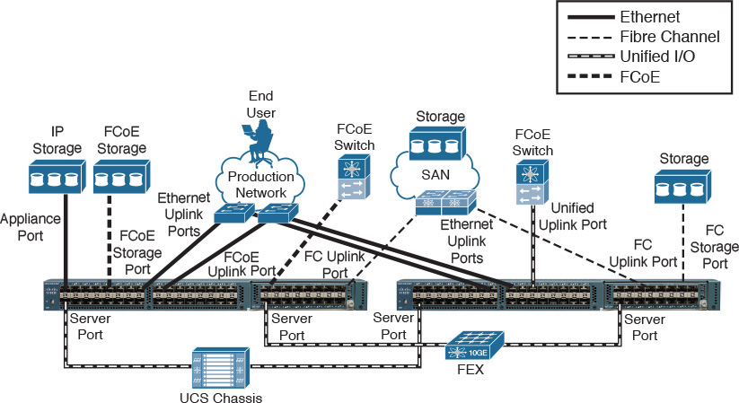
Table 12-4 explains the types of interfaces exhibited in Figure 12-8.

Note
Without loss of generality, this section uses the UCS 6248UP as an example of a Fabric Interconnect. This device can apply the Unified Port concept, where the same interface may be configured in either Ethernet mode or Fibre Channel mode. Because there are other Fabric Interconnect models available in the Cisco UCS portfolio (including UCS-Mini, whose Fabric Interconnect is located inside of a UCS Blade Server Chassis), I will address their specific characteristics in Chapter 13, “Cisco Cloud Infrastructure Portfolio.”
From a Fibre Channel data plane standpoint, each Fabric Interconnect can assume one of the following two modes:
![]() Switch mode: The Fabric Interconnect runs as a traditional Fibre Channel switch, deploying Inter-Switch Links (ISLs) to other switches or directors. Only this mode enables direct connections to Fibre Channel or FCoE storage devices.
Switch mode: The Fabric Interconnect runs as a traditional Fibre Channel switch, deploying Inter-Switch Links (ISLs) to other switches or directors. Only this mode enables direct connections to Fibre Channel or FCoE storage devices.
![]() End-host mode (default): Allows the Fabric Interconnect to act as an HBA to the connected Fibre Channel switch or director, multiplexing all Fibre Channel traffic to F_Ports that can accept multiple FIP Fabric LOGIns (FLOGIs) simultaneously through a feature called N_Port ID Virtualization (NPIV). End-host mode is synonymous with the N_Port Virtualization (NPV) mode discussed in Chapter 8, “Block Storage Technologies.”
End-host mode (default): Allows the Fabric Interconnect to act as an HBA to the connected Fibre Channel switch or director, multiplexing all Fibre Channel traffic to F_Ports that can accept multiple FIP Fabric LOGIns (FLOGIs) simultaneously through a feature called N_Port ID Virtualization (NPIV). End-host mode is synonymous with the N_Port Virtualization (NPV) mode discussed in Chapter 8, “Block Storage Technologies.”
On the other hand, from an Ethernet data plane perspective, each Fabric Interconnect can assume two roles:
![]() Switch mode: The Fabric Interconnect runs as a traditional Ethernet switch, deploying Spanning Tree Protocol (STP) to avoid loops, and sending multidestination traffic (unknown unicast, broadcast, and multicast) to all interfaces that share the VLAN that contains the frame. To completely avoid the drawbacks related to STP, this mode is only recommended if the Fabric Interconnect is directly connected to a router or a Layer 3 switch.
Switch mode: The Fabric Interconnect runs as a traditional Ethernet switch, deploying Spanning Tree Protocol (STP) to avoid loops, and sending multidestination traffic (unknown unicast, broadcast, and multicast) to all interfaces that share the VLAN that contains the frame. To completely avoid the drawbacks related to STP, this mode is only recommended if the Fabric Interconnect is directly connected to a router or a Layer 3 switch.
![]() End-host mode (default): The Fabric Interconnect acts as a host NIC connected to the network, using loop-avoidance techniques very similar to the ones used by virtual switches and, consequently, foregoing the need to run STP. In the case of a Fabric Interconnect, such behavior is achieved through the pinning of each server adapter (which is called vNICs for reasons that will be explored in a future section) in the UCS domain to an Ethernet uplink port or PortChannel. Such pinning can be dynamically established by the Fabric Interconnect or statically determined by the UCS administrator. This mode is recommended when a Layer 2 switch is used upstream to the Fabric Interconnect.
End-host mode (default): The Fabric Interconnect acts as a host NIC connected to the network, using loop-avoidance techniques very similar to the ones used by virtual switches and, consequently, foregoing the need to run STP. In the case of a Fabric Interconnect, such behavior is achieved through the pinning of each server adapter (which is called vNICs for reasons that will be explored in a future section) in the UCS domain to an Ethernet uplink port or PortChannel. Such pinning can be dynamically established by the Fabric Interconnect or statically determined by the UCS administrator. This mode is recommended when a Layer 2 switch is used upstream to the Fabric Interconnect.
UCS Manager
Running within each of the Fabric Interconnects on a cluster, UCS Manager offers server administrators the following capabilities over a UCS domain: server provisioning, device discovery, inventory, configuration, diagnostics, monitoring, fault detection, auditing, and statistics collection.
As you may remember, during basic setup, each Fabric Interconnect is assigned an IP address while sharing a cluster IP address that is entrusted to the primary Fabric Interconnect until it fails for any reason.
Using the cluster IP address, there are multiple ways to access UCS Manager:
![]() Graphical user interface (GUI): Intuitive interface based on a Java desktop application that is downloaded from the primary Fabric Interconnect
Graphical user interface (GUI): Intuitive interface based on a Java desktop application that is downloaded from the primary Fabric Interconnect
![]() Command-line interface (CLI): Command-based interface for configuration using Telnet or Secure Shell (SSH) sessions
Command-line interface (CLI): Command-based interface for configuration using Telnet or Secure Shell (SSH) sessions
![]() Extensible Markup Language Application Programming Interface (XML API): Programmable interface that greatly facilitates the integration of UCS Manager to northbound applications such as cloud orchestrators and automation applications
Extensible Markup Language Application Programming Interface (XML API): Programmable interface that greatly facilitates the integration of UCS Manager to northbound applications such as cloud orchestrators and automation applications
Note
In truth, both the GUI and CLI use the XML API to access UCS Manager as, respectively, an external Java desktop application and an internal CLI session manager.
Due to its superior user experience, the GUI is probably the most popular method of access to UCS Manager. Figure 12-9 shows the results when you access its IP address via a web browser.

Through this page, you can download the UCS Manager GUI application or access the Keyboard, Video, and Mouse (KVM) of any server on this domain. Upon selecting the first option and providing valid credentials, you finally get access to UCS Manager, as Figure 12-10 shows.

Providing a complete guide for the UCS Manager GUI is beyond the scope of this book. You can easily access its online documentation for this purpose. However, to help get you started, the upper-left corner of Figure 12-10 displays how UCS Manager organizes its managed objects and policies, and Table 12-5 summarizes the main administrative operations that can be executed within each of the five main tabs of UCS Manager, as well as the probable infrastructure team that will deal with tasks in each tab.

Tip
On each main tab, it is also possible to select filters that allow a cleaner visualization of a single part of the tab parameters.
As an example, Figure 12-10 shows the default parameters for the Chassis/FEX Discovery Policy. Note that this policy defines that a single link to a Chassis IOM is sufficient for UCS Manager to initialize chassis discovery after a server port is configured and connected to it.
UCS B-Series
As briefly mentioned earlier in this section, UCS B-Series Blade Servers are contained in the UCS B-Series Blade Server Chassis (also known as UCS 5108) to be managed by UCS Manager. At the time of this writing, all B-Series servers are based on Intel Xeon processors.
The external connectivity of the UCS B-Series Blade Chassis is represented in Figure 12-11.
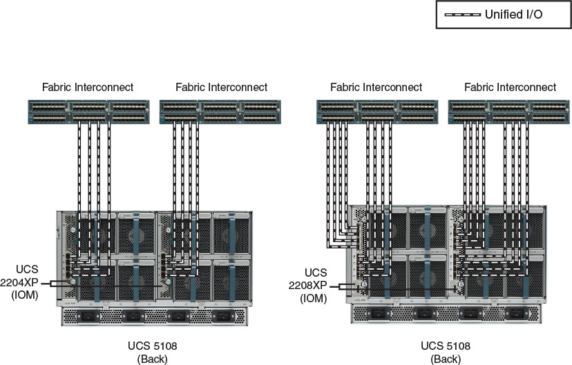
As you can observe in Figure 12-11, a UCS 5108 chassis supports two IOM models, which, at the time of this writing, are UCS 2204XP and 2208XP. Whereas the former allows up to four 10-Gbps connections to a single Fabric Interconnect, the latter supports eight of these connections, offering 80 Gbps of bandwidth to each IOM, and consequently 160 Gbps for the entire chassis.
Tip
By design, you cannot connect an IOM to both Fabric Interconnects.
At heart, these modules are Fabric Extenders whose fabric interfaces are connected to a Fabric Interconnect (performing the role of a parent switch) while their host interfaces are connected to the B-Series I/O adapters through internal electrical chassis connections. Consequently, and in harmony with the UCS consolidation principles, all server ports in a domain are connected to logical interfaces that are called virtual Ethernet (vEthernet) and are dynamically instantiated at each Fabric Interconnect.
After a sufficient number of server ports on a Fabric Interconnect are configured and connected to an IOM (according to the Chassis/FEX Discovery Policy shown previously in Figure 12-10), UCS Manager starts to catalog and control the chassis, IOM, blade servers, and their internal components.
Figure 12-12 depicts the UCS Manager Equipment tab after the discovery process has ended.

Figure 12-12 also lists all blade servers that are installed in the only chassis from this UCS domain. In general, all B-Series server models differ from each other in aspects such as number of CPU sockets, number of memory slots, number of mezzanine slots (or LoM), and number of hard drives. Resultantly, they can assume one of the following formats:
![]() Half-width blade: Consumes one slot from the chassis. Up to eight blades can be inserted into a single UCS 5108.
Half-width blade: Consumes one slot from the chassis. Up to eight blades can be inserted into a single UCS 5108.
![]() Full-width blade: Occupies two slots from the chassis. Up to four blades can be inserted into a single UCS 5108.
Full-width blade: Occupies two slots from the chassis. Up to four blades can be inserted into a single UCS 5108.
![]() Double-full-width blade: Fills four slots from the chassis. Up to two blades can be inserted into UCS 5108.
Double-full-width blade: Fills four slots from the chassis. Up to two blades can be inserted into UCS 5108.
Note
For more details about the available UCS B-Series servers available at the time of this writing, please refer to Appendix A.
Figure 12-13 exposes the internal connectivity of a half-width blade server inserted into a UCS 5108 blade chassis.

Applying your X-ray vision to the chassis shown on the left in Figure 12-13, you can observe the connectivity of the generic half-width blade server on the right. Depending on the type of converged network adapter (CNA) that is inserted into the server, it can deploy one 10-Gbps Unified I/O connection for each 2204XP IOM or four of these connections for each 2208XP IOM. Figure 12-13 depicts the latter scenario, where the half-width server can potentially transmit up to 80 Gbps of converged traffic to the IOM.
Note
As is true for all Nexus 2000 models, both 2204XP and 2208XP introduce an oversubscription rate between internal and external interfaces. In the case of these IOMs, it is 4:1 if all interfaces are used.
Alternatively, Figure 12-14 depicts the internal connectivity of a full-width blade.

Because a B-Series Blade Server actually occupies two chassis slots, it can leverage double the bandwidth resources. Hence, depending on the deployed CNAs, this server can have up to 40 Gbps (2204XP IOM) or 160 Gbps (2208XP). Again, Figure 12-14 depicts the internal connections enabled by a UCS 2208XP IOM.
Fitly, a double-full-width blade server will offer two times more adapters, internal connections, and available bandwidth when compared to a full-width B-Series server.
UCS C-Series
The Cisco UCS C-Series servers are rack-mountable devices that can be added to a UCS domain. Besides having a different format from the UCS B-Series, UCS C-Series servers differ in the following ways as well:
![]() They can work as an independent server.
They can work as an independent server.
![]() They support more PCIe devices.
They support more PCIe devices.
![]() They can hold more internal storage (HDD or SSD).
They can hold more internal storage (HDD or SSD).
From a hardware capacity angle, UCS C-Series servers roughly follow their blade counterparts, offering corresponding models that also vary in number of CPU sockets, number of memory slots, number of PCIe slots, and type and number of hard drives. Accordingly, to accommodate these varying specifications, UCS C-Series servers are presented in models with 1, 2, and 4 rack units (RU).
Note
Again, if you are looking for specific details about the UCS C-Series server models available at the time of this writing, please refer to Chapter 13.
Figure 12-15 demonstrates how a UCS C-Series server can be deployed and managed.

As Figure 12-15 illustrates, UCS C-Series servers can also be inserted into UCS domains using two possible topologies: direct connection to the Fabric Interconnects and single connection to select Nexus 2000 models managed by the Fabric Interconnects. Besides mimicking the structure of UCS Blade Server Chassis for C-Series servers, the single connection topology allows a higher number of rack-mountable servers in the UCS domain when compared to direct connection topologies (whose limit is the number of ports on each Fabric Interconnect).
As also shown in Figure 12-15, a UCS C-Series server can be deployed in standalone mode, being managed through its Cisco Integrated Management Controller (CIMC). In essence, the CIMC is an internal module built into the server motherboard, which is separate from the main server CPU to run Cisco management firmware for the server.
Tip
The CIMC is also present on UCS B-Series. Actually, UCS Manager accesses the CIMC on both B-Series and C-Series to perform configurations on them.
Even in standalone mode, the CIMC helps a server administrator to perform activities such as
![]() Power on, power off, power cycle, reset, and shut down the server
Power on, power off, power cycle, reset, and shut down the server
![]() Configure the server boot order
Configure the server boot order
![]() Operating system installation through a KVM console and virtual media mapping (where a file located at an administrator PC is mapped to a virtual media in the server)
Operating system installation through a KVM console and virtual media mapping (where a file located at an administrator PC is mapped to a virtual media in the server)
![]() Configure network-related settings, including NIC properties, IPv4, VLANs, and network security
Configure network-related settings, including NIC properties, IPv4, VLANs, and network security
![]() Configure communication services, including HTTP, SSH, Intelligent Platform Management Interface (IPMI), and Simple Network Management Protocol (SNMP)
Configure communication services, including HTTP, SSH, Intelligent Platform Management Interface (IPMI), and Simple Network Management Protocol (SNMP)
![]() Update CIMC firmware
Update CIMC firmware
![]() Monitor faults, alarms, and server status
Monitor faults, alarms, and server status
![]() Set time zone and view local time
Set time zone and view local time
![]() Install and activate BIOS firmware
Install and activate BIOS firmware
Figure 12-16 shows a sample screen from the CIMC GUI on a C-Series server.

UCS Virtual Interface Cards
The Cisco UCS portfolio offers a wide range of NICs, HBAs, and CNAs for both UCS B-Series and C-Series. One in particular, the Cisco Virtual Interface Card (VIC) is an innovative adapter virtualization technique to UCS, redefining server connectivity in the process.
Besides offering I/O consolidation in the form of 10- or 40-Gbps redundant connections, a single VIC can create multiple virtual adapters directly in the server expansion bus. And unlike SR-IOV (introduced earlier in a Tip in the section “X86 Microarchitecture”), a server operating system (or hypervisor) can manage a VIC-generated virtual adapter exactly as it manages a standard PCIe device.
Since their first release in 2009, VIC adapters have been offered with different characteristics and internal architectures, which are summarized in Figure 12-17.

Figure 12-17 portrays three distinct VIC designs. The design shown on the left can achieve up to 20 Gbps total through redundant connections to both fabrics (IOMs in the case of B-Series, and to an FEX, Fabric Interconnect, or Unified I/O switch in the case of C-Series). The middle drawing depicts the B-Series modular LAN on Motherboard (mLoM) that deploys up to 40 Gbps by default, and that can be scaled to 80 Gbps with the use of a port expander. Finally, depicted on the right is the VIC design that can achieve an aggregate bandwidth of up to 80 Gbps.
Note
For the sake of reference, I have listed under each of the designs in Figure 12-17 the names of the VIC adapters that correspond to that design. For more details about each adapter, please refer to the UCS online documentation.
If you look closely, Figure 12-17 also reveals that most VIC adapters can create up to 256 virtual adapters, which can be virtual network interface controllers (vNICs) or virtual host bus adapters (vHBAs). However, that raises the question of how a Fabric Interconnect discerns upstream traffic from different virtual adapters from the same VIC. The answer is detailed in Figure 12-18.

As you can observe on the left side of Figure 12-18, a UCS B-Series server equipped with a non-virtualized adapter sends a standard Ethernet frame to the chassis IOM. As a legitimate Fabric Extender, the IOM inserts a VNTag into the frame before forwarding it to the Fabric Interconnect. A virtual interface (vEthernet, as I have previously commented) is automatically instantiated on the Fabric Interconnect to receive traffic (marked with the specific VNTag) from the adapter interface.
On the right side of Figure 12-18, the server VIC actually imposes the VNTag in the upstream Ethernet frames to permit the differentiation of traffic from distinct vNICs on the Fabric Interconnect. In this case, the IOM only forwards the tagged frames to the uplinks. Because the VIC is actually performing the role of a Fabric Extender, the creation of static virtual adapters within a UCS domain is called Adapter Fabric Extender (Adapter FEX).
Furthermore, UCS Fabric Interconnect can also generate dynamic vNICs (DvNICs) on VIC adapters for a special virtual networking technology called Virtual Machine Fabric Extender (VM-FEX). Similarly to standard Fabric Extenders, VM-FEX consolidates the networking infrastructure, enabling configuration, management, and monitoring of virtual and physical connectivity in the same device.
In a server virtualization environment with VM-FEX
![]() Each virtual machine has a dedicated virtual Ethernet interface on the Fabric Interconnect.
Each virtual machine has a dedicated virtual Ethernet interface on the Fabric Interconnect.
![]() All virtual machine traffic is sent straight to this interface on the Fabric Interconnect.
All virtual machine traffic is sent straight to this interface on the Fabric Interconnect.
![]() Software-based switching can be eliminated because the parent switch will handle all VM-related traffic.
Software-based switching can be eliminated because the parent switch will handle all VM-related traffic.
Figure 12-19 represents the VM-FEX architecture.

As shown in Figure 12-19, VM-FEX demands an active management connection with a VM manager such as VMware vCenter. In this context, the UCS Fabric Interconnect is seen as a distributed virtual switch (DVS) on the VM manager, and, similarly to Nexus 1000V, a port profile created on UCS Manager automatically creates a VM connectivity policy on the VM manager (distributed Port Group in VMware vCenter).
If the VM manager assigns the policy to a virtual machine network adapter, the UCS VIC automatically connects a DvNIC to this VM and imposes a unique VNTag on all upstream traffic that will define a virtual Ethernet interface in the Fabric Interconnect.
More interestingly, VM-FEX can work in tandem with hypervisor bypass technologies (such as VMware vSphere DirectPath I/O) to enable more I/O performance for virtual machines. In these scenarios, rather than relying on the hypervisor CPU processing to forward Ethernet frames through a virtual switch, a DvNIC is fully controlled by a virtual machine.
Note
At the time of this writing, VM-FEX is supported with the following hypervisors: VMware ESXi, Microsoft Hyper-V, and Linux KVM. Select Nexus switches (such as Nexus 5600) can also deploy VM-FEX along UCS C-Series Servers equipped with VIC adapters.
In both Adapter FEX and VM-FEX, a UCS VIC can deploy another innovative feature called Fabric Failover for its spawned vNICs. Through this feature, vNICs that are associated to a vEthernet interface on a Fabric Interconnect can automatically migrate to the other Fabric Interconnect in the case of a major connectivity problem (Fabric Interconnect, IOM, or IOM uplink failure).
Fabric Failover is extremely valuable for servers with nonredundant network adapters that can seize the inherent redundancy of dual-fabric UCS domain.
Besides the aforementioned features, newer VIC versions have enabled enhancements such as
![]() VXLAN and NVGRE encapsulation offload from the CPU: To optimize software-based overlay implementations.
VXLAN and NVGRE encapsulation offload from the CPU: To optimize software-based overlay implementations.
![]() User space NIC (usNIC): Improves performance of software applications using Message Passing Interface (MPI) instead of sockets of other communication APIs. For this objective, it uses kernel bypassing, allowing applications to interact directly with a Cisco UCS VIC.
User space NIC (usNIC): Improves performance of software applications using Message Passing Interface (MPI) instead of sockets of other communication APIs. For this objective, it uses kernel bypassing, allowing applications to interact directly with a Cisco UCS VIC.
![]() Remote Direct Memory Access (RDMA) over Converged Ethernet: Also known as RoCE, this feature allows high-bandwidth and low-latency access to other servers without relying on CPU-bound TCP/IP communications. It is especially designed for high-performance computing (HPC) systems and Microsoft SMB version 3.0 environments.
Remote Direct Memory Access (RDMA) over Converged Ethernet: Also known as RoCE, this feature allows high-bandwidth and low-latency access to other servers without relying on CPU-bound TCP/IP communications. It is especially designed for high-performance computing (HPC) systems and Microsoft SMB version 3.0 environments.
UCS Server Identity
With so many innovations and optimization features, one could easily surmise that server provisioning in the Unified Computing System is a harder task compared to traditional servers. To the contrary, as you will learn in this section, both the UCS architecture and policy model sensibly reduce the amount of repetitive work that is usually associated with the activation of a physical machine.
The apex of the server provisioning process in a UCS system is a logical construct called a service profile, which primarily groups the huge number of server configuration tasks into a single assignment, including several activities that are usually handled by non-server teams. And because a server profile is centrally stored inside UCS Manager, it can be easily associated to server hardware that belongs to a UCS domain.
In truth, any UCS B-Series or C-Series server on a UCS domain must have a service profile associated to it before it is allowed to run an operating system or hypervisor. According to the UCS provisioning model, each server on a UCS domain can only be associated to a single service profile, and in the case of a service profile disassociation, all configurations on a server are reset to its defaults.
From an administrative standpoint, all server configurations and changes are directly executed on the service profile, which works as a “personality” inserted into server hardware. When a service profile is associated with a server, both Fabric Interconnects and server components (such as adapters and BIOS) are configured according to the profile definitions.
Figure 12-20 illustrates how some of these configurations are carried out during the association of a service profile to a UCS B-Series Blade Server.

The association of service profiles is performed as a simple, single operation that only takes a few minutes to complete. A striking difference from traditional server provisioning is that service profiles allow the infrastructure domain tasks to be completed before a server is even purchased. With service profiles, the data center infrastructure can be proactively prepared using definitions from a service profile, which can be promptly associated as soon as hardware is available.
Building a Service Profile
A service profile can be built through the UCS Manager GUI, CLI, or XML API. Choosing the GUI option will enable you to understand more easily the main parameters involved with the configuration of this UCS logical construct, so this section presents that option for building a service profile.
Access UCS Manager as described earlier and select the Servers main tab, as shown in Figure 12-21. Its toolbar and a work pane are displayed to allow you to perform many actions related to service profiles and observe their results.

One of the most usual ways to create a service profile is the Create Service Profile (expert) wizard, whose activation link is highlighted in Figure 12-21. This wizard has ten steps, which are summarized in Table 12-6.
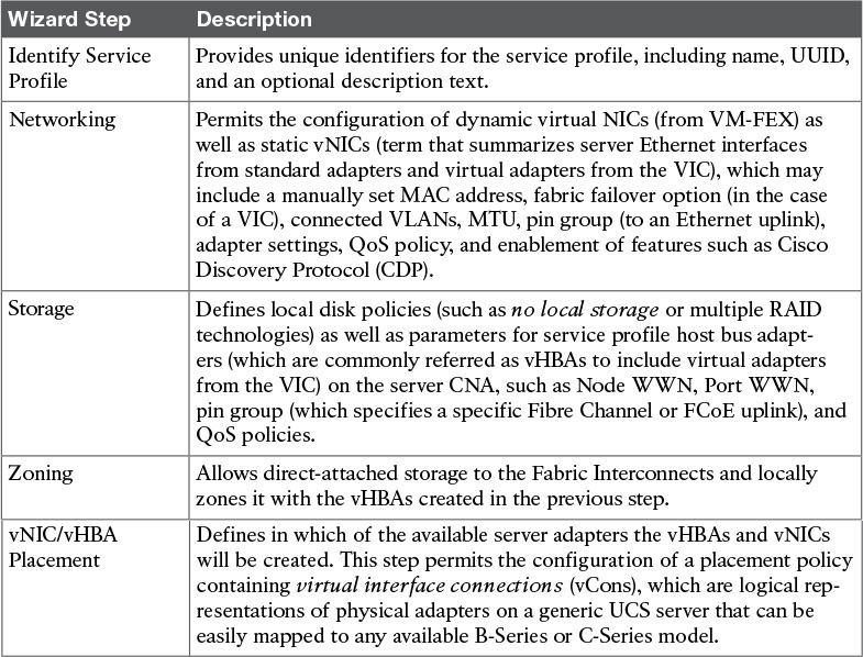

Figure 12-22 shows the result of performing all the wizard steps to create a service profile example called SP-1.
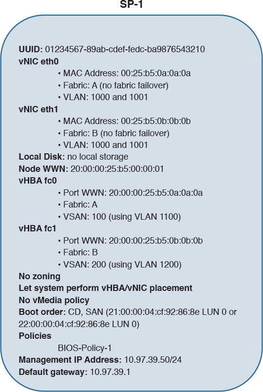
In SP-1, I have configured two vHBAs (fc0 and fc1), two vNICs (eth0 and eth1), static identifiers (UUID, WWNs, MAC and IP addresses), a specific boot order, and a single BIOS policy (which activates Intel HT and Intel VT technologies regardless of the default settings of a server).
Figure 12-23 shows how SP-1 is represented in UCS Manager.

Figure 12-23 demonstrates that SP-1 is located at organization root, but other suborganizations can also be created to permit better control of service profiles per UCS administrator. As SP-1 is not yet associated to any server in the domain, you can perform this action through the Change Service Profile Association link highlighted in the figure.
Note
The service profile association process (and all the configurations defined in it) is actually executed through an operating system called Cisco UCS Utility OS (UUOS), which loads its boot image through PXE in a dedicated VLAN (4047).
Because SP-1 does not possess any local storage, its boot order instructs its associated server to:
1. Try to boot through a CD/DVD-ROM media inserted on the server driver.
2. If a CD/DVD-ROM installation file is not available, try to boot through LUN 0 located at pWWN 21:00:00:04:cf:92:86:8e and reachable through vHBA fc0 in VSAN 100.
3. If this LUN is not available either, try to boot through LUN 0 located on pWWN 22:00:00:04:cf:92:86:8e and reachable through vHBA fc1 in VSAN 200.
Using a virtual media mapping, you can map an operating system installation file in your desktop to the CD/DVD driver on the associated service profile. As SP-1 is initialized, its associated server executes the remote installation file and saves the boot files in the SAN-accessible LUN. From this moment on, the server associated with SP-1 will always use the LUN to boot itself (as long as there is not a mapped file in its CD/DVD driver).
Because remote booting provides the basis for stateless computing, you can easily disassociate SP-1 from the blade to another server on the domain with minimal disruption (only intervals for disassociation, new association, and server boot).
Multiple use cases can be applied for stateless computing on UCS, including server reallocation after major hardware failures or hardware resource exhaustion.
Policies
Cisco UCS leverages policies to reinforce standardization and avoid the mind-numbing repetition of tasks that is usually associated with traditional server provisioning. In a nutshell, a UCS policy defines how UCS components behave in specific situations. In the context of service profiles, UCS policies enclose a set of configurations that can be shared among multiple profiles.
In SP-1, I have configured a single policy, BIOS-Policy-1, that essentially enforces the activation of features from Intel processors that optimize virtualization hosts (Intel HT and VT). Because BIOS-Policy-1 is a reusable policy, it can greatly simplify the creation of new service profiles. As an example, other Create Service Profile (expert) wizard interactions can easily refer to the aforementioned policies to define service profiles with the same processor settings.
Understandably, the complete list of UCS policies is more than enough to fill an entire publication and thus is beyond the scope of this writing. To give you a sampling, allow me to present select UCS policies that can be useful to streamline and standardize the creation of service profiles:
![]() Adapter policy: Regulates how an adapter handles traffic and acts in a host. It may include queue configuration parameters, performance enhancements, and failover behavior (in the case of vNICs generated on VICs).
Adapter policy: Regulates how an adapter handles traffic and acts in a host. It may include queue configuration parameters, performance enhancements, and failover behavior (in the case of vNICs generated on VICs).
![]() BIOS policy: As previously commented, a BIOS policy automates the configuration of BIOS settings for a server or group of servers. It includes general settings (such as reboot on BIOS settings change and quiet boot), processor configurations (such as the aforementioned Intel HT and VT), Intel Directed IO, RAS memory, serial port, USB, PCI configuration, additional boot options, and other server management details.
BIOS policy: As previously commented, a BIOS policy automates the configuration of BIOS settings for a server or group of servers. It includes general settings (such as reboot on BIOS settings change and quiet boot), processor configurations (such as the aforementioned Intel HT and VT), Intel Directed IO, RAS memory, serial port, USB, PCI configuration, additional boot options, and other server management details.
![]() Boot policy: Defines the boot order for a server or group of servers. It may include local boot devices (such as a local disk or CD-ROM) or remote boot devices (including SAN or LAN via PXE).
Boot policy: Defines the boot order for a server or group of servers. It may include local boot devices (such as a local disk or CD-ROM) or remote boot devices (including SAN or LAN via PXE).
![]() Local disk configuration policy: Configures local hard disk drives on a server through its storage controller. It can assign the following modes to local disks: no local storage, RAID 0 Striped, RAID 1 Mirrored, any configuration (does not change the current configuration on the server local disk), no RAID, RAID 5 Striped Parity, RAID 6 Striped Dual Parity, RAID 10 Mirrored and Striped, among others.
Local disk configuration policy: Configures local hard disk drives on a server through its storage controller. It can assign the following modes to local disks: no local storage, RAID 0 Striped, RAID 1 Mirrored, any configuration (does not change the current configuration on the server local disk), no RAID, RAID 5 Striped Parity, RAID 6 Striped Dual Parity, RAID 10 Mirrored and Striped, among others.
![]() Power control policy: Establishes priorities for blade servers in a UCS domain. If all blades are active and reach a predefined power cap, service profiles with higher priority will take precedence over service profiles with lower priority.
Power control policy: Establishes priorities for blade servers in a UCS domain. If all blades are active and reach a predefined power cap, service profiles with higher priority will take precedence over service profiles with lower priority.
![]() Scrub policy: Determines what happens to local data and to the BIOS settings on a server when it is disassociated from this service profile. In summary, if Disk Scrub is enabled, all data on any local drives is destroyed (otherwise it is preserved). On the other hand, if BIOS Scrub is enabled, it erases all BIOS settings for the server and resets them to the BIOS defaults for that server type and vendor.
Scrub policy: Determines what happens to local data and to the BIOS settings on a server when it is disassociated from this service profile. In summary, if Disk Scrub is enabled, all data on any local drives is destroyed (otherwise it is preserved). On the other hand, if BIOS Scrub is enabled, it erases all BIOS settings for the server and resets them to the BIOS defaults for that server type and vendor.
![]() Serial over LAN policy: Controls how the input and output of a UCS serial port can be redirected to an SSH session. It includes Serial over LAN state enablement and speed in bauds.
Serial over LAN policy: Controls how the input and output of a UCS serial port can be redirected to an SSH session. It includes Serial over LAN state enablement and speed in bauds.
Besides facilitating server provisioning, UCS policies also enable the efficient management of servers that are already activated. Because policies are “live” objects on a UCS domain, a change on any of them may be automatically replicated to all service profiles that are using such a policy (depending on their configured maintenance policy).
Cloning
Service profile cloning severely decreases the number of tasks to create service profiles. In UCS Manager, after selecting a service profile, the Create a Clone link (also shown in Figure 12-22) will only request a profile name before creating an approximated copy of this service profile.
Generally, a service profile clone usually requires additional changes before it can be associated to a UCS blade or rack-mount server. To fully understand this statement, please review Figure 12-24, which compares the configurations of SP-1 and its clone, SP-1-Clone.

In Figure 12-24, observe that whereas the cloning procedure reuses all configurations and policies from its parent service profile, it obviously cannot replicate SP-1’s unique identifiers (UUID, WWNs, MACs, and management IP address). As a consequence, UCS Manager derives most identifiers for service profile clones from the server hardware.
When such action is not possible, UCS Manager picks the identifiers from default pools, the subject of the next section.
Pools
The allocation of unique identifiers to assorted service profiles can be automated through the use of pools. In general, UCS identity pools are defined as collections of physical or logical identities that can be assigned to UCS domain resources.
As a clarification of this concept in UCS, I have created the following pools (with 31 identifiers each):
![]() UUID-Pool: UUIDs from 01234567-89AB-CDEF-0000-000000000001 to 01234567-89AB-CDEF-0000-00000000001F
UUID-Pool: UUIDs from 01234567-89AB-CDEF-0000-000000000001 to 01234567-89AB-CDEF-0000-00000000001F
![]() MAC-Pool-A: MAC addresses from 0025.b500.0a01 to 0025.b500.0a1f
MAC-Pool-A: MAC addresses from 0025.b500.0a01 to 0025.b500.0a1f
![]() MAC-Pool-B: MAC addresses from 0025.b500.0b01 to 0025.b500.0b1f
MAC-Pool-B: MAC addresses from 0025.b500.0b01 to 0025.b500.0b1f
![]() nWWN-Pool: Node WWNs from 20:00:00:25:b5:00:01:01 to 20:00:00:25:b5:00:01:1f
nWWN-Pool: Node WWNs from 20:00:00:25:b5:00:01:01 to 20:00:00:25:b5:00:01:1f
![]() pWWN-Pool-A: Port WWNs from 20:00:00:25:b5:00:0a:01 to 20:00:00:25:b5:00:0a:1f
pWWN-Pool-A: Port WWNs from 20:00:00:25:b5:00:0a:01 to 20:00:00:25:b5:00:0a:1f
![]() pWWN-Pool-B: Port WWNs from 20:00:00:25:b5:00:0b:01 to 20:00:00:25:b5:00:0b:1f
pWWN-Pool-B: Port WWNs from 20:00:00:25:b5:00:0b:01 to 20:00:00:25:b5:00:0b:1f
![]() Management IP Pool: IP addresses from 10.97.39.81 to 10.97.39.122 (with mask 255.255.255.0 and default gateway 10.97.39.1)
Management IP Pool: IP addresses from 10.97.39.81 to 10.97.39.122 (with mask 255.255.255.0 and default gateway 10.97.39.1)
The configuration of pools is distributed across the UCS Manager GUI main tabs. Thus, I created the aforementioned pools on the Servers (UUID-Pool), SAN (nWWN-Pool, pWWN-Pool-A, and pWWN-Pool-B), and LAN (MAC-Pool-A, MAC-Pool-B, and Management IP Pool) main tabs.
When a UCS administrator applies these logical constructs to a service profile instead of manually assigning identifiers, UCS Manager automatically chooses one of the available addresses for this profile, relieving the administrator from the menial tasks related to address management.
When all of these pools are referred in SP-1-Clone, this service profile will use the values shown in Figure 12-25.

Tip
By default, UCS Manager uses descending order to distribute the elements of a pool.
Pools are not restricted to identifiers in a UCS domain. A server pool can be defined as a dynamic selection of servers from a UCS domain that share common characteristics (such as minimum memory size or local storage characteristics) or are manually grouped together. Using server pools, UCS Manager can automatically associate a service profile to a server that meets predefined specifications using a server pool policy qualification.
Besides memory type and storage configuration, these policies can qualify servers according to their adapter type, chassis location, CPU characteristics (cores, type, and configuration), and server model.
Templates
Although service profile cloning allows you to quickly create a handful of service profiles, a UCS domain can only achieve the highest level of automation through the use of templates.
A service profile template can be defined as a UCS logical construct that groups policies, identity pools, and other definitions (such as the number of vNICs and vHBAs) and that can promptly spawn multiple service profiles sharing the same characteristics but using distinct identifiers.
As shown earlier in Figure 12-22, the UCS Manager GUI has a Create Service Profile Template wizard, which allows a step-by-step configuration of a service profile template with a very similar structure to the Create Service Profile (expert) wizard. Table 12-7 describes the steps of the Create Service Profile Template wizard, with special emphasis on the difference between the two wizard procedures.


Note
As a general note, an identifier on a service profile template is usually assigned to an address pool or derived from the hardware associated with its service profiles. Consequently, if you want to deploy stateless computing with service profile templates, using pools is mandatory.
As an example, Figure 12-26 represents all the elements that are involved with the creation of a service profile template called SP-Template-1.

In addition to creating vNIC and vHBA templates and reusing BIOS-Policy-1, I have created and assigned the following policies to SP-Template-1:
![]() Disk-Policy-1: No local storage
Disk-Policy-1: No local storage
![]() vCON-Policy-1: Places vNICs and vHBAs in the available adapters using the round-robin algorithm
vCON-Policy-1: Places vNICs and vHBAs in the available adapters using the round-robin algorithm
![]() Boot-Policy-1: CD-ROM and SAN boot (21:00:00:04:cf:92:86:8e LUN 0 or 22:00:00:04:cf:92:86:8e LUN 0)
Boot-Policy-1: CD-ROM and SAN boot (21:00:00:04:cf:92:86:8e LUN 0 or 22:00:00:04:cf:92:86:8e LUN 0)
With this service profile template, it is extremely easy to create service profiles from it. Figure 12-27 shows how it can be done in the UCS Manager GUI.
On the template General tab, by selecting Create Service Profile from Template and then defining prefix FromTemplate-SP-, I have hastily created two service profiles called FromTemplate-SP-1 and FromTemplate-SP-2. Figure 12-28 represents the configurations that are found on both spawned service profiles.


Because Template-1 belongs to the organization root, both service profiles are automatically included in the same organization. However, a UCS administrator can redirect the service profiles created from SP-Template-1 to a suborganization to implement tenant-based administration restrictions.
Finally, it is worth remembering that SP-Template-1 was configured as an updating template. Therefore, if a UCS administrator changes a parameter in SP-Template-1, service profiles FromTemplate-SP-1 and FromTemplate-SP-2 will automatically be updated according to the template maintenance policy.
UCS Central
As a direct consequence of the traction Cisco Unified Computing System quickly gained in the server market, many IT administrators began to wonder how the configuration and monitoring of multiple UCS domains could be further optimized. In 2012, Cisco answered this inquiry with UCS Central, software that fills the “manager of managers” role in the UCS architecture.
Deployed as a virtual appliance (for VMware vSphere and Microsoft Hyper-V), UCS Central provides a centralized control panel for multiple UCS domains, according to the relationship shown in Figure 12-29.

As Figure 12-29 demonstrates, UCS Central provides a focal point of management for potentially geographically separated UCS domains, while enforcing policy compliance across such domains to help ensure consistency and standardization. Also pulling information from its managed domains, UCS Central consolidates the following:
![]() Inventory, health status, faults from all UCS components
Inventory, health status, faults from all UCS components
![]() Keyboard, Video, and Mouse (KVM) access to any server
Keyboard, Video, and Mouse (KVM) access to any server
![]() Control of identifier pools, such as UUID, WWNs, and MACs, to avoid conflicts
Control of identifier pools, such as UUID, WWNs, and MACs, to avoid conflicts
![]() Global policies such as service profiles and templates
Global policies such as service profiles and templates
![]() UCS backup scheduling
UCS backup scheduling
![]() Policy-based firmware upgrades
Policy-based firmware upgrades
![]() Bandwidth, power, and thermal statistics collections with up to one year of historical data.
Bandwidth, power, and thermal statistics collections with up to one year of historical data.
UCS Central has a GUI that is akin to the UCS Manager GUI, as shown in Figure 12-30.

Notice in Figure 12-30 that UCS Central enables you to create domain groups, which can offer specific policies and configurations for multiple UCS domains. In the scenario depicted in the figure, the domain group New_York contains at least two UCS domains (UCSM1 and UCSM2).
Part of what UCS Central configures in a domain can be decided in UCS Manager. As an illustration, Figure 12-31 exhibits the UCS Central registration view in UCS Manager.
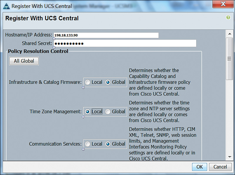
As you can observe in Figure 12-31, a UCS Manager instance can delegate all possible policy configurations to UCS Central (Global) or only a select group of them (Local). In this example, the UCS domain administrator has decided that Time Zone Management will be performed locally, while Infrastructure & Catalog Firmware and Communication Services policies will be fully controlled by UCS Central.
Conveniently, UCS Central also offers an XML API that greatly facilitates the automation of up to 6000 managed UCS servers (at the time of this writing).
Cloud Computing and UCS
As a savvy reader, you’ve already noticed some similarities between Unified Computing System and Application Centric Infrastructure (ACI), the Cisco SDN solution discussed in Chapter 11, “Network Architectures for the Data Center: SDN and ACI.” Although UCS predates ACI by four years, both solutions share the principles of a policy-driven infrastructure as the most effective way to bring automation to data centers.
Furthermore, both architectures also integrate physical infrastructure provisioning, which is handily omitted in some infrastructure virtualization solutions. Through simple abstractions and efficient policy models, UCS and ACI can provide the consistency and standardization that are required for cloud computing scenarios.
Note
Whereas Cisco ACI can be viewed as a network managed by servers (APIC), UCS can be viewed as a group of servers managed by switches (Fabric Interconnects). Coincidences are indeed plans in disguise.
But how does UCS actually contribute to cloud computing deployments? The answer, of course, relates to the importance of physical servers in these scenarios. And, as with many other infrastructure technologies explained in previous chapters, physical servers can serve cloud implementations in two contexts:
![]() Infrastructure: Physical machines literally embody the pool of computing resources that must be quickly provisioned as tenant virtual resources are deployed.
Infrastructure: Physical machines literally embody the pool of computing resources that must be quickly provisioned as tenant virtual resources are deployed.
![]() Bare Metal as a Service: In some scenarios, cloud tenants may want to deploy physical servers for special applications such as HPC clusters, database systems, big data, and (please brace yourself for yet another metaphysical concept) cloud infrastructure as a service, which can provide a complete cloud environment that will be managed by an end user.
Bare Metal as a Service: In some scenarios, cloud tenants may want to deploy physical servers for special applications such as HPC clusters, database systems, big data, and (please brace yourself for yet another metaphysical concept) cloud infrastructure as a service, which can provide a complete cloud environment that will be managed by an end user.
As depicted in Figure 12-32, UCS and its basic provisioning principles are very suitable for any of these cloud computing scenarios.

As shown in Figure 12-32, to respond to cloud tenant requests via the portal, the UCS architecture can support the following events:
![]() The cloud orchestrator determines the need to provision three new servers (to provide more server resources for hypervisors or deploy a bare-metal environment).
The cloud orchestrator determines the need to provision three new servers (to provide more server resources for hypervisors or deploy a bare-metal environment).
![]() The orchestrator selects the most appropriate service profile template to serve its objective and, leveraging the UCS Manager XML API, requests three service profile instances from this template.
The orchestrator selects the most appropriate service profile template to serve its objective and, leveraging the UCS Manager XML API, requests three service profile instances from this template.
![]() Immediately after the service profiles are created, they can be dynamically associated to servers on a pool that is assigned to the service profile template.
Immediately after the service profiles are created, they can be dynamically associated to servers on a pool that is assigned to the service profile template.
The decommission process could also occur in a similar manner. Moreover, UCS Central could potentially be used in such a scenario, providing a strategically centralized point of management for all unified computing resources in a cloud-oriented data center facility.
Hence, due to its policy model, UCS natively offers automation capabilities that drastically simplify the orchestration workflows in the cloud software stack.
Around the Corner: OpenStack Ironic
The OpenStack Ironic project intends to provision physical hardware as opposed to virtual machines. With its goal of replacing all bare-metal drivers that were originally developed for the Nova project, Ironic can be understood as a physical machine manager on OpenStack implementations.
Named Ironic as a double-meaning pun (iron as a metal and the irony that OpenStack was very focused on virtual machines), the project uses open protocols such as PXE, Dynamic Host Configuration Protocol (DHCP), Network Bootstrap Program (NBP), Trivial FTP (TFTP), and IPMI to control hardware resources. However, it also supports the development of vendor-specific drivers to incorporate specific features from server architectures such as Cisco UCS.
Because Cisco has been extremely participative in the integration of its products to the OpenStack project, UCS already offers the following integrations for Ironic deployments:
![]() Ironic can boot a Glance image onto a UCS Manager-managed bare-metal server through PXE.
Ironic can boot a Glance image onto a UCS Manager-managed bare-metal server through PXE.
![]() An OpenStack cloud can power on and off a server within a UCS domain without relying on IPMI.
An OpenStack cloud can power on and off a server within a UCS domain without relying on IPMI.
![]() The capability to report hardware statistics to Ceilometer, which is the OpenStack module responsible for metering and monitoring.
The capability to report hardware statistics to Ceilometer, which is the OpenStack module responsible for metering and monitoring.
Just like Nova, Ironic must interact with various OpenStack services such as Glance, Neutron, Cinder, and others to access the resources required to automatically provision a bare-metal machine instance.
Further Reading
![]() OpenStack Ironic: https://wiki.openstack.org/wiki/Ironic
OpenStack Ironic: https://wiki.openstack.org/wiki/Ironic
![]() OpenStack Ironic integration with Cisco UCS B/C-Series servers: https://github.com/CiscoUcs/Ironic-UCS
OpenStack Ironic integration with Cisco UCS B/C-Series servers: https://github.com/CiscoUcs/Ironic-UCS
Exam Preparation Tasks
Review All the Key Topics
Review the most important topics in this chapter, denoted with a Key Topic icon in the outer margin of the page. Table 12-8 lists a reference of these key topics and the page number on which each is found.

Table 12-8 Key Topics for Chapter 12
Complete the Tables and Lists from Memory
Print a copy of Appendix B, “Memory Tables” (found on the CD), or at least the section for this chapter, and complete the tables and lists from memory. Appendix C, “Answers to Memory Tables,” also on the CD, includes completed tables and lists so that you can check your work.
Define Key Terms
Define the following key terms from this chapter, and check your answers in the glossary:
single-root I/O virtualization (SR-IOV)
basic input/output system (BIOS)
Cisco Integrated Management Controller (CIMC)
virtual network interface controller (vNIC)
virtual host bus adapter (vHBA)
Adapter Fabric Extender (Adapter FEX)