
Chapter 4. Behind the Curtain
This chapter covers the following topics:
![]() Cloud Infrastructure: Journey to the Cloud
Cloud Infrastructure: Journey to the Cloud
![]() Application Programming Interfaces
Application Programming Interfaces
Taking a quick glance at our rearview mirror, up to this point in the book we have approached cloud computing from an external perspective, focusing on the relationship between cloud consumers and cloud resources. Throughout the previous three chapters, I have discussed the essential aspects that commonly characterize cloud computing environments and explored different classifications according to the types of offered services and restrictions of use.
In this chapter, we shift gears to investigate how exactly a cloud deployment works. Here, you will learn about the components and concepts a cloud architect should master before effectively designing such an environment.
Although the CLDFND exam does not explicitly demand knowledge about the topics discussed in this chapter, I have written it strategically to bridge the gap between the lofty expectations of a cloud computing implementation and the realities of its operation on service providers, enterprise, and public organizations.
With such intention, the chapter covers the basic architecture of a cloud deployment and its main software functions; data center infrastructure evolution toward cloud computing; and the main methods of communication between all cloud elements. And to further assist you to successfully cross the chasm between a cloud user and a cloud professional, your reading experience will be broadened through real-world solutions and scenarios.
“Do I Know This Already?” Quiz
The “Do I Know This Already?” quiz allows you to assess whether you should read this entire chapter thoroughly or jump to the “Exam Preparation Tasks” section. If you are in doubt about your answers to these questions or your own assessment of your knowledge of the topics, read the entire chapter. Table 4-1 lists the major headings in this chapter and their corresponding “Do I Know This Already?” quiz questions. You can find the answers in Appendix A, “Answers to Pre-Assessments and Quizzes.”

1. Which of the following are components of the cloud software stack? (Choose all that apply.)
a. Virtualization software
b. Meter
c. Orchestrator
d. Portal
e. All software running within a data center that is hosting a cloud environment
2. Which of the following options summarizes the importance of standardization for cloud deployments?
a. Any cloud computing deployment requires a single vendor for all infrastructure components.
b. Virtualization solutions do not require standardization in cloud computing implementations.
c. Cloud software stack solutions already provide standardization for cloud infrastructure.
d. Standardization of hardware, software, processes, and offerings facilitate automation and increase predictability in a cloud computing deployment.
e. None, because cloud computing scenarios must always be ready for customization.
3. Which of the following are not characteristics of RESTful application programming interfaces? (Choose all that apply.)
a. Uses HTTP or HTTPS
b. Only supports XML data
c. Designed for web services
d. Follows a request-response model
e. Designed for human reading
Foundation Topics
Cloud Computing Architecture
Let’s begin with a brief review of the first three chapters. Chapter 1, “What Is Cloud Computing?” introduced you to fundamental concepts that frame cloud computing, with strong emphasis given to the essential characteristics all cloud environments share, as defined by NIST: on-demand self-service, broad network access, resource pooling, rapid elasticity, and measured service. In Chapters 2 and 3, “Cloud Shapes: Service Models,” and “Cloud Heights: Deployment Models,” respectively, you learned about two autonomous classifications of cloud computing:
![]() Service models: Cloud service offerings are classified according to their level of customization flexibility and readiness to support consumer needs: Infrastructure as a Service (IaaS), Platform as a Service (PaaS), and Software as a Service (SaaS).
Service models: Cloud service offerings are classified according to their level of customization flexibility and readiness to support consumer needs: Infrastructure as a Service (IaaS), Platform as a Service (PaaS), and Software as a Service (SaaS).
![]() Deployment models: Cloud computing environments are classified according to the number of different organizations that can access their services: public, private, community, and hybrid clouds.
Deployment models: Cloud computing environments are classified according to the number of different organizations that can access their services: public, private, community, and hybrid clouds.
As a CCNA Cloud candidate, you now have a good grasp of all the high-level concepts that you are expected to know for the exam. But as a future cloud practitioner, I imagine you must have asked several times throughout your reading: What lies behind the curtain of such wizardry? And to tell you the truth, it was kind of grueling for this engineer to avoid deployment details in order to distill the conceptual essence of cloud computing.
Fortunately, it is time to delve into the details of how these special IT environments actually operate. To begin with, Figure 4-1 displays a generic architecture that highlights important components that are present in the large majority of cloud computing deployments.

In Figure 4-1, the cloud elements are clearly separated into two groups: cloud software stack and cloud infrastructure. Such division is further described in Table 4-2.


Whereas the components of the cloud software stack translate the consumer requests into infrastructure management operations, the cloud infrastructure elements embody the resources that will actually be used by the cloud consumers. As represented in Figure 4-1, the cloud infrastructure consists of network devices, storage systems, physical servers, virtual machines, security solutions, networking service appliances, and operating systems, among other solutions.
Because each of these infrastructure elements will be thoroughly explained in future chapters, the following sections describe the main components of the cloud software stack.
Note
Across different cloud computing deployments, you will certainly find these elements implemented in varied arrangements, such as services of monolithic applications or as integrated software modules from different vendors. The focus of this chapter is to introduce these elements as functions rather than as independent software pieces.
Cloud Portal
Much like an application on a personal computer, the cloud portal directly interacts with end users. Essentially, the portal publishes cloud service catalogs, wizards for guided user “shopping,” interactive forms, approval workflows, status updates, usage information, and billing balances.
Figure 4-2 depicts an example screenshot from the Cisco Prime Service Catalog (PSC) cloud portal, which is a software module that belongs to the Cisco ONE Enterprise Cloud Suite integrated cloud software stack. As indicated, the interface is presented to the user as a personal IT as a Service (ITaaS) storefront.

In Figure 4-2, a cloud end user has access to different catalogs, including non-cloud device and desktop application-related services. After selecting the Private Cloud IaaS option in the lower-right corner, the cloud user is presented with the available cloud service offerings, six of which in this particular example are displayed in Figure 4-3.

Regardless of what is actually being offered (for now, you do not have to worry about the terms in the service names), it is important to notice that this catalog may have been specially customized for this user, a group he belongs to, or his organization.
Tip
The term “secure container” describing five of the services in Figure 4-3 technically refers to virtual application containers, which can be understood as isolated application environments that usually contain exclusive virtual elements such as VLANs, VXLANs, virtual machines, and virtual networking services. Chapter 7, “Virtual Networking Services and Application Containers,” will discuss this concept in much more detail.
Most cloud portals also provide administrative tools to foster customization and facilitate integration with other cloud software stack modules. To illustrate these operations, Figure 4-4 depicts some of the options available to a PSC administrative account creatively called admin.

Through such a portal, cloud portal administrators can also monitor the cloud status, control user orders, and create new service offerings for cloud users. Figure 4-5 illustrates the latter, through the Prime Service Catalog tool called Stack Designer.

Figure 4-5 depicts the creation of a new service called “CCNA Cloud CLDFND Exam Simulator,” which contains two servers: an app server running the exam simulator, and a db server containing multiple questions that can be summoned to compose an on-demand exam.
The PSC software stack designer uses templates with a varied number of elements (virtual machines, for example) to enable an easy assignment of applications to each catalog offering. After the application is designed, it can be published to the cloud end users as Figure 4-6 shows.

The various tabs of the interface shown in Figure 4-6 enable a cloud portal administrator to configure all parameters related to publishing a service catalog, including the name, associated logo, description, and authorized users. In this specific screen capture, the CCNA Cloud CLDFND Exam Simulator application will be available to all users (“Grant access to Anyone”).
Figure 4-7 represents the updated Private Cloud IaaS catalog after the portal administrator successfully publishes the recently designed service.

Broadly speaking, an effective cloud portal solution should
![]() Primarily provide a good experience for end users’ operations
Primarily provide a good experience for end users’ operations
![]() Offer useful tools for service customization and administrative tasks
Offer useful tools for service customization and administrative tasks
![]() Facilitate the integration with other components of the cloud software stack
Facilitate the integration with other components of the cloud software stack
Cloud Orchestrator
Drawing again on the comparison between the components of a cloud software stack and those of a PC software stack, a cloud orchestrator correlates to a computer operating system. Much like an operating system orchestrates PC hardware resources to fulfill user application tasks, a cloud orchestrator coordinates infrastructure resources according to user requests issued on the portal.
The orchestrator epitomizes the core of a cloud computing deployment because it must interoperate with all cloud elements, from both the cloud software stack and the cloud infrastructure.
As demonstrated in the last section, when a cloud portal administrator is designing a service to be published to end users, she leverages options that individually represent infrastructure requests that will be issued to the cloud orchestrator whenever a user solicits this service. From the orchestrator standpoint, each of these requests refers to the execution of a predefined workflow, which is expressed as a sequence of tasks that is organized to be carried out in order in a fast and standardized way.
Figure 4-8 portrays a single workflow from the embedded cloud orchestrator in Cisco ONE Enterprise Cloud Suite: the Cisco Unified Computing System Director (or simply, UCS Director).

In Figure 4-8, a workflow called “Fenced Container Setup – dCloud” is detailed as a sequential set of tasks representing the atomic operations that are executed on a single device. As is true of any UCS Director workflow, Fenced Container Setup – dCloud begins with a Start task, which obviously symbolizes the first step of the workflow. In this specific scenario, Start has an arrow pointing to task “2620. AllocateContainerVMResources_1095,” which must be executed according to parameters transmitted by the cloud portal. If task 2620 is executed correctly, the cloud orchestrator carries out the next task (2621. ProvisionContainer-Network_1096), and so forth. Should any error occur, the workflow is programmed to forward the execution to an error task (generating a warning message to the cloud orchestrator administrator, for example).
Because this workflow was actually invoked when an end user solicited a CCNA Cloud CLDFND Exam Simulator instantiation, a cloud orchestrator administrator can also monitor the portal service request execution, as Figure 4-9 demonstrates.

To correctly execute a workflow, a cloud orchestrator must have information about the devices that are related to each workflow task. Using management connections for this endeavor, UCS Director also monitors resource usage and availability, greatly simplifying capacity planning of a cloud computing environment.
Figure 4-10 depicts a dashboard from UCS Director displaying device information, provisioned resources, and overall capacity for storage (na-edge1), servers (dCloud_UCSM), network (VSM), and server virtualization (dCloud_VC_55).

Through the monitoring information shown in Figure 4-10, UCS Director can inform the cloud portal whenever there is resource saturation.
In a nutshell, an efficient orchestration solution must always combine simplicity with flexibility in a balanced way. It must be easy enough to attract adoption, customizable to execute very sophisticated operations, and allow open source development to leverage code reuse for both tasks and workflows.
Cloud Meter
A cloud meter is the cloud software stack module that concretizes service measurement in a cloud computing deployment. As end users request resources in the cloud portal, the cloud meter does the following:
![]() Receives notifications from the cloud orchestrator informing when infrastructure resources were provisioned for the cloud consumer, their usage details, and the exact time they were decommissioned
Receives notifications from the cloud orchestrator informing when infrastructure resources were provisioned for the cloud consumer, their usage details, and the exact time they were decommissioned
![]() Supports the creation of billing plans to correlate cloud resource usage records, time period, and user identity to actual monetary units
Supports the creation of billing plans to correlate cloud resource usage records, time period, and user identity to actual monetary units
![]() Summarizes received information, eliminates errors (such as duplicated data), and generates on-demand reports per user, group, business unit, line of business, or organization
Summarizes received information, eliminates errors (such as duplicated data), and generates on-demand reports per user, group, business unit, line of business, or organization
![]() Provides on-demand reports to the cloud portal or through another collaboration tool (such as email, for example)
Provides on-demand reports to the cloud portal or through another collaboration tool (such as email, for example)
Traditionally in cloud scenarios, cloud meters are used for chargeback, which is an expenditure process where service consumers pay for cloud usage, assuaging the cost the cloud provider has spent building the environment. Even in the specific case of private clouds, the chargeback model can deliver the following benefits for the consumer organization:
![]() It maps resource utilization to individual end users or groups of consumers.
It maps resource utilization to individual end users or groups of consumers.
![]() It provides resource utilization visibility for the IT department, hugely facilitating capacity planning, forecasting, and budgeting.
It provides resource utilization visibility for the IT department, hugely facilitating capacity planning, forecasting, and budgeting.
![]() It strengthens conscious-use campaigns to enforce objectives such as green IT.
It strengthens conscious-use campaigns to enforce objectives such as green IT.
Alternately, if there is no possibility of actual currency exchange between consumers and providers, cloud administrators can deploy a showback model, which only presents a breakdown of resources used to whoever it may interest, for the purposes of relative usage comparison among users and their groups.
Within Cisco ONE Enterprise Cloud Suite, two UCS Director features can fulfill the cloud meter function: the chargeback module and the CloudSense analytics.
The chargeback module enables detailed visibility into the cost structure of the orchestrated cloud infrastructure, including the assignment of customized cost models to predefined groups (such as departments and organizations). The module offers a flexible and reusable cost model that is based on fixed, one-time, allocation, usage, or combined cost parameters. Additionally, it can generate various summary and comparison reports (in PDF, CSV, and XLS formats), and Top 5 reports (highest VM cost, CPU, memory, storage, and network costs).
Figure 4-11 provides a quick peek into the building of a cost model in UCS Director.

In Figure 4-11, I have created a cost model for virtual machine usage, where a cloud user is charged $9.99 (USD) before any actual resource provisioning. In addition, the same user must pay $0.10 and $0.01 per hourly active and inactive VM, respectively. CPU resources are also charged, with $1.00 per reserved GHz per hour and $0.50 per used GHz per hour.
The CloudSense analytics feature can provide real-time details about the orchestrated cloud infrastructure resources and performance. Leveraging the strategic position of UCS Director as a cloud orchestrator, this tool is especially designed for cloud administrators to improve capacity planning, forecasting, and reporting of the cloud infrastructure (be it virtual or physical).
Figure 4-12 lists some of the predefined reports that can be delivered to end users.

Besides providing metering functions natively, UCS Director can also integrate with third-party chargeback solutions, and also connect to payment gateways to allow credit card charging.
Ideally, a good cloud meter solution should be able to aggregate information about cloud resource usage, allow the creation of flexible chargeback (or showback) plans, and offer transparency to both cloud end users and administrators through self-explanatory dashboards and detailed reports.
Cloud Infrastructure: Journey to the Cloud
Although some vendor campaigns may suggest otherwise, a cloud computing deployment is not completely accomplished through a cloud software stack installation. In fact, when a company pursues the endeavor of building a cloud (be it for its own use or to provide services for other organizations), such messaging may reinforce the common oversight of cloud infrastructure and its related operational process (a frequent cause of doomed cloud deployment initiatives).
Generally speaking, any IT solution is potentially available for any organizations from any industry. Competitive differentiation is consequently achieved through well-designed operational processes that strongly link business objectives and technical expertise.
Similarly, an effective cloud computing implementation depends on the evolution of data center management processes to effectively support the needs of the potential cloud consumers. Cisco and many other IT infrastructure providers believe that a progression of phases can help organizations to safely cross the chasm between a traditional data center and a cloud. Figure 4-13 illustrates such phases.
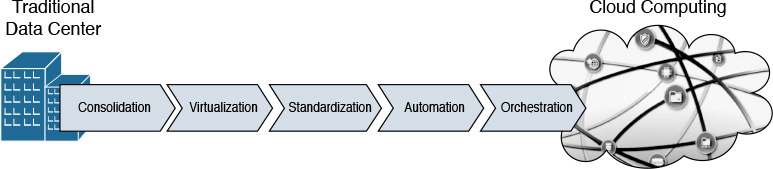
In this “journey to the cloud,” each phase benefits from the results achieved in the previous phase, as you will learn in the following sections. Obviously, depending on the internal characteristics of its data center and the strategic importance of the cloud computing project, each organization can decide the pace at which each phase is carried out. For example, the whole journey can be further accelerated in a cloud deployment that is intentionally isolated in a few racks in a data center to avoid conflicts with traditional data center processes (such as maintenance windows and freezing periods).
Notwithstanding, if the principles ingrained in each of the phases depicted in Figure 4-13 (and described in the following sections) are not fully comprehended, the cloud project may easily run into challenges such as
![]() Cloud services that are not adequate for the cloud consumer objectives
Cloud services that are not adequate for the cloud consumer objectives
![]() Inappropriate time to provision
Inappropriate time to provision
![]() Cloud deployment delays (or even abandonment) due to unforeseen complexity
Cloud deployment delays (or even abandonment) due to unforeseen complexity
![]() Low adoption by end users
Low adoption by end users
Consolidation
A very popular trend in the early 2000s, consolidation aims to break the silos that traditionally exist in a data center infrastructure. In essence, this trend was a direct reaction to a period in data center planning I jokingly call “accidental architecture,” where infrastructure resources were deployed as a side effect of application demand and without much attention to preexisting infrastructure in the facility. For this reason, many consolidation projects were rightfully dubbed rationalization initiatives.
Figure 4-14 portrays a data center consolidation initiative.
The left side of Figure 4-14 depicts three infrastructure silos created with the dedication of resources for each application deployment (A, B, and C). Although this arrangement certainly guarantees security and isolation among application environments, it makes it very difficult for data center administrators to
![]() Allow cross-application connectivity for clients, servers, and storage
Allow cross-application connectivity for clients, servers, and storage
![]() Optimize server and storage utilization, because one application could saturate its infrastructure resources while others remain underutilized
Optimize server and storage utilization, because one application could saturate its infrastructure resources while others remain underutilized

A consolidation strategy such as the one depicted on the right side of Figure 4-14 enables an IT department to achieve various benefits in each technology area. For example:
![]() Networks: Consolidation of networks streamlines connectivity among application users and servers, facilitating future upgrade planning. As a result, the large majority of data centers maintain different network structures per traffic characteristic (such as production, backup, and management) rather than per application.
Networks: Consolidation of networks streamlines connectivity among application users and servers, facilitating future upgrade planning. As a result, the large majority of data centers maintain different network structures per traffic characteristic (such as production, backup, and management) rather than per application.
![]() Storage: Fewer storage devices can hold data for multiple applications, permitting better resource utilization and finer capacity planning.
Storage: Fewer storage devices can hold data for multiple applications, permitting better resource utilization and finer capacity planning.
![]() Servers: The hosting of multiple applications on a single server is afflicted with compatibility issues between hardware and software modules. And although highly standardized environments may achieve consolidation more quickly, they certainly do not represent the majority of scenarios in a traditional data center.
Servers: The hosting of multiple applications on a single server is afflicted with compatibility issues between hardware and software modules. And although highly standardized environments may achieve consolidation more quickly, they certainly do not represent the majority of scenarios in a traditional data center.
Aiming at a greater scope of resource optimization, many IT departments extend their consolidation initiatives toward a reduction of data center facilities and the recentralization of servers provisioned outside of a data center site. In both cases, consolidation helps to decrease management complexity and the number of extremely repetitive operational tasks.
Regardless of how or where it is applied, resource consolidation facilitates the interaction between the cloud orchestrator and the infrastructure, establishing an important basis for the resource pooling essential characteristic of cloud environments.
Virtualization
As discussed in Chapter 2, virtualization techniques generally allow the provisioning of logical resources that offer considerable benefits when compared with their physical counterparts.
Interestingly enough, many virtualization techniques are still extensively deployed to support consolidation processes within data centers. For example:
![]() Virtual local-area network (VLAN): Technique that isolates Ethernet traffic within a shared network structure, providing segmentation for hosts that should not directly communicate with each other.
Virtual local-area network (VLAN): Technique that isolates Ethernet traffic within a shared network structure, providing segmentation for hosts that should not directly communicate with each other.
![]() Storage volume: Allows storage capacity provisioning for a single application server inside of a high-capacity storage system.
Storage volume: Allows storage capacity provisioning for a single application server inside of a high-capacity storage system.
![]() Server virtualization: Permits the provisioning of multiple logical servers inside of a single physical machine.
Server virtualization: Permits the provisioning of multiple logical servers inside of a single physical machine.
Chapter 2 also explained a simple classification system that separates virtualization techniques into three types: partitioning, pooling, and abstraction. From an architectural standpoint, partitioning virtualization techniques enable even higher asset utilization through more sophisticated resource control techniques. In addition, these virtual resources can be combined into virtual data centers (vDCs), which are potential infrastructure templates for future cloud applications or tenants.
Pooling virtualization techniques also support consolidation projects through a greater reduction of management points and proper construction of resource pools. Among the examples of pooling technologies, I can highlight disk array virtualization (which allowed multiple storage devices to be managed as a single unit) and server clusters (which enabled multiple servers to deploy the same application for performance and high-availability purposes).
Abstraction virtualization technologies also help consolidation as they can change the nature of a physical device to a form that may be more familiar to a data center infrastructure team. As an illustration, a virtual switch connecting virtual machines potentially can be managed using the same operational procedures used on a physical switch.
Invariably, all virtualization technologies provide a strong basis for cloud computing deployments through their added flexibility. Because virtual resources can be quickly provisioned without manual operations, it enormously amplifies the creation of offers in the cloud portal and simplifies the job of the cloud orchestrator.
Note
You will have the opportunity to explore virtualization techniques and technologies in much greater depth in subsequent chapters, including, for example, virtual machines (Chapter 5), virtual switches (Chapter 6, “Infrastructure Virtualization”), virtual networking services (Chapter 7), RAID, volumes (Chapter 8, “Block Storage Technologies”), virtual device contexts, virtual PortChannels, fabric extenders, Overlay Transport Virtualization, server I/O consolidation (Chapter 10, “Network Architectures for the Data Center: Unified Fabric”), and service profiles (Chapter 12, “Unified Computing”).
Standardization
Although many organizations feel comfortable lingering in the virtualization phase, they are usually aware that more effort is required to complete the journey toward cloud computing. This awareness typically matures gradually as virtualization technologies naturally lead to overprovisioning and loss of control over the deployed (virtual) resources.
To properly assess the problem, try to picture the amount of development a cloud software stack solution would require if an organization tried to replicate the wild variations of “in the heat of the moment” provisioned infrastructure. In any complex project, excessive variation counteracts replicability, predictability, scalability, and accountability. Henry Ford, a leader in 20th-century mass production, was very cognizant of that fact, as he succinctly stated to the customers of his automobile company: “You can have any color you like, as long as it is black.”
As a logical conclusion, to achieve replicability, predictability, scalability, and accountability—the essential characteristics of a well-oiled machine, be it a car or a cloud—production resources must be standardized. Customization means complexity. Therefore, offering more custom options in a self-service cloud portal catalog means more workflows in the cloud orchestrators, more metering plans, and more effort spent overseeing the cloud infrastructure.
Besides simplifying the service offerings in a cloud, infrastructure standardization can also help to reduce development in the cloud software stack. Such an initiative can happen in multiple dimensions, such as
![]() Uniformity of infrastructure vendor, models, and versions concerning storage, server, and network devices, virtualization software, operating systems, and platform software
Uniformity of infrastructure vendor, models, and versions concerning storage, server, and network devices, virtualization software, operating systems, and platform software
![]() Clear predefinition of resources (physical or virtual) to support user demands
Clear predefinition of resources (physical or virtual) to support user demands
![]() Normalization of provisioning methods and configuration procedures
Normalization of provisioning methods and configuration procedures
Undoubtedly, even without a proper cloud deployment, these different standardization endeavors will certainly drive a data center toward more effective control over deployed resources and troubleshooting processes.
Note
Special attention to standardization process in data centers is given in Chapter 14, “Integrated Infrastructures,” where the concept of pool of devices (POD) is explored in detail.
Automation
Through standardization initiatives in IT, an organization is preparing its operational teams to think massively rather than on a one-off basis. Notwithstanding, even in highly standardized environments, the staggering amount of coordinated infrastructure operations can easily result in human-related mistakes.
Figure 4-15 exemplifies another complex system that is highly susceptible to operational missteps.

To eliminate human error and accelerate execution, sophisticated systems such as an airplane or a data center must rely on the automation of operational procedures. In other words, to automate means to totally excise manual procedures and port standardized procedures into software.
Automation invariably transforms provisioning, migration, and decommissioning processes within a data center. Much as in a modern industrial production line, the operational teams of an automated data center must design tasks that will be carried out by (software) robots and closely monitor their effectiveness, performance, and compliance to service-level agreements (SLAs). In automated environments, maintenance windows are simply ignited through a “great red button” and quickly reversed, if a failure is detected.
Unsurprisingly, data center automation requires approaches that are very usual in software development, where manual tasks are translated into code, which is then tested, debugged, and, finally, put into production.
Note
In highly automated scenarios, policy-driven infrastructure solutions can drastically reduce development effort because they already provide built-in automation, reporting, and analytics functions. You will learn more about such solutions in Chapter 11, “Network Architectures for the Data Center: SDN and ACI,” and Chapter 12.
Orchestration
In the orchestration phase of the journey to the cloud, the cloud software stack benefits from all the hard-earned results from the previous phases:
![]() Reduction of resource silos (consolidation)
Reduction of resource silos (consolidation)
![]() Logical provisioning, resource usage optimization, and management centralization (virtualization)
Logical provisioning, resource usage optimization, and management centralization (virtualization)
![]() Simplicity and predictability (standardization)
Simplicity and predictability (standardization)
![]() Faster provisioning and human error mitigation (automation)
Faster provisioning and human error mitigation (automation)
At this stage, silos between infrastructure and development are already broken. The cloud architect focuses his attention on services that should be offered in the portal catalog according to user requirements. With such defined purpose, the cloud orchestrator is programmed to execute workflows over the automated infrastructure to fulfill the requested services.
A cloud metering plan also must be put in action, with an optional chargeback (or showback) billing strategy aligned to business objectives. Additionally, as explained in Chapter 3, an organization handling the implementation of a cloud may also supplement its service catalog through the secure offering of resources from other clouds through the hybrid cloud deployment model.
Application Programming Interfaces
In the first half of this chapter, you have learned about the most important components in a cloud computing deployment, with special attention given to the functions of the cloud software stack and the evolution of data center infrastructure toward the cloud IT access model.
The efficiency of a cloud implementation depends on how well the cloud software stack components communicate with each other, the cloud infrastructure devices, and even with external clouds. Especially in the case of the cloud orchestrator, a varied spectrum of communication methods facilitates integration within the cloud.
In short, cloud software stack and infrastructure components commonly use the following intercommunication approaches:
![]() Command-line interface (CLI): Developed for user interaction with mainframe terminals in the 1960s. A software component accepts commands via the CLI, processes them, and produces an appropriate output. Although original CLIs depended on serial data connections, modern devices use Telnet or Secure Shell (SSH) sessions over an IP network.
Command-line interface (CLI): Developed for user interaction with mainframe terminals in the 1960s. A software component accepts commands via the CLI, processes them, and produces an appropriate output. Although original CLIs depended on serial data connections, modern devices use Telnet or Secure Shell (SSH) sessions over an IP network.
![]() Software development kit (SDK): Collection of tools, including code, examples, and documentation, that supports the creation of applications for a computer component. With an SDK, a developer can write applications using a programming language such as Java and Python.
Software development kit (SDK): Collection of tools, including code, examples, and documentation, that supports the creation of applications for a computer component. With an SDK, a developer can write applications using a programming language such as Java and Python.
![]() Application programming interface (API): A set of functions, variables, and data structures that enables software components to communicate with each other. Essentially, an API regulates how services from a computer system are exposed to applications in terms of operations, inputs, outputs, and data format.
Application programming interface (API): A set of functions, variables, and data structures that enables software components to communicate with each other. Essentially, an API regulates how services from a computer system are exposed to applications in terms of operations, inputs, outputs, and data format.
Although the origin of APIs is associated with web services (which are basically applications that can communicate through the World Wide Web), they have become a powerful alternative for cloud software integration because they decouple software implementation from its services, freeing developers to use their language of preference in their applications instead of being limited to the specific language used in an SDK.
More importantly, a well-designed API is a key tool for IT automation in general because it can hide the complexity of intricate operations through a simple API request.
For such reasons, cloud software stack developers frequently prefer to employ APIs for module intercommunication. Fitly, infrastructure vendors also have begun to incorporate APIs as a method of configuration, to avoid the difficulties associated with orchestrating these resources through CLIs.
CLI vs API
To illustrate the challenge of using the CLI in this context, imagine that you are developing a cloud orchestrator task that must obtain the firmware version of a network device. With this information in hand, another task in a workflow can decide if this device should be upgraded or not, for example.
Example 4-1 depicts the exact formatting of command output obtained through a CLI session from the orchestrator to the device.
! Cloud orchestrator issues the command
Switch# show version
! And here comes the complete output.
Cisco Nexus Operating System (NX-OS) Software
TAC support: http://www.cisco.com/tac
Copyright (C) 2002-2015, Cisco and/or its affiliates.
All rights reserved.
The copyrights to certain works contained in this software are
owned by other third parties and used and distributed under their own
licenses, such as open source. This software is provided "as is," and unless
otherwise stated, there is no warranty, express or implied, including but not
limited to warranties of merchantability and fitness for a particular purpose.
Certain components of this software are licensed under
the GNU General Public License (GPL) version 2.0 or
GNU General Public License (GPL) version 3.0 or the GNU
Lesser General Public License (LGPL) Version 2.1 or
Lesser General Public License (LGPL) Version 2.0.
A copy of each such license is available at
http://www.opensource.org/licenses/gpl-2.0.php and
http://opensource.org/licenses/gpl-3.0.html and
http://www.opensource.org/licenses/lgpl-2.1.php and
http://www.gnu.org/licenses/old-licenses/library.txt.
Software
BIOS: version 07.17
! In line 23, between columns 17 and 27, lies the actual information the orchestrator needs
NXOS: version 7.0(3)I1(1)
BIOS compile time: 09/10/2014
NXOS image file is: bootflash:///n9000-dk9.7.0.3.I1.1.bin
NXOS compile time: 1/30/2015 16:00:00 [01/31/2015 00:54:25]
Hardware
cisco Nexus9000 C93128TX Chassis
Intel(R) Core(TM) i3-3227U C with 16402548 kB of memory.
Processor Board ID SAL1815Q6HW
Device name: Switch
bootflash: 21693714 kB
Kernel uptime is 0 day(s), 0 hour(s), 16 minute(s), 27 second(s)
Last reset at 392717 usecs after Thu Nov 12 00:13:05 2015
Reason: Reset Requested by CLI command reload
System version: 7.0(3)I1(1)
Service:
plugin
Core Plugin, Ethernet Plugin
Active Packages:
Although you may reasonably disagree, a command-line interface is expressly designed for humans, which justifies how information is organized in Example 4-1. However, an application (such as the cloud orchestrator) would have to obtain the device software version using programming approaches such as
![]() Locating the version string through an exact position (line 23, between columns 17 and 27, in Example 4-1). While this method may offer a striking simplicity, it unfortunately relies on the improbable assumption that all devices and software versions will always position their software version in the same location. For example, any change in the disclaimer text would invalidate your development effort, forcing the development of specific code for each device and software combination.
Locating the version string through an exact position (line 23, between columns 17 and 27, in Example 4-1). While this method may offer a striking simplicity, it unfortunately relies on the improbable assumption that all devices and software versions will always position their software version in the same location. For example, any change in the disclaimer text would invalidate your development effort, forcing the development of specific code for each device and software combination.
![]() Parsing the command output through a keyword such as “NX-OS: version” and capturing the following text. But again, you would have to develop code for all operating systems that are different from NX-OS. On the other hand, parsing the keyword “version” would generate seven different occurrences in Example 4-1, requiring additional development in the application to select the correct string representing the device software version.
Parsing the command output through a keyword such as “NX-OS: version” and capturing the following text. But again, you would have to develop code for all operating systems that are different from NX-OS. On the other hand, parsing the keyword “version” would generate seven different occurrences in Example 4-1, requiring additional development in the application to select the correct string representing the device software version.
While this simple scenario vividly describes some of the obstacles CLIs generate for software developers, Example 4-2 hints at the advantages of using a standard API through the display of the exact result of an API request issued toward the same device.
<?xml version="1.0"?>
<ins_api>
<type>cli_show</type>
<version>1.0</version>
<sid>eoc</sid>
<outputs>
<output>
<body>
<header_str>Cisco Nexus Operating System (NX-OS) Software
TAC support: http://www.cisco.com/tac
Copyright (C) 2002-2015, Cisco and/or its affiliates.
All rights reserved.
The copyrights to certain works contained in this software are
owned by other third parties and used and distributed under their own
licenses, such as open source. This software is provided "as is," and unless
otherwise stated, there is no warranty, express or implied, including but not
limited to warranties of merchantability and fitness for a particular purpose.
Certain components of this software are licensed under
the GNU General Public License (GPL) version 2.0 or
GNU General Public License (GPL) version 3.0 or the GNU
Lesser General Public License (LGPL) Version 2.1 or
Lesser General Public License (LGPL) Version 2.0.
A copy of each such license is available at
http://www.opensource.org/licenses/gpl-2.0.php and
http://opensource.org/licenses/gpl-3.0.html and
http://www.opensource.org/licenses/lgpl-2.1.php and
http://www.gnu.org/licenses/old-licenses/library.txt.
</header_str>
<bios_ver_str>07.17</bios_ver_str>
<kickstart_ver_str>7.0(3)I1(1)</kickstart_ver_str>
<bios_cmpl_time>09/10/2014</bios_cmpl_time>
<kick_file_name>bootflash:///n9000-dk9.7.0.3.I1.1.bin</kick_file_name>
<kick_cmpl_time> 1/30/2015 16:00:00</kick_cmpl_time>
<kick_tmstmp>01/31/2015 00:54:25</kick_tmstmp>
<chassis_id>Nexus9000 C93128TX Chassis</chassis_id>
<cpu_name>Intel(R) Core(TM) i3-3227U C</cpu_name>
<memory>16402548</memory>
<mem_type>kB</mem_type>
<proc_board_id>SAL1815Q6HW</proc_board_id>
<host_name>dcloud-n9k</host_name>
<bootflash_size>21693714</bootflash_size>
<kern_uptm_days>0</kern_uptm_days>
<kern_uptm_hrs>0</kern_uptm_hrs>
<kern_uptm_mins>44</kern_uptm_mins>
<kern_uptm_secs>36</kern_uptm_secs>
<rr_usecs>392717</rr_usecs>
<rr_ctime> Thu Nov 12 00:13:05 2015
</rr_ctime>
<rr_reason>Reset Requested by CLI command reload</rr_reason>
! Here is the information the orchestrator needs
<rr_sys_ver>7.0(3)I1(1)</rr_sys_ver>
<rr_service/>
<manufacturer>Cisco Systems, Inc.</manufacturer>
</body>
<input>show version</input>
<msg>Success</msg>
<code>200</code>
</output>
</outputs>
</ins_api>
Example 4-2 exhibits output from an API (called Cisco NX-API) in a format called Extensible Markup Language (XML). In summary, XML is a flexible text format created by the World Wide Web Consortium (W3C) to represent data exchanged between two or more entities on the Internet.
As you can see in Example 4-2, XML uses start tags (such as <rr_sys_ver>) and end tags (such as </rr_sys_ver>) to express information such as 7.0(3)I1(1) to a program. With previous knowledge about the API, a software developer can easily code an API request to accurately obtain the firmware version using both the start tag and end tag as keywords. Thus, with such information, an application can easily assign the discovered data (firmware version) to a value to an alphanumerical variable, greatly facilitating logic operations. Additionally, this program can be extended to all devices that support the same API.
An alternative data format to XML that is also used in APIs is called JavaScript Object Notation, or simply JSON, which was originally created to transmit data in the JavaScript programming language. As an illustration, Example 4-3 depicts an excerpt of the same API call in JSON.
Example 4-3 Same Output in JSON
{
"ins_api": {
"type": "cli_show",
"version": "1.0",
"sid": "eoc",
"outputs": {
"output": {
"input": "show version",
"msg": "Success",
"code": "200",
"body": {
"header_str": "Cisco Nexus Operating System (NX-OS) Software
TAC supp
[output suppressed]
and
http://www.gnu.org/licenses/old-licenses/library.txt.
",
"bios_ver_str": "07.17",
"kickstart_ver_str": "7.0(3)I1(1)",
"bios_cmpl_time": "09/10/2014",
"kick_file_name": "bootflash:///n9000-dk9.7.0.3.I1.1.bin",
"kick_cmpl_time": " 1/30/2015 16:00:00",
"kick_tmstmp": "01/31/2015 00:54:25",
"chassis_id": "Nexus9000 C93128TX Chassis",
"cpu_name": "Intel(R) Core(TM) i3-3227U C",
"memory": 16402548,
"mem_type": "kB",
"proc_board_id": "SAL1815Q6HW",
"host_name": "dcloud-n9k",
"bootflash_size": 21693714,
"kern_uptm_days": 0,
"kern_uptm_hrs": 0,
"kern_uptm_mins": 21,
"kern_uptm_secs": 51,
"rr_usecs": 392717,
"rr_ctime": " Thu Nov 12 00:13:05 2015
",
"rr_reason": "Reset Requested by CLI command reload",
! And here is the data you need
"rr_sys_ver": "7.0(3)I1(1)",
"rr_service": "",
"manufacturer": "Cisco Systems, Inc."
}
}
}
}
}
As shown in Example 4-3, JSON is also a fairly human-readable data-interchange format that, contrary to its name, is independent from any programming language (just like XML).
In summary, each JSON object
![]() Begins with a left brace, {, and ends with a right brace, }
Begins with a left brace, {, and ends with a right brace, }
![]() Contains an unordered set of name-value pairs separated by commas
Contains an unordered set of name-value pairs separated by commas
![]() Defines data through name-values pairs separated by a colon and a space
Defines data through name-values pairs separated by a colon and a space
Alternatively, a JSON array represents an ordered collection of values, also separated by commas. An array begins with a left bracket, [, and ends with a right bracket, ].
Compared to XML, JSON has less overhead and is arguably simpler and cleaner, which can be useful during code troubleshooting. However, XML is considered more flexible because it allows the representation of other types of data besides text and numbers, including images and graphs. Regardless of this comparison, the large majority of APIs support both formats.
RESTful APIs
In addition to supporting more than one data representation format, the design of an API incorporates the definition of transport protocols, behavior rules, and signaling data. Although a wide variety of such architectures exists, the most commonly used in cloud computing at the time of this writing belong to an architectural style known as Representational State Transfer (REST).
This architectural style was originally proposed by Roy Thomas Fielding in his 2000 doctoral dissertation, “Architectural Styles and the Design of Network-based Software Architectures.” The main purpose of the framework is to establish a simple, reliable, and scalable software communication approach that can adequately support the booming number of web services available on the Internet.
While other API architectures may share similar objectives, all RESTful APIs must adhere to the formal constraints described in Table 4-3 (as defined by Fielding).

RESTful APIs typically use Hypertext Transfer Protocol (HTTP) as a communication standard between applications. With Roy Fielding also being one of its main creators, HTTP can be considered one of the fundamental pillars of the Web, embodying the main method for the communication between web browsers and servers.
RESTful APIs can also use HTTPS (HTTP Secure) to enforce security measures, such as encryption and authentication.
Figure 4-16 illustrates a simple HTTP transaction between two applications, as defined in Request for Comments (RFC) 2068, from the Internet Engineering Task Force (IETF).

As Figure 4-16 shows, a client first initiates an HTTP transaction establishing a TCP connection (using destination port 80, by default) with the server, using a three-way handshake composed of TCP SYN, TCP SYN/ACK, and TCP ACK messages. Within one or more connections, a client sends a request to the server containing the parameters described in Table 4-4.

After the server correctly receives the client request (as the TCP ACK signals), it issues an HTTP response with the parameters described in Table 4-5.

A RESTful API uses an HTTP request method to represent the action according to its intent. The most used actions are
![]() GET: Used to read information from the server application. This action usually expects a code 200 (OK) and appended data that corresponds to the request.
GET: Used to read information from the server application. This action usually expects a code 200 (OK) and appended data that corresponds to the request.
![]() POST: Creates objects within the server application. It usually expects a code 201 (Created) and a new resource identifier.
POST: Creates objects within the server application. It usually expects a code 201 (Created) and a new resource identifier.
![]() PUT: Updates a preexisting object in a server application. It commonly expects a code 200 (OK).
PUT: Updates a preexisting object in a server application. It commonly expects a code 200 (OK).
![]() DELETE: Deletes resource and expects code 200 (OK) under normal conditions.
DELETE: Deletes resource and expects code 200 (OK) under normal conditions.
As an illustration, Figure 4-17 portrays an example of an API request executed through POSTMAN, an application that exposes all information contained in such operations, helping the development, testing, and documentation of an API.

Note in Figure 4-17 that the API request will be performed through a POST action, signaling that a show version command will be issued to the network device whose management IP address is 198.18.133.100. Additionally, the request will be applied to a URL defined as http://198.18.133.100/ins with a body containing information about the API version (“1.0”), type of input (“cli_show”), input command (“show version”), and output format (“json”).
Figure 4-18 displays the response received after clicking Send.

In Figure 4-18, the network device response has a code 200, signaling that no error has occurred. And included in the “body” name, you can observe an excerpt from the same output from Example 4-3.
The cloud components discussed earlier in the chapter in the section “Cloud Computing Architecture” frequently use RESTful APIs in multiple ways, such as
![]() In the communication between cloud orchestrator and infrastructure components
In the communication between cloud orchestrator and infrastructure components
![]() In the integration between cloud software stack components (portal requests workflow execution on cloud orchestration, for example)
In the integration between cloud software stack components (portal requests workflow execution on cloud orchestration, for example)
![]() In requests to the cloud portal from user applications (not end users) that are requesting cloud resources
In requests to the cloud portal from user applications (not end users) that are requesting cloud resources
There are many other API formats, such as Windows PowerShell and Remote Procedure Call, whose description is out of the scope of this chapter. But regardless of their origin, all APIs should aim for clarity, simplicity, completeness, and ease of use. Above all, an API designer must remember that, much like diamonds, APIs are forever (as soon as they are published and used in development code).
Around the Corner: OpenStack
Originally created by the U.S. National Aeronautics and Space Administration (NASA) and Rackspace in 2010, OpenStack is a community development initiative to develop open source software to build public and private scalable clouds. In essence, it is a cloud software stack that can control infrastructure resources in a data center through a web-based dashboard or via the OpenStack API.
An OpenStack implementation consists of the deployment of multiple services, which are developed in individual development projects. Table 4-6 describes some of the most popular OpenStack services, as they are known at the time of this writing.

All of the services described in Table 4-6 interact through predefined APIs. Additionally, these software modules can integrate with infrastructure elements, such as servers, network devices, and storage systems, through plug-ins, which essentially normalize the backend operations of each service to these devices. Third-party vendors can integrate their products through drivers that translate the functions of a plug-in to a specific device model.
OpenStack is maturing at an incredible rate, including new features and even projects through new versions being released every six months at each OpenStack summit. The OpenStack version naming convention follows alphabetical order, such as Austin, Bexar, Cactus, Diablo, Essex, Folsom, Grizzly, Havana, Icehouse, Juno, Kilo, and Liberty.
Further Reading
![]() OpenStack: https://www.openstack.org/
OpenStack: https://www.openstack.org/
![]() OpenStack at Cisco: http://www.cisco.com/go/openstack
OpenStack at Cisco: http://www.cisco.com/go/openstack
Exam Preparation Tasks
Review All the Key Topics
Review the most important topics in this chapter, denoted with a Key Topic icon in the outer margin of the page. Table 4-7 lists a reference of these key topics and the page number on which each is found.

Table 4-7 Key Topics for Chapter 4
Complete the Tables and Lists from Memory
Print a copy of Appendix B, “Memory Tables” (found on the CD), or at least the section for this chapter, and complete the tables and lists from memory. Appendix C, “Answers to Memory Tables,” also on the CD, includes completed tables and lists so that you can check your work.
Define Key Terms
Define the following key terms from this chapter, and check your answers in the glossary:
application programming interface (API)
Extensible Markup Language (XML)