
Chapter 11. Network Architectures for the Data Center: SDN and ACI
This chapter covers the following topics:
![]() Cloud Computing and Traditional Data Center Networks
Cloud Computing and Traditional Data Center Networks
![]() The Opposite of Software-Defined Networking
The Opposite of Software-Defined Networking
![]() Application Centric Infrastructure
Application Centric Infrastructure
This chapter covers the following exam objectives:
![]() 4.1 Describe network architectures for the data center
4.1 Describe network architectures for the data center
![]() 4.1.b SDN
4.1.b SDN
![]() 4.1.b.1 Separation of control and data
4.1.b.1 Separation of control and data
![]() 4.1.b.2 Programmability
4.1.b.2 Programmability
![]() 4.1.b.3 Basic understanding of OpenDaylight
4.1.b.3 Basic understanding of OpenDaylight
![]() 4.1.c ACI
4.1.c ACI
![]() 4.1.c.1 Describe how ACI solves the problem not addressed by SDN
4.1.c.1 Describe how ACI solves the problem not addressed by SDN
![]() 4.1.c.3 Describe the role of the APIC Controller
4.1.c.3 Describe the role of the APIC Controller
In Chapter 10, “Network Architectures for the Data Center: Unified Fabric,” you learned about a series of technological innovations that Cisco amalgamated into a highly successful data center network architecture: Cisco Unified Fabric. Although such architecture has become a primary driver for the evolution of numerous data centers worldwide, it is essentially based on concepts and abstractions that were conceived during the 1970s and 1980s, as the Internet was being formed.
During the last half of the 2000s, inspired by the noticeable differences between networking and other computer systems, a group of researchers began to question whether established networking practices were actually appropriate for the future of IT. Through creativity and healthy naïveté, these researchers proposed many breakthrough new approaches to disrupt well-known network designs and best practices. These new approaches have been collectively given the umbrella term Software-Defined Networking (SDN).
As the world-leading networking manufacturer, Cisco has actively participated in developing the large majority of these cutting-edge approaches, while also creating many others. Combining innovation and intimate knowledge about customer demands, Cisco conceived a revolutionary data center network architecture called Cisco Application Centric Infrastructure (ACI). Specially designed for data centers involved in cloud computing and IT automation, ACI addresses many challenges that were overlooked by earlier SDN approaches.
As mentioned in Chapter 10, the CLDFND exam requires knowledge about two other Cisco data center networking architectures besides Cisco Unified Fabric: Software-Defined Networking and Cisco Application Centric Infrastructure. This chapter focuses on both, exploring the dramatic paradigm shifts they have caused in data center infrastructure and cloud computing projects.
“Do I Know This Already?” Quiz
The “Do I Know This Already?” quiz allows you to assess whether you should read this entire chapter thoroughly or jump to the “Exam Preparation Tasks” section. If you are in doubt about your answers to these questions or your own assessment of your knowledge of the topics, read the entire chapter. Table 11-1 lists the major headings in this chapter and their corresponding “Do I Know This Already?” quiz questions. You can find the answers in Appendix A, “Answers to Pre-Assessments and Quizzes.”

1. Which of the following is not a challenge data center networks bring to cloud computing?
a. Scalability
b. Provisioning model
c. Resource decommission
d. VLAN ID depletion for tenant isolation
e. I/O consolidation
2. Which of the following options is not directly related to SDN?
a. “Clean Slate” program
b. OpenStack
c. Network programmability
d. Provisioning agility
3. Which of the following is not a generic network controller objective?
a. Exclusively deploy the control plane of a network
b. Network abstraction for simpler provisioning
c. Aggregation of device information
d. Single point of access for provisioning
4. Which of the following correctly define the network planes? (Choose all that apply.)
a. The data plane corresponds to all processes related to the transport of data packets in a network device.
b. The control plane makes the decisions that the data plane carries out.
c. The data plane makes the decisions that the control plane carries out.
d. The control plane takes care of all communications between network devices in traditional networks.
e. The control plane is represented through software running on general-purpose CPUs, while the data plane is executed on specialized ASICs.
5. Which of the following is not a valid action for an OpenFlow network device?
a. Send to SDN controller
b. Send to egress interface
c. Send to all ports except ingress
d. Check TCP flags
e. Send to input port
6. Which of the following is the main function of SAL in OpenDaylight?
a. Provide abstraction for southbound protocols
b. Directly configure OpenFlow compatible devices
c. Handle REST API calls
d. Clustering
e. GUI
7. Which of the following is not an ACI component?
a. Nexus 9000
b. APIC
c. AVS
d. Nexus 1000V
e. Partner ecosystem
8. Which of the following contains constructs that are not part of the ACI policy model?
a. Context, tenant, subnet
b. Broadcast domain, context, connectivity profile
c. Contract, filter, subject
d. Service chain, contract, EPG
9. Which of the following is not a function of APIC?
a. Control plane
b. Policy
c. GUI
d. Fabric management
e. API
10. Which of the following are benefits from Cisco Application Centric Infrastructure? (Choose all that apply)
a. Distributed default gateway
b. VM provisioning
c. Encapsulation normalization
d. Multi-hypervisor integration
e. Separation of control and data planes
Foundation Topics
Cloud Computing and Traditional Data Center Networks
Because cloud computing is an IT service delivery model, cloud implementations become more flexible as more infrastructure elements are orchestrated to support requests from a cloud end user. And as the main system responsible for transporting data to users and between cloud resources, the data center network should be included prominently in this integration.
However, some principles that supported the evolution of networking during the past 40 years are incompatible with the expectations surrounding cloud computing. In Chapter 10, you learned about techniques and designs created to satisfy the demands related to server virtualization escalation in data centers. For example, data center fabrics can definitely help cloud computing projects through the consolidation of Layer 2 silos that are still very common in classical three-tier topologies. And as a direct consequence, a fabric can more easily become a single pool of networking resources for a cloud software stack. Yet, the large majority of data center networks (and fabrics) are still provisioned through practically artisanal procedures. As an illustration, Figure 11-1 depicts a network configuration procedure that is probably happening somewhere as you read these words.
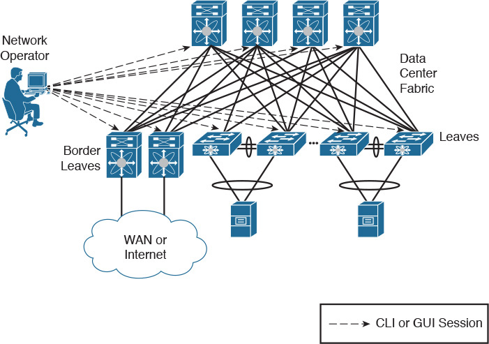
In the figure, a network engineer must provision the network to receive a new application consisting of virtual machines that can potentially be connected to any leaf port on this generic fabric. After some time translating the application requirements into networking terms, the professional performs the following operations:
Step 1. Creates three VLANs in every switch.
Step 2. Adds these VLANs to every leaf access port.
Step 3. Configures a default gateway for each VLAN at some point of this network (border leaves in the case of Figure 11-1).
Because most network engineers still use command-line interface (CLI) sessions or a device graphical user interface (GUI) to fulfill these steps, their resulting configurations are generally considered very error-prone and difficult to troubleshoot. And although some corporations maintain detailed documentation about past and current network configurations, this practice is hardly the norm for the majority of data center networks.
This simple example should already reveal to you the great chasm that exists between resource provisioning for networks and resource provisioning for other technologies such as server virtualization. To make matters worse, I’m personally aware of many companies in which VLANs can be added (or removed) only during monthly maintenance windows, invariably making the network team the biggest contributor to application deployment delays.
As you can easily deduce, such manual operations are highly unsuitable for cloud computing environments. For this reason alone, I completely understand why some cloud architects plan to pre-configure all 4094 available VLANs every port of a network, avoiding additional procedures during the provisioning of cloud resources. However, leveraging this design decision, these architects are disregarding important aspects such as
![]() Flooding and broadcast traffic may severely impact all ports, inadvertently affecting other cloud tenants.
Flooding and broadcast traffic may severely impact all ports, inadvertently affecting other cloud tenants.
![]() VLANs are not the only network consumable resource. Other configurations such as access-control lists (ACLs), firewall rules, and server load balancer services will still need provisioning as new tenants sign up for cloud services.
VLANs are not the only network consumable resource. Other configurations such as access-control lists (ACLs), firewall rules, and server load balancer services will still need provisioning as new tenants sign up for cloud services.
Whereas cloud computing environments may be prepared to welcome new tenants, they should also expect that any of them may discontinue cloud services at any time. And because the network resources for a tenant are essentially defined as a set of configuration lines spread over multiple devices, decommissioning is considered an almost insurmountable obstacle in traditional networks. Consequently, even after tenants or applications are discontinued, their corresponding VLANs, routes, ACL entries, and firewall rules continue to clutter troubleshooting procedures forever.
With the popularization of cloud computing projects, and the increasing demand for automation and standardization in data centers, networks began to be seriously reexamined within academic studies, service provider meetings, and boardrooms in light of the new SDN technologies.
The Opposite of Software-Defined Networking
The formal beginning of many SDN initiatives happened in 2006 with Stanford University’s Clean Slate Program, a collaborative research program intended to design the Internet as if it were being created anew while leveraging three decades of hindsight.
As clearly stated in its mission, Clean Slate did not outline a precise approach, a decision that enabled program participants to pursue extremely creative small projects and very interesting endeavors. And even after its deactivation in 2012, the project’s legacy is apparent today in the numerous network solutions being offered to support automation and cloud computing deployments in enterprise corporations and service providers.
Unsurprisingly, presenting a conclusive definition for SDN is quite difficult. This difficulty is compounded by the SDN marketing bandwagon. With huge interest in SDN turning into hype in the early 2010s, many vendors tried to associate SDN as closely as possible with their own approach. As an example, the following list paraphrases some definitions of SDN I have compiled after a quick web search:
![]() “SDN is an approach to computer networking where IT administrators can manage networks through the abstraction of lower-level functionalities.”
“SDN is an approach to computer networking where IT administrators can manage networks through the abstraction of lower-level functionalities.”
![]() “SDN is an emerging architecture that can be translated into speed, manageability, cost reduction, and flexibility.”
“SDN is an emerging architecture that can be translated into speed, manageability, cost reduction, and flexibility.”
![]() “SDN enables network control to become directly programmable as the underlying infrastructure is abstracted for applications and network services.”
“SDN enables network control to become directly programmable as the underlying infrastructure is abstracted for applications and network services.”
![]() “SDN is the virtualization of network services in order to create a pool of data transport capacity, which can be flexibly provisioned and reutilized according to demand.”
“SDN is the virtualization of network services in order to create a pool of data transport capacity, which can be flexibly provisioned and reutilized according to demand.”
As you can see from this small sampling, such definitions of SDN wildly vary from precise descriptions of specific technologies to very vague statements. In my humble opinion, the effort to propose a definitive conceptualization of SDN is futile simply because these new approaches are intended to break current paradigms and, consequently, are only bounded by creativity.
Because this chapter will explore SDN approaches that will contradict the statements made previously, allow me to introduce a definition for SDN in a different manner.
According to John Cleese (genius from legendary comedy troupe Monty Python and neuropsychological studies enthusiast), nobody really knows how creativity actually happens, but it is pretty clear how it does not. Furthermore, as Cleese jokes in his famous lectures about creativity and the human mind, a sculptor explained his method of creating beautiful elephant statues: simply remove from the stone what is not an elephant.
In a similar vein, allow me to propose the following question: what is the opposite of SDN for you? Please give yourself some time for reflection before reading the next paragraph.
If you believe hardware-defined networking (HDN) is the correct answer, you are not alone. Respectfully, I do not agree with that answer, for what I think are some compelling reasons. Since the inception of the ARPANET in the late 1960s, networks have been based on devices composed of both hardware and software (network operating system), the latter of which is as carefully designed and developed as other complex applications such as enterprise resource planning (ERP). In its current model, neither hardware nor software defines how a network behaves, but rather a higher layer of control called Homo sapiens defines its behavior. Because this “layer” is directly involved in every single change on most networks, I believe human-defined networking genuinely represents what is not SDN. (But if you still prefer hardware-defined networking, at least we can agree on the same acronym.)
As a result, SDN can be defined as the set of technologies and architectures that allow network provisioning without any dependence on human-based operations. In truth, such conclusion may explain why the large majority of SDN approaches (including OpenFlow and Cisco ACI, which will be discussed in a later section) pursue the concept of the network as a programmable resource rather than a configurable one. And as many network professionals can attest, manual configurations can easily become an operational headache as more changes are required or the network scales.
The ways in which programming can help remove these repetitive menial tasks will be further explored in the next section.
Network Programmability
Figure 11-1 earlier in the chapter portrays all the characteristics of a configurable network. In this type of network, a design is essentially an abstraction shared by a set of human brains and, with some luck, expressed in some kind of documentation. As I have explained, network engineers employ CLI sessions (using Telnet or SSH protocols) or a device GUI to manually issue commands on each network device (including switches, routers, firewalls, and so forth).
Network Management Systems
Although some network professionals still insist on using text files containing multiple lines of commands pasted into a CLI (you are only allowed to laugh about this ingenious technique if you have never used it), many others employ a network management system (NMS) to speed up the network configuration process. As Figure 11-2 demonstrates, these systems scale the range of each single configuration change, extending it to a larger group of network devices, from a provisioning standpoint.

An NMS can be considered a variation of manual configurations because human interaction is still required on the majority of operations. After receiving an order from an operator, an NMS usually issues a batch of CLI commands or Simple Network Management Protocol (SNMP) requests to multiple devices in a network or fabric.
Generally speaking, an NMS still requires from its operators a deeper knowledge about managed devices and their role within the network topology. For this reason, these management systems are usually challenging to operate in multi-vendor networks.
Tip
Cisco Data Center Network Manager (DCNM) is the most common choice of NMS for Nexus-based networks. You can find more details about this solution in Chapter 13, “Cisco Cloud Infrastructure Portfolio.”
Automated Networks
Notwithstanding, the evolution of NMSs carried the seeds for the next step in network provisioning. Through wizards and tools, these systems introduced automation to many network teams. In essence, this concept is defined as the ability of a network to deploy complex configurations through predefined tasks without the need of human intervention.
Automated networks commonly require the use of orchestration software (orchestrators) and the creation of workflows containing multiple standardized procedures that need to be executed in order. These orchestrators usually provide graphical tools and out-of-the-box tasks that enable network engineers to build custom workflows based on best practices and specific company requirements.
As an example, Figure 11-3 exhibits how an orchestrator can automate the creation of the same resources described in Figures 11-1 and 11-2.

In Figure 11-3, before any effective configuration, the network engineer builds (or imports) workflows on the orchestrator using the same three network operations depicted in Figure 11-2 (create VLANs, add VLAN to all access ports, and create default gateways). With this scenario, this workflow can be summoned through a single action (“Tenant Network” in this example). Additionally, to avoid cumulative errors and incomplete configurations, workflows have the capability to reverse all previously executed configurations in the case of an error in the execution of any task.
Much like NMSs, most network orchestrators usually require previous information such as IP address, hardware model, and software version before executing any workflow. But rather than executing each procedure manually, network engineers can focus on building efficient workflows and monitoring their execution in such networks. As mentioned in Chapter 4, “Behind the Curtain,” this arrangement typically is adopted in cloud computing environments via cloud orchestrators that can coordinate devices from multiple infrastructure areas, including server, storage, and (of course) networking.
Although its name may not advertise its cloud credentials, Cisco Unified Computing System (UCS) Director is one of the most complete cloud orchestrators available at the time of this writing. In addition to containing numerous predefined tasks for Cisco data center solutions, UCS Director provides out-of-the-box support for third-party devices and a graphical tool for workflow composing.
Even with the gradually increasing adoption of network automation, the flexibility automated networks achieve still pales when compared with fully programmable resources, such as servers and microcomputers. To better explain this gap, let’s take a brief digression into the subject of software development.
Programmable Networks
A computer program (or application) can be defined as a sequence of instructions written to perform a specific task on a computer system. A software developer uses keywords and the syntax of a programming language to develop a source code. When executed, the code consumes computing resources to fulfill the original objective of the program.
Computer programmers increase the usefulness of their programs by making them compatible with a wide array of hardware platforms and operating systems. Suitably, programming languages are usually not concerned with the specific characteristics of a computer system. Instead, their functions are abstracted enough to allow a compiler or interpreter to translate them into machine language, which includes a CPU basic instruction set and memory management.
Hence, what would constitute a programmable network? In similar terms, this network should offer a collection of instructions that allows the development of programs executing specific tasks on a network.
Figure 11-4 explores a simple example of a network application.

In this scenario, a network application was built to deploy a tenant network using the following pseudocode:
Step 1. Span the topology to check which VLANs are already in use.
Step 2. With such information, calculate which three VLANs in the available pool can be used for the next tenant.
Step 3. Configure the VLANs in the network devices.
Step 4. Add the VLANs to all server ports.
Step 5. Locate which device has routing capabilities and configure the default gateway for these VLANs.
Through this simple example, you can already recognize the tremendous potential for network programmability. Because it provides tools for software development, customers can create custom solutions for their specific problems, rather than waiting for vendor roadmaps.
Furthermore, code sharing can greatly reduce the amount of development effort spent on network programming. For example, using resources such as GitHub or other open source communities, developers can leverage existing programs as if they were assembly parts on their projects, and even share the final result with the development community, in a rather virtuous circle of network modernization.
To support the interest in programmable networks, a set of sophisticated tools was added to network devices, including

![]() Application programming interfaces (APIs): As explained in Chapter 4, a well-designed API greatly facilitates the writing of source code for network applications. Roughly speaking, an API offers an easy alternative for applications that would be forced to parse strings containing outputs from a CLI session to gather information required for an algorithm decision.
Application programming interfaces (APIs): As explained in Chapter 4, a well-designed API greatly facilitates the writing of source code for network applications. Roughly speaking, an API offers an easy alternative for applications that would be forced to parse strings containing outputs from a CLI session to gather information required for an algorithm decision.
![]() Embedded programming languages: A network device can facilitate network application execution through a programming language interpreter running on its operating system. With such a feature, reactions can be performed as soon as a network event occurs. As an example, the Nexus 9000 switches possess a Python interpreter, Python being an extremely popular language among infrastructure developers due to its flexibility and easiness to learn.
Embedded programming languages: A network device can facilitate network application execution through a programming language interpreter running on its operating system. With such a feature, reactions can be performed as soon as a network event occurs. As an example, the Nexus 9000 switches possess a Python interpreter, Python being an extremely popular language among infrastructure developers due to its flexibility and easiness to learn.
![]() Access to lower-level software: Most network operating systems depend on application-specific integrated circuit (ASIC) firmware and operating systems such as Linux to coordinate their boot. Consequently, some developers are keenly interested in accessing these lower-level software pieces to achieve specific results, increase visibility over device information, and leverage open source code.
Access to lower-level software: Most network operating systems depend on application-specific integrated circuit (ASIC) firmware and operating systems such as Linux to coordinate their boot. Consequently, some developers are keenly interested in accessing these lower-level software pieces to achieve specific results, increase visibility over device information, and leverage open source code.
![]() Application hosting: Rather than demanding external computers to run network programs, network devices can offer computing resources for application hosting in the form of dedicated hardware modules or space in the their supervisor (running VMs or Linux containers). Moreover, these devices offer a highly strategic position for their hosted applications because they can gather data that may be impossible (or simply too expensive) for external computers to gather.
Application hosting: Rather than demanding external computers to run network programs, network devices can offer computing resources for application hosting in the form of dedicated hardware modules or space in the their supervisor (running VMs or Linux containers). Moreover, these devices offer a highly strategic position for their hosted applications because they can gather data that may be impossible (or simply too expensive) for external computers to gather.
![]() Configuration management software: This category of software includes open source configuration management utilities with a declarative language that describes the target state for an IT resource (a server, storage device, and, as you can guess, a network device). Arguably, the best known examples of configuration management software are Puppet, Chef, and Ansible. Cisco NX-OS supports many of these intent-based automation methods through embedded client software such as Puppet agent and Chef client (Ansible is agentless), which allows provisioning, configuration, and management tasks from their server component (Puppet master, Chef server, or Ansible control nodes, respectively). Besides repetitive and error-prone configuration tasks involving VLANs, QoS, and ACLs, these tools are also used for network device PowerOn Auto Provisioning (POAP), the automated process of upgrading software images and installing configuration files on Cisco Nexus switches that are being deployed in the network for the first time.
Configuration management software: This category of software includes open source configuration management utilities with a declarative language that describes the target state for an IT resource (a server, storage device, and, as you can guess, a network device). Arguably, the best known examples of configuration management software are Puppet, Chef, and Ansible. Cisco NX-OS supports many of these intent-based automation methods through embedded client software such as Puppet agent and Chef client (Ansible is agentless), which allows provisioning, configuration, and management tasks from their server component (Puppet master, Chef server, or Ansible control nodes, respectively). Besides repetitive and error-prone configuration tasks involving VLANs, QoS, and ACLs, these tools are also used for network device PowerOn Auto Provisioning (POAP), the automated process of upgrading software images and installing configuration files on Cisco Nexus switches that are being deployed in the network for the first time.
![]() Extensible Message and Presence Protocol (XMPP): XMPP is open technology that is commonly used for instant messaging and presence. Through an embedded XMPP client, network devices can be easily integrated into an efficient message bus and, therefore, be configured as a group.
Extensible Message and Presence Protocol (XMPP): XMPP is open technology that is commonly used for instant messaging and presence. Through an embedded XMPP client, network devices can be easily integrated into an efficient message bus and, therefore, be configured as a group.
Although these tools can help turn networks into a programmatically consumable resource, their highly variable types of network topology and potential large number of devices bring an immense complexity to network application development. Moreover, devices usually perform different roles inside these topologies (core, aggregation, access, spine, and leaf, for example) and include a broad spectrum of networking services such as firewalls, server load balancers, and network analyzers.
Network controllers were created to facilitate the interaction with distinct topologies and network implementations. Basically, these controllers are responsible for the complete configuration of managed network devices, offering a simpler view of the whole network for application developers.
Figure 11-5 portrays the concept of a network controller in more detail.

Acting as a point of aggregation for all communication with network programs and other applications (which are northbound from the controller), a network controller hides the network complexity from these software pieces. Meanwhile, all “low level” operations are executed through a variety of communication procedures with the controlled network devices (southbound from the controller).
Network controllers are not exactly a brand new concept. Besides being very popular for indoor wireless implementations, these controllers have been used as a central point of arbitration of WAN optimization features that leverage IP service-level agreement (SLA) traffic probes. Also, in an interesting way, one can argue that the Nexus 1000V Virtual Supervisor Module (VSM) also acts as a controller for the Virtual Ethernet Modules (VEMs), as explained in Chapter 6, “Infrastructure Virtualization.”
Note
It is important that you understand the software components I have discussed in this section (NMS, orchestrator, network programs, and controllers) more as functions than products per se. Such advice will be useful for you in the future, as you get to know orchestration solutions that have programmability features, network controllers with automation tools, and so forth.
SDN Approaches
Even through the great tornado of innovation in recent years, it is already possible to observe two SDN approaches that have generated more interest from companies looking for more dynamic data center networks:
![]() Separation of the control and data planes
Separation of the control and data planes
![]() Software-based virtual overlays
Software-based virtual overlays
In the following sections you will learn about their principles, characteristics, and operational details.
Separation of the Control and Data Planes
There are many ways to categorize functions on a network device. One of the most popular methods uses network planes to characterize these processes. Table 11-2 describes the main differences between the data and control planes.

Note
You may encounter several technical books and articles that define an additional plane. In these sources, the management plane reunites all device components that exclusively deal with management operations, such as the CLI, GUI, and SNMP. For the sake of simplicity, I will consider that these elements are part of the control plane in this writing.
One of projects spawned from the Clean Slate program is OpenFlow. Its enthusiasts state that whereas the data plane already possesses a great abstraction model (the famous Open Systems Interconnection [OSI] layers), the control plane does not share the same advantage on traditional network devices. Instead, for each new control plane problem (such as route exchange and topology discovery), an additional process is stacked into the network operating system, with low modularity and development efficiency.
Because these processes are part of a vendor network operating system design, there is very little standardization in how the control plane is built between solutions from different manufacturers. And as I have discussed in the section “Network Programmability,” such disparity greatly challenges the use of networks as programmable resources.
As a counterpart to these difficulties, OpenStack suggests a radically different approach, which is summarized in Figure 11-6.

As represented on the left side of Figure 11-6, traditional network devices incorporate both control and data planes. In an OpenFlow network, shown on the right, an SDN controller is deployed to consolidate all control plane processes. As a consequence, the distributed network devices only execute data plane functions according to received orders from the controller.
By definition, any network controller enjoys a privileged position in a network because it sends and receives information from all controlled devices through a southbound protocol. By concentrating all control plane decisions from a network, an SDN controller can recognize events and patterns detected on the devices and induce reactions that may be simply impossible to replicate in a network composed of distributed control planes.
The OpenFlow Protocol
The lack of control plane processes on the network devices demands a very detailed behavior description from the SDN controller. Such operation is carried out by the southbound protocol eponymously named OpenFlow, which essentially constitutes a low-level method that configures a network device through the manipulation of its internal flow table.
In a nutshell, the flow table represents how the network device hardware forwards an IP packet or an Ethernet frame. For the sake of simplicity, let’s consider the MAC address table on a traditional Ethernet switch as an example of a flow table. Under this prism, the device uses the table to select a forwarding decision according to the destination MAC address on a frame. Figure 11-7 illustrates the most common actions on these devices.
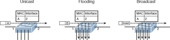
Figure 11-7 shows three situations involving the same Ethernet switch, whose single MAC address table entry signals that all frames with a destination MAC address A should be sent to interface 2. The first situation, on the left, represents unicast forwarding, where the switch sends the frame according to an existing MAC address table entry.
If the switch receives a frame with a MAC address that is not in the table, it forwards the frame to all ports except the one from which it received the frame, in a process called flooding, as shown in the center of Figure 11-7. A similar behavior happens when a broadcast frame arrives at a switch port with an explicit destination address ffff.ffff.ffff, as shown on the right. Under these circumstances, the switch MAC address table defines a single traffic class (frames with destination MAC address A) and performs either of two actions: forwards to an interface or forwards to all other interfaces.
Adversely, the flow table on an OpenFlow device demonstrates much more flexibility when compared with a MAC address table. Besides destination MAC address, OpenFlow allows the use of many other fields from Ethernet, IP, TCP, and UDP headers as conditions for a pre-established action.
In OpenFlow implementations, the SDN controller is solely responsible for flow table entry insertion and deletion for all controlled devices. An as an illustration, Figure 11-8 highlights an SDN controller sending a flow entry to a device via the OpenFlow protocol.

In the figure, the SDN controller populates the flow table of an OpenFlow switch with an entry that defines that all incoming frames from interface 1 that are tagged with VLAN 400 must be forwarded to interface 4. While this entry defines source-based forwarding, OpenFlow allows multiple other combinations to create very specific traffic classes.
Also, the protocol offers a wide range of actions that can be applied to these classes, such as
![]() Forward to all other ports
Forward to all other ports
![]() Encapsulate and forward to the SDN Controller for further analysis
Encapsulate and forward to the SDN Controller for further analysis
![]() Drop
Drop
A famous philosopher named Stan Lee once said: “With great power there must also come—great responsibility.” Whereas flow programming allows almost endless possibilities of traffic forwarding, the SDN controller must consider all required behaviors from an OpenFlow device when it populates flow table entries. For example, if broadcast communications are desired to support ARP requests, the SDN controller must insert a flow entry specifying that frames with MAC address ffff.ffff.ffff must be forwarded to all other ports on all devices. In addition, the controller must introduce flow entries to avoid loops and allow the communication with non-OpenFlow devices. Taking these precautions into account, OpenFlow brings huge value for academic research and for networks that demand an extremely high level of customization.
Unlike other protocols, OpenFlow is standardized by the Open Network Forum (ONF), a nonprofit, user-driven organization dedicated to the adoption and improvement of SDN through open standards. Cisco, among many other networking vendors, is a member of ONF.
Since its formation in 2011, ONF has primarily focused on the development of the OpenFlow protocol, releasing new versions with enhancements such as
![]() Additional flow headers as VLAN Class of Service (CoS) and IP Type of Service (ToS)
Additional flow headers as VLAN Class of Service (CoS) and IP Type of Service (ToS)
![]() Additional OpenFlow device actions such as: redirecting the packet to the device local CPU or forwarding it back to input port.
Additional OpenFlow device actions such as: redirecting the packet to the device local CPU or forwarding it back to input port.
More details about OpenFlow can be found at http://www.opennetworking.org.
OpenDaylight
Although the OpenFlow protocol can unlock great potential for innovation on networks that require granular forwarding policies, this southbound communication standard is only one part of an SDN implementation. As a fairly simple protocol, OpenFlow relinquishes more responsibilities to the SDN controller. Besides, to fulfill one of the original main objectives of the Clean Slate Program, a programmable network architecture must also address topics such as northbound API definitions, controller performance and availability, and the inclusion of other southbound protocols for legacy solutions.
Many networking vendors (including Cisco) and open development communities have effectively addressed these gaps via a joint effort called OpenDaylight (ODL). Founded in 2013 and led by the Linux Foundation, this collaborative project originally aspired to attain the following objectives:
![]() Provide a common architectural framework and a robust array of services to enable a wide breadth of applications and use cases for SDN and network function virtualization (NfV)
Provide a common architectural framework and a robust array of services to enable a wide breadth of applications and use cases for SDN and network function virtualization (NfV)
![]() Offer an open, highly available, modular, extensible, scalable, and multiprotocol controller infrastructure built for SDN deployments on modern multivendor networks
Offer an open, highly available, modular, extensible, scalable, and multiprotocol controller infrastructure built for SDN deployments on modern multivendor networks
![]() Enable a service abstraction platform that allows the development of network applications that can be ported to a wide array of network devices and southbound protocols
Enable a service abstraction platform that allows the development of network applications that can be ported to a wide array of network devices and southbound protocols
Figure 11-9 introduces the original structure of the OpenDaylight architecture.

From top to bottom, the architecture delineates how users and applications can interact with the OpenDaylight controller. Besides supporting a modular RESTful API and a default GUI (OpenDaylight User Experience [DLUX]), the ODL controller also communicates to applications through northbound interfaces such as these:
![]() Virtual Tenant Network (VTN) coordinator: Application that builds virtual networks in ODL controllers
Virtual Tenant Network (VTN) coordinator: Application that builds virtual networks in ODL controllers
![]() OpenStack Neutron: OpenStack networking project (discussed later in more detail in the section “Around the Corner: OpenStack Neutron”)
OpenStack Neutron: OpenStack networking project (discussed later in more detail in the section “Around the Corner: OpenStack Neutron”)
![]() SDN Interface (SDNi): OpenDaylight project that intends to enable inter-ODL controller communication
SDN Interface (SDNi): OpenDaylight project that intends to enable inter-ODL controller communication
Inside the controller structure, a number of network and platform services process the northbound requests that were handed to the API layer. At the time of this writing, the ODL controller deploys a varied array of services, including topology manager, stats manager, switch manager, and host tracker.
The Service Abstraction Layer (SAL) exposes the network devices to the controller services just described, providing a uniform network abstraction to them. The SAL facilitates the implementation of many different southbound protocols, covering a wide range of network devices. Besides supporting OpenFlow, legacy network devices can also join an ODL implementation through open protocols such as Network Configuration Protocol (NETCONF) and SNMP. And as Figure 11-9 shows, the SAL also supports the inclusion of vendor-specific southbound protocols, forming an extremely flexible SDN framework.
Development has been particularly intense during these first few years of ODL. The project has already offered a downloadable free controller at each of its first three releases: Hydrogen (February of 2014), Helium (September of 2014), and Lithium (June of 2015).
As commented, Cisco and other vendors, such as IBM, Citrix, Red Hat, and Intel, have participated intensively in the development of ODL. The Cisco Open SDN Controller represents the company’s supported distribution of ODL. Thoroughly prepared for production environments, the solution currently offers the following features:
![]() Clustering: Enables high availability and scalability for the controller
Clustering: Enables high availability and scalability for the controller
![]() Open Virtual Appliance (OVA) packaging: Enables easy installation as a virtual appliance running on VMware vSphere ESXi and Oracle VM VirtualBox
Open Virtual Appliance (OVA) packaging: Enables easy installation as a virtual appliance running on VMware vSphere ESXi and Oracle VM VirtualBox
![]() Java APIs: Enable the creation of embedded functions for customized controller capabilities
Java APIs: Enable the creation of embedded functions for customized controller capabilities
![]() Southbound protocols: Support OpenFlow (version 1.0 and 1.3), NETCONF, BGP Link State (BGP-LS), and Path Computation Element Communication Protocol (PCEP)
Southbound protocols: Support OpenFlow (version 1.0 and 1.3), NETCONF, BGP Link State (BGP-LS), and Path Computation Element Communication Protocol (PCEP)
![]() Role-based access control (RBAC): Provides controlled administrative access to local and remote accounts defined on LDAP and RADIUS servers
Role-based access control (RBAC): Provides controlled administrative access to local and remote accounts defined on LDAP and RADIUS servers
Figure 11-10 displays a screenshot from the Cisco Open SDN Controller.

Figure 11-10 highlights a basic topology view from the OpenFlow Manager application. In this screen, you can observe that the Cisco Open SDN Controller is managing the flows on seven OpenFlow devices (openflow:1 to openflow:7).
Software-based Virtual Overlays
In Chapter 6, you learned about Virtual eXtensible Local Area Network (VXLAN) and the benefits this technology brings to VM connectivity. Allow me to refresh your memory:
![]() VXLAN provides VM-to-VM communication without requiring additional provisioning on the physical network.
VXLAN provides VM-to-VM communication without requiring additional provisioning on the physical network.
![]() VXLAN offers network isolation with more than 16 million segments (versus 4094 possible VLAN segments in a single physical network).
VXLAN offers network isolation with more than 16 million segments (versus 4094 possible VLAN segments in a single physical network).
![]() VXLAN avoids MAC address table depletion in physical switches because the number of VMs may grow significantly.
VXLAN avoids MAC address table depletion in physical switches because the number of VMs may grow significantly.
Leveraging the concept of network planes, an overlay can be formally defined as a virtual data plane built on top of another network through logical connections (or tunnels) between network devices that can perform such encapsulation. VXLAN, along with other techniques such as Overlay Transport Virtualization (OTV), Ethernet-over-MPLS (EoMPLS), and Network Virtualization using Generic Routing Encapsulation (NVGRE), can create overlays through the encapsulation of Ethernet frames in IP packets.
Note
NVGRE is a virtual overlay protocol created by Microsoft for its server virtualization platform (Hyper-V). Although it shares many similarities with VXLAN (such as number of segments), NVGRE endpoints encapsulate Ethernet frames in GRE packets instead of UDP datagrams.
SDN solutions based on software-based virtual overlays use an Ethernet-over-IP encapsulation technology in the following terms:
![]() Encapsulation is done inside of hypervisors (through kernel modules or specialized VMs).
Encapsulation is done inside of hypervisors (through kernel modules or specialized VMs).
![]() These solutions primarily extend Layer 2 domains across a fairly static physical network.
These solutions primarily extend Layer 2 domains across a fairly static physical network.
![]() These solutions usually include network controllers to manage virtual switches running on virtualized hosts. These controllers rarely have any interaction with the physical network, except for the supported hardware gateways.
These solutions usually include network controllers to manage virtual switches running on virtualized hosts. These controllers rarely have any interaction with the physical network, except for the supported hardware gateways.
Figure 11-11 portrays the generic architecture of a software-based virtual overlay SDN solution.

Within such architecture, the controller creates virtual broadcast domains to connect VMs according to a request to the controller. The network overlay controller must also configure a physical gateway to provide external communication with servers and networking services connected to the physical network. Alternatively, it may create VMs that act as gateways to provide external communication to existing VLANs.
Besides providing Layer 2 connectivity for VMs, some software-based virtual overlay solutions also aggregate virtual networking services providing routing, firewalls, and server load balancing.
Tip
In my opinion, the Cisco Virtual Application Cloud Segmentation (VACS) deploying VXLAN segments is the Cisco product that most closely approximates to software-based virtual overlay solutions. VACS was briefly discussed in Chapter 7, “Virtual Networking Services and Application Containers.”
Application Centric Infrastructure
Besides supporting and leading many SDN initiatives, Cisco has used its considerable knowledge of customer challenges to create a revolutionary new SDN approach for agile data centers. But to fully express the impact Cisco Application Centric Infrastructure (ACI) can achieve in data center networking, I will first introduce some of the oversights and limitations from both SDN approaches discussed in the previous sections.
Problems Not Addressed by SDN
The first half of the 2010s has seen a wide variety of innovative approaches and sophisticated technologies added to the SDN spectrum. Among these, OpenFlow and software-based network overlays are arguably the most widely known SDN approaches for data center networks, so we will focus on some of the shortcomings they have encountered in real-world implementations.
The benefit of hindsight allows the observation of the following challenges encountered in OpenFlow implementations in data centers:
![]() Operational complexity: When compared to WANs, data center networks have more bandwidth resources, which significantly lessens the advantages of forwarding traffic through anything different than destination IP or MAC addresses. Consequently, the complexity associated with managing flow tables may not be justified in these relatively simple environments.
Operational complexity: When compared to WANs, data center networks have more bandwidth resources, which significantly lessens the advantages of forwarding traffic through anything different than destination IP or MAC addresses. Consequently, the complexity associated with managing flow tables may not be justified in these relatively simple environments.
![]() Scalability: Whereas most data center switches (including Nexus series) possess enough memory to store MAC address and ARP entries, OpenFlow-enabled switches typically leverage a special type of memory space called Ternary Content-Addressable Memory (TCAM) to deploy their flow table. Depending on the switches’ hardware architecture, the TCAM space can become quite limiting for large-scale OpenFlow deployments.
Scalability: Whereas most data center switches (including Nexus series) possess enough memory to store MAC address and ARP entries, OpenFlow-enabled switches typically leverage a special type of memory space called Ternary Content-Addressable Memory (TCAM) to deploy their flow table. Depending on the switches’ hardware architecture, the TCAM space can become quite limiting for large-scale OpenFlow deployments.
![]() Reliability: OpenFlow follows an imperative model, where a network controller must state exactly how each managed object should perform each configuration change and must remain fully aware of the state of each controlled device. As a result, SDN controllers may become seriously challenged as these networks scale, running into issues such as processing intensity and disruptive execution errors. And more importantly, the tight relationship between controller and network device can lead to calamitous events on an OpenFlow network, in the case of a complete failure on the controller.
Reliability: OpenFlow follows an imperative model, where a network controller must state exactly how each managed object should perform each configuration change and must remain fully aware of the state of each controlled device. As a result, SDN controllers may become seriously challenged as these networks scale, running into issues such as processing intensity and disruptive execution errors. And more importantly, the tight relationship between controller and network device can lead to calamitous events on an OpenFlow network, in the case of a complete failure on the controller.
Similarly, production implementations of software-based virtual overlays have faced some practical difficulties such as these:
![]() Lack of visibility: These solutions commonly do not address the additional effort required to manage an underlying physical network infrastructure. And because management tools from the physical network cannot be applied to the encapsulated traffic, this SDN approach decreases mutual visibility between the physical and the virtual network teams, making troubleshooting even harder.
Lack of visibility: These solutions commonly do not address the additional effort required to manage an underlying physical network infrastructure. And because management tools from the physical network cannot be applied to the encapsulated traffic, this SDN approach decreases mutual visibility between the physical and the virtual network teams, making troubleshooting even harder.
![]() Limited applicability: Because they are intrinsically linked to the hypervisor architecture, software-based network overlay solutions usually cannot deploy network policies over bare-metal servers and VMs running on other hypervisors.
Limited applicability: Because they are intrinsically linked to the hypervisor architecture, software-based network overlay solutions usually cannot deploy network policies over bare-metal servers and VMs running on other hypervisors.
![]() Scalability: The majority of these solutions recommend the use of software gateways running on a VM or server-based appliances, which are subject to bandwidth and packet processing limits. Additionally, packet replication used for broadcast and multicast traffic can be extremely taxing for servers deploying overlays.
Scalability: The majority of these solutions recommend the use of software gateways running on a VM or server-based appliances, which are subject to bandwidth and packet processing limits. Additionally, packet replication used for broadcast and multicast traffic can be extremely taxing for servers deploying overlays.
Although these approaches deploy innovative methods to change provisioning processes, they are still deeply attached to network-centric entities such as flow table entries or broadcast domains. Hence, they did not fully grasp the opportunity to radically rethink data center networks by focusing on their main objective: rapid and reusable connectivity for application deployment. In the following sections, you will learn how Cisco ACI has embraced this opportunity.
ACI Architecture
Designed to become the most effective SDN approach for modern data centers, the Cisco Application Centric Infrastructure has three main components, which are described in Table 11-3.

Figure 11-12 clarifies how these elements are combined to form an ACI fabric.

The figure highlights that ACI employs a spine-leaf topology, whose main characteristics and benefits were already explained in Chapter 10 (scalability of ports through the addition of leaves and bandwidth scaling through the deployment of more spines). In particular, an ACI fabric must minimally deploy 40-Gigabit Ethernet connections between Nexus 9000 switches running in ACI mode.
A cluster of APIC controllers manages all switches in an ACI fabric and interacts with ecosystem components such as firewalls, application delivery controllers, and VM managers. Through a powerful GUI and a highly interoperable REST API, APIC centralizes connectivity-related requests that may come from administrative users and a wide range of network applications.
How exactly these elements are configured is perhaps the secret sauce of ACI, which I will share with you in the next few sections.
ACI Policy Model
In a traditional network, application connectivity must be translated into multiple per-device and per-port configurations. Thus, these rather dispersed configurations chain together three characteristics that every endpoint has: identity (IP and MAC addresses), locale (port or VLAN), and traffic rules (IP subnet declared on an ACL, for example). And because these characteristics are so intertwined in traditional network abstractions, any change on one of them certainly requires modifications in at least another one.
As an illustration, imagine that a physical server is connected to an access port that belongs to VLAN 400 (locale). Due to this assignment, the server is probably included in a predefined IP subnet and is recognized through its IP and MAC addresses (identity) with its traffic being controlled by a security policy (such as ACL and firewall rules) referring to its IP address (traffic rule).
Now observe how the following hypothetical simple changes provoke subsequent adaptations in multiple points of the network:
![]() What if you need to change the server IP address? You will probably have to change its port configuration as well as its associated security policies.
What if you need to change the server IP address? You will probably have to change its port configuration as well as its associated security policies.
![]() How do you move a device without changing its IP address? You will probably have to reconfigure the destination port to support this migration.
How do you move a device without changing its IP address? You will probably have to reconfigure the destination port to support this migration.
![]() What if you need to move the server from a development to a production environment? IP readdressing is possibly required as well as a connection to another port, and a reconfiguration of security rules for production traffic.
What if you need to move the server from a development to a production environment? IP readdressing is possibly required as well as a connection to another port, and a reconfiguration of security rules for production traffic.
![]() How do you apply the same security rules to devices located in different subnets? Most environments are able to duplicate the number of firewall rules and ACL entries to address this problem.
How do you apply the same security rules to devices located in different subnets? Most environments are able to duplicate the number of firewall rules and ACL entries to address this problem.
![]() If an application is decommissioned, how do you update security rules? A thorough rule analysis is required to verify if an ACL entry or firewall rule deletion will disrupt other services that are sharing the same subnet with the components of the decommissioned application.
If an application is decommissioned, how do you update security rules? A thorough rule analysis is required to verify if an ACL entry or firewall rule deletion will disrupt other services that are sharing the same subnet with the components of the decommissioned application.
As an SDN approach, one of the ACI key differentiators is its connectivity policy model, which is cleverly designed to manage all aspects of a fabric through policies and objects. More specifically, APIC can faithfully represent an application network requirement through a simple text file, which can be easily replicated, decommissioned, and ported to another ACI fabric.
In a nutshell, the ACI policy model is defined through the logical constructs outlined in Table 11-4.


In an ACI fabric, any leaf switch that provides connectivity to external devices such as edge routers and Data Center Interconnect (DCI) switches is commonly referred to as a border leaf. Depending on whether an external network is reachable through Layer 3 or Layer 2, the border leaf interface that is connected to such an external device is configured as a routed interface (with an optional routing protocol) or a bridged interface, respectively.
In Table 11-4, you may have noticed traces of a strict hierarchy between ACI logical constructs. As a visual aid for you, Figure 11-13 addresses the ACI Management Information Tree (MIT) structure through a custom tenant example.

In the figure, you can observe how an ACI fabric (henceforth referred to as root) is subdivided into many tenants, including the aforementioned common, infrastructure, and management predefined tenants. Only Tenant1 is shown in full for purposes of discussion.
Tenant1 has an external network (ExtNetwork1) and a private network (Context1), the latter of which contains two bridge domains (BridgeDomain1 and BridgeDomain2). Much like VLANs on traditional networks, each bridge domain defines a broadcast domain that may contain more than one subnet. As a consequence, a subnet aggregates endpoints that can directly exchange Ethernet frames, whereas inter-subnet communication requires routing from the fabric as well as default gateways for each subnet. In Figure 11-13, BridgeDomain1 and BridgeDomain2 contain a single subnet each (Subnet1 and Subnet2, respectively).
Further down the tree, Subnet1 accommodates a single endpoint group (EPG1) representing a collection of endpoints that should be handled in the same way by the fabric. Subnet2 contains two EPGs (EPG2 and EPG3).
Finally, Figure 11-13 depicts an application profile (AppProfile1) encompassing all three EPGs and a fourth, special EPG (ExtEPG1), generated from ExtNetwork1 and representing a set of endpoints that is reachable through an external device. As an example, this EPG can speak for a specific IP subnet in a corporation WAN, or even the whole Internet.
In summary, the application profile fully delineates the connectivity the ACI fabric must provide to an application. For this purpose, it leverages contracts (Contract1, Contract2, and Contract3) to enforce specific traffic classes between each pair of EPGs.
The application profile can be considered the grand finale for the highly flexible ACI policy model simply because it embodies the reasoning behind “application centricity.” Undoubtedly, the policy model provides a much easier language for application designers to describe and consume connectivity from a data center network, making ACI one of the most appropriate solutions for automated data centers.
In ACI, the APIC cluster uploads these logical constructs into the members of the fabric, where they are rendered into concrete device configurations. Figure 11-14 exhibits some of the elements from Tenant1 in an ACI fabric.

As you can see, all non-external EPGs are represented in the drawing as rounded rectangles grouping VMs or physical servers, while the external EPG is referring to a WAN subnet reachable through a router. From the moment an application profile is provisioned in APIC, the fabric becomes responsible to adhere to all of the profile-related policies, classifying endpoints into EPGs and strictly allowing inter-EPG traffic according to the explicit contracts and denying everything else.
Concerning EPGs
The enormous potential of EPGs in a fabric is usually not readily discernible for ACI newcomers. However, by not drawing the connections between endpoints and leaves in Figures 11-12 and 11-14, I have already hinted at some of its flexibility. As you have already learned in the section “ACI Policy Model,” traditional network provisioning ends up locking identity, local, and traffic rules for one simple reason: IP addresses are generally used as raw material for all three characteristics. Conversely, EPGs break the dependency between these characteristics.
By definition, an ACI fabric can identify physical and virtual endpoints regardless of their location in the fabric, therefore providing complete mobility for these devices. An EPG can accommodate endpoints through a multitude of methods, including
![]() A VLAN identifier
A VLAN identifier
![]() A VXLAN identifier
A VXLAN identifier
![]() A VMware DVS port group
A VMware DVS port group
![]() A specific IP address or subnet
A specific IP address or subnet
![]() A specific DNS name or range
A specific DNS name or range
![]() And most importantly, a combination of the listed parameters
And most importantly, a combination of the listed parameters
Consequently, it is perfectly possible to separate endpoints that are sharing the same IP subnet in different EPGs. At the same time, the same EPG can group endpoints from different IP subnets. And as you will learn in the next section, because traffic policies are defined through contracts, they are no longer chained to endpoint identity or location.
Concerning Contracts
Although you have already learned the main objectives of a contract in an ACI fabric, I have not delved into its specifics yet. To begin with, an EPG can assume one of the following roles from a contract perspective:
![]() Provider: The EPG offers the service described in the contract and, therefore, characterizes the destination endpoints for the traffic defined in the contract.
Provider: The EPG offers the service described in the contract and, therefore, characterizes the destination endpoints for the traffic defined in the contract.
![]() Consumer: The EPG represents the source endpoints for the traffic defined in the contract.
Consumer: The EPG represents the source endpoints for the traffic defined in the contract.
![]() Both: Endpoints from both EPGs can communicate according to the traffic rules defined in the contract.
Both: Endpoints from both EPGs can communicate according to the traffic rules defined in the contract.
A contract is composed of multiple objects called subjects, which can be reused within the same tenant or among the whole fabric, if it belongs to the common tenant. A subject combines one or more rules, which are built with the following parameters:
![]() Labels: Assign a name to the rule
Labels: Assign a name to the rule
![]() Filter: Defines Layer 2, 3, and 4 fields, including Ethertype, IP protocol, and TCP port range
Filter: Defines Layer 2, 3, and 4 fields, including Ethertype, IP protocol, and TCP port range
Figure 11-15 portrays a contract defined between two EPGs as well as the objects that comprise it.

Exploring how flexibly contracts can be built in ACI, Figure 11-15 exhibits a contract (MyContract) between a consumer EPG and a provider EPG consisting of two subjects (SubjectWeb and SubjectEcho). These elements are made of filters (FilterWeb and FilterEcho, respectively), which may have several entries. In the figure, FilterWeb has two entries (Http and Https) and FilterEcho has one (Ping) that is filtering all ICMP traffic. As a way to optimize network provisioning, all elements were originally designed to be reused on other contracts as updating policies (meaning that changes on a subject, filter, or filter entry will affect all contracts using such an object).
Note
Although standard contracts display a whitelist behavior, you can use taboo contracts, which essentially deploy the well-known blacklist behavior from traditional networks (all traffic is enabled except what is declared in filters and subjects) between two EPGs.
While a contract can permit only certain traffic classes between two EPGs, such a security measure may not be enough for some application components that require Layer 4 to 7 parameter analysis on every connection. For this reason, ACI also supports the implementation of networking services such as firewalls, intrusion prevention systems, and application delivery controllers. Besides filters and subjects, a contract can also leverage an ACI construct called a service graph, which allows the fabric to steer traffic between two EPGs through a predefined sequence of networking services.
Figure 11-16 illustrates how a service graph can be associated to a contract defined between two EPGs.
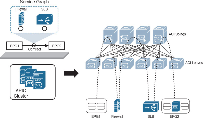
Notice in Figure 11-16 that the graph has two networking services: a firewall and a server load balancer (SLB). Regardless of whether they are physical or virtual, the ACI fabric is prepared to steer all traffic from EPG1 to EPG2 through the firewall and then through the SLB, while the return traffic will follow the inverse order.
In addition, APIC can also configure these devices through the use of device packages. This software piece allows APIC to expose configuration-specific parameters a service needs to work properly, such as firewall rules and load-balancing algorithms.
Cisco APIC
As a network controller, APIC was designed to provide a single point of control for an ACI fabric, maintaining the perception of the fabric as a system rather than a collection of switches. But contrarily to other SDN controllers, APIC does not participate on either the control plane or data plane of the fabric. For that reason, a complete APIC failure (or disconnection) does not interfere with the operations of applications that are already using the fabric. Running in ACI mode, the Nexus 9000 switches still maintain a high level of intelligence and performance, while APIC remains responsible for maintaining a complete representation of the fabric policies and managed objects.
To improve scalability and robustness, APIC is deployed as a cluster with 3 to 31 appliances. Because the APIC cluster is a central repository for the fabric, it deploys a special method named sharding to distribute ACI-related data across active APIC appliances, enhancing performance (less search processing) and replication requirements (smaller tables are exchanged between appliances).
The APIC architecture supports a massive scale for the ACI fabric, with future support of up to 1 million endpoints, 200,000 ports, and 64,000 tenants.
Note
These numbers represent the maximum future capacity of the ACI fabric according to its design at the time of this writing. Please refer to the ACI documentation on Cisco.com for the verified scalability information that is supported in the software and hardware versions you are using.
Fabric Management
The APIC cluster is also responsible for the management of an ACI fabric. Through its zero-touch discovery capabilities, Nexus 9000 switches and other APIC appliances are automatically included in the fabric through the use of Link Layer Discovery Protocol (LLDP).
Note
By default, each switch must be registered before it is added to the fabric. However, if the serial numbers of the switches are previously added to APIC, the discovery process can be greatly accelerated.
After the discovery, APIC handles all switch configurations, including IP addresses and boot image version.
Accordingly, the APIC cluster offers several access methods to manage an ACI fabric:
![]() GUI: Based on HTML5, the APIC GUI provides access to all ACI objects and policies. The interface also offers powerful tools such as the API inspector (which uncovers the API calls from GUI operations) and an object store browser to facilitate the integration of northbound applications. Figure 11-17 exhibits a fabric topology in the APIC GUI.
GUI: Based on HTML5, the APIC GUI provides access to all ACI objects and policies. The interface also offers powerful tools such as the API inspector (which uncovers the API calls from GUI operations) and an object store browser to facilitate the integration of northbound applications. Figure 11-17 exhibits a fabric topology in the APIC GUI.

![]() API: The APIC RESTful API is an extremely powerful interface that can fully leverage the ACI policy model. It has the option to expose and receive data in two formats (Extensible Markup Language [XML] and JavaScript Object Notation [JSON]). Figure 11-18 depicts an API navigator (Google’s POSTMAN) creating a tenant through the APIC API and using an XML-based request.
API: The APIC RESTful API is an extremely powerful interface that can fully leverage the ACI policy model. It has the option to expose and receive data in two formats (Extensible Markup Language [XML] and JavaScript Object Notation [JSON]). Figure 11-18 depicts an API navigator (Google’s POSTMAN) creating a tenant through the APIC API and using an XML-based request.

![]() CLI: APIC also offers a CLI with NX-OS-like commands and that also permits read-only access switches in the ACI fabric. As an add-on, the APIC CLI provides a Python-based scripting language for customized commands and operations. Example 11-1 exhibits a sample CLI session for your delight.
CLI: APIC also offers a CLI with NX-OS-like commands and that also permits read-only access switches in the ACI fabric. As an add-on, the APIC CLI provides a Python-based scripting language for customized commands and operations. Example 11-1 exhibits a sample CLI session for your delight.
! Starting a SSH session to APIC
login as: admin
Application Policy Infrastructure Controller
[email protected]'s password:
! Verifying the ACI components software version
admin@APIC1:~> show version
node type node id node name version
---------- ------- --------- --------------
controller 1 APIC1 1.1(1r)
controller 2 APIC1 1.1(1r)
controller 3 APIC1 1.1(1r)
leaf 101 Leaf1 n9000-11.1(1r)
leaf 102 Leaf2 n9000-11.1(1r)
spine 103 Spine1 n9000-11.1(1r)
spine 104 Spine2 n9000-11.1(1r)
! Starting a session to a switch
admin@APIC1:~> attach Leaf1
# Executing command: ssh N9K-L1
Password:
Last login: Thu Sep 10 19:39:54 2015 from apic1
Cisco Nexus Operating System (NX-OS) Software
TAC support: http://www.cisco.com/tac
Copyright (c) 2002-2015, Cisco Systems, Inc. All rights reserved.
[output suppressed]
! Verifying interface status
Leaf1# show interface brief
--------------------------------------------------------------------------------
Port VRF Status IP Address Speed MTU
--------------------------------------------------------------------------------
mgmt0 -- down unknown 9000
--------------------------------------------------------------------------------
Ethernet VLAN Type Mode Status Reason Speed Port
Interface Ch#
--------------------------------------------------------------------------------
Eth1/1 0 eth trunk down sfp-missing 10G(D) --
Eth1/2 0 eth trunk down sfp-missing 10G(D) --
Eth1/3 0 eth trunk up none 10G(D) --
Eth1/4 0 eth trunk up none 10G(D) --
[output suppressed]
Leaf1#
All APIC access methods are subordinated to an RBAC feature that can assign read or write access to different managed objects (such as tenants, application profiles, and so on) through local or remote accounts in TACACS+, RADIUS, or LDAP servers.
Integration
Natively, APIC disposes of multiple integration methods to other elements in an ACI fabric. One of the most important is OpFlex, an open and extensible protocol designed to transfer object-based connectivity policies (in XML or JSON) between a network policy controller (APIC, for example) and other devices such as
![]() Physical switches (leaves in an ACI fabric)
Physical switches (leaves in an ACI fabric)
![]() Virtual switches (virtual leaves in an ACI fabric)
Virtual switches (virtual leaves in an ACI fabric)
![]() Physical and virtual networking services (L4–L7 services in an ACI fabric)
Physical and virtual networking services (L4–L7 services in an ACI fabric)
OpFlex uses remote procedure calls as well as secure communication channels such as SSL and TLS. With the launch of ACI, Cisco has submitted OpFlex as an IETF draft and also as a supported OpenDaylight southbound interface. Using OpFlex, third-party vendors can also develop device packages, as previously mentioned in the section “Concerning Contracts.”
APIC also integrates with VM managers such as VMware vCenter, Microsoft System Center VMM, and OpenStack Nova. These special connections allow APIC to access information about hypervisors and VMs, become aware of VM live migrations, and push connectivity policies to VMs.
Finally, the APIC open API and policy model allows an ACI fabric to be controlled and consumed by automation tools such as Puppet, cloud management platforms such as Windows Azure Pack and OpenStack, and many other orchestration tools.
Visibility
Almost as a collateral effect of being a central point of management of an ACI fabric, APIC offers great visibility to administration users and northbound applications. Through its observer process, APIC is capable of monitoring hardware and software states from all managed switches, as well as the operational state of protocols, performance data, events, faults, and statistical collections. In addition, APIC maintains an endpoint registry that allows the monitoring of endpoints (directly connected, connected to an FEX, intermediate switches, or virtual switches).
The controller also provides health scores, a terrific tool for troubleshooting. In effect, these scores consist of dashboards built through ACI information collected by APIC to represent status elements such as
![]() ACI fabric
ACI fabric
![]() Managed devices
Managed devices
![]() Tenants
Tenants
![]() Application profiles
Application profiles
A health score aggregates data from state, drops, health score of dependent objects, latency, and remaining capacity through their faults and alerts. As an example of this monitoring tool, Figure 11-19 depicts the health score of a leaf switch.

A Peek into ACI’s Data Plane
From a data plane perspective, ACI is a VXLAN fabric with several enhancements and special characteristics to optimize its operations. In an ACI fabric, every switch is a VXLAN tunnel endpoint (VTEP), including both leaves and spines.
All connections between leaf and spine are routed (Layer 3), with APIC controlling the assignment of interface and VTEP addresses. A slightly modified version of IS-IS is responsible for advertising all VTEP addresses to all other switches in the fabric, leading to the creation of VXLAN tunnels between all VTEPs of the fabric.
Tip
The elements described (Layer 3 connections and VTEPs) belong to the infrastructure context.
Endpoints are assigned to EPGs depending on parameters that define the latter, which can include static values (VLAN, IP address, and port), as well as information from a VM manager, DHCP requests, ARP requests, and real traffic. After associating an endpoint to an EPG, the discovering leaf sends its information to the spines, which perform the role of “endpoint directory” (spine proxy) in the ACI fabric.
Within the fabric, the location of an endpoint corresponds to the VTEP to which it is connected. By definition, the communication between two endpoints is encapsulated into VXLAN packets exchanged by their respective VTEPs. Nonetheless, these internal VXLAN (iVXLAN) packets have special attributes that uniquely identify their source EPG. Additionally, the APIC-assigned VXLAN ID for each packet is correlated to a context (if the packet is routed) or to a bridge domain (if the packet is bridged).
To perform routing between two endpoints, ACI creates a distributed default gateway in each leaf with an administrator-configured IP address and an automatically assigned MAC address. Within such an arrangement, the ACI fabric always routes traffic destined to the default gateway MAC address and bridges traffic that is not destined for it.
By default, a unicast packet is normally forwarded between leaves through the APIC-assigned iVXLAN packets. As a result, ACI does not need to flood unknown unicast frames. If a leaf does not know the destination address on a packet, it will simply forward the packet to any proxy spine. Because the spines are aware of all endpoints, they can send the packet to the correct destination leaf, which in turn will locally cache the location (leaf VTEP) for the source endpoint.
Tip
Flooding can be enabled on a bridge domain if such behavior is desired for any reason.
Multicast and broadcast frames are forwarded to all VTEPs that are locally connected to the multicast group or source endpoint bridge domain, respectively. However, ARP frames are handled a bit differently: the leaf uses the destination IP in the ARP header to locate the destination leaf and directs the packet solely to it, avoiding unnecessary traffic to other leaves.
Because internal forwarding uses iVXLAN packets, which already identify source and destination endpoints, the original encapsulation (IEEE 802.1Q VLAN ID, VXLAN ID, or NVGRE ID) can be discarded for ingress packets and added to outgoing packets, as Figure 11-20 demonstrates.
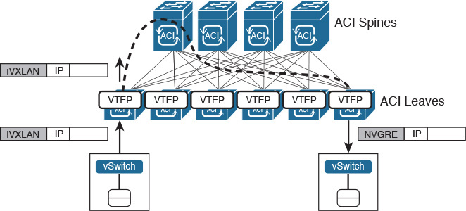
Through this unique normalization feature, the ACI fabric provides seamless communication between different hypervisors and physical servers. And much like the first Cisco routers provided communication between different types of network protocols, an ACI fabric can become the ultimate gateway for environments that have heterogeneous Layer 2 encapsulations.
Integration with Virtual Machine Managers
As previously mentioned, APIC has a special management connection with VM managers to provide the dynamic discovery of virtual endpoints. At the time of this writing, APIC supports integration with VMware vCenter, Microsoft SCVMM, and OpenStack Nova.
In the case of VMware vCenter, ACI offer two options for EPG assignment for virtual machines:
![]() VMware vNetwork Distributed Switch (vDS): APIC creates a distributed virtual switch in the vCenter cluster where each provisioned EPG automatically generates a distributed port group in the virtual switch. As ACI-generated port groups are assigned to VM network adapters, they are automatically assigned to their corresponding EPGs.
VMware vNetwork Distributed Switch (vDS): APIC creates a distributed virtual switch in the vCenter cluster where each provisioned EPG automatically generates a distributed port group in the virtual switch. As ACI-generated port groups are assigned to VM network adapters, they are automatically assigned to their corresponding EPGs.
![]() Cisco Application Virtual Switch (AVS): A Cisco distributed virtual switch controlled by APIC. AVS works as an ACI virtual leaf, performing local forwarding for intra-EPG traffic and iVXLAN encapsulation to physical ACI leaves for inter-EPG traffic.
Cisco Application Virtual Switch (AVS): A Cisco distributed virtual switch controlled by APIC. AVS works as an ACI virtual leaf, performing local forwarding for intra-EPG traffic and iVXLAN encapsulation to physical ACI leaves for inter-EPG traffic.
In the case of VMware vDS, ACI supports ESXi hosts that are directly connected to the ACI leaf, connected through a leaf-managed FEX, or connected through a single Layer 2 switch between host and leaf. Regardless of the connection method, ACI supports ESXi hosts with AVS as long as there is Layer 2 connectivity between AVS and an ACI leaf. For this reason, AVS is considered a fundamental piece in the integration process of an ACI fabric to an existing data center network infrastructure.
Figure 11-21 represents such an integration as well as some connection options for ESXi hosts.

As a bonus, Figure 11-21 also demonstrates that ACI leaves can deploy virtual PortChannels (vPCs) to external devices.
Around the Corner: OpenStack Neutron
Neutron is the OpenStack core project responsible for providing Network as a Service (NaaS) in these environments. Formerly known as Quantum, Neutron offers an API that enables cloud tenants to build fairly sophisticated networking topologies for multitier applications.
Innovation in Neutron is encouraged through API extensions and available plug-ins. These software elements allow open source development as well as integration of networking vendors to generate advanced policies (security, quality of service, monitoring, troubleshooting) and cloud networking services such as server load balancing (SLBaaS), firewalling (FWaaS), virtual private networking (VPNaaS), and data center interconnection (DCIaaS).
To build network topologies, OpenStack Neutron uses the following logical constructs:
![]() Tenant network: Within an OpenStack project, this element offers Layer 2 connectivity that is isolated to other projects. It may use a varied range of isolation technologies, including flat (all instances reside in the same network, which can be shared with the hosts), VLAN (use 802.1Q VLAN IDs), or overlay protocols such as VXLAN and GRE. OpenStack Neutron supports multiple projects and tenants having multiple private networks and enables them to choose their own IP addressing scheme, even if they overlap with other projects or tenants.
Tenant network: Within an OpenStack project, this element offers Layer 2 connectivity that is isolated to other projects. It may use a varied range of isolation technologies, including flat (all instances reside in the same network, which can be shared with the hosts), VLAN (use 802.1Q VLAN IDs), or overlay protocols such as VXLAN and GRE. OpenStack Neutron supports multiple projects and tenants having multiple private networks and enables them to choose their own IP addressing scheme, even if they overlap with other projects or tenants.
![]() Provider network: Created by the OpenStack administrator, this special network allows the communication of tenants to existing physical networks. It may use flat communication (untagged) or VLAN (802.1Q tag).
Provider network: Created by the OpenStack administrator, this special network allows the communication of tenants to existing physical networks. It may use flat communication (untagged) or VLAN (802.1Q tag).
![]() Subnet: Range of IP addresses which is also known as IP Address Management (IPAM). Neutron provides subnets for both tenant and provider networks.
Subnet: Range of IP addresses which is also known as IP Address Management (IPAM). Neutron provides subnets for both tenant and provider networks.
![]() Port: Virtual network connection point for a single device, such as the virtual NIC of a Nova instance. It exposes configuration and monitoring state for Neutron as well as other OpenStack components.
Port: Virtual network connection point for a single device, such as the virtual NIC of a Nova instance. It exposes configuration and monitoring state for Neutron as well as other OpenStack components.
![]() Router: Optional component that forwards IP packets between distinct networks. It can also offer Layer 3 services such as Network Address Translation (NAT) and access to external networks such as the Internet.
Router: Optional component that forwards IP packets between distinct networks. It can also offer Layer 3 services such as Network Address Translation (NAT) and access to external networks such as the Internet.
![]() Security group: Controls inbound and outbound traffic at the port level. It can be compared to access control lists in traditional network devices because it can specify type of traffic and direction. The default security group drops all ingress traffic and allows all egress traffic.
Security group: Controls inbound and outbound traffic at the port level. It can be compared to access control lists in traditional network devices because it can specify type of traffic and direction. The default security group drops all ingress traffic and allows all egress traffic.
These Neutron constructs are usually exposed to cloud tenants as an API or options on the Horizon GUI. At heart, they represent abstractions for the tenants that hide how networks are actually implemented. For example, a tenant will probably not know if a requested network is isolated from other tenants through VLAN or VXLAN because this choice is part of the Neutron administrator duties. As a direct consequence, there are many ways to provision networking resources for cloud tenants. One fairly typical deployment model is exposed in Figure 11-22.

Figure 11-22 identifies some of the most common nodes (which in effect are servers running OpenStack services):
![]() Network node: Deploys Layer 3 services (routers), a DHCP server for address assignment, and metadata containing all information about provisioned networks, tenants, projects, and IP addresses.
Network node: Deploys Layer 3 services (routers), a DHCP server for address assignment, and metadata containing all information about provisioned networks, tenants, projects, and IP addresses.
![]() Compute node: Hosts Nova instances that use Neutron-provisioned networking resources.
Compute node: Hosts Nova instances that use Neutron-provisioned networking resources.
![]() Controller node: Runs core OpenStack services such as Nova and, of course, Neutron.
Controller node: Runs core OpenStack services such as Nova and, of course, Neutron.
In the implementation depicted in Figure 11-22, while all core services receive API calls from the API network, they use the management network to control their corresponding agents in the compute and network nodes. Nova instances use the data network to exchange local traffic and access Layer 3 services in the controller node. Finally, the external network is used to allow these instances to access an outside network such as the Internet.
Whereas these networks commonly use statically provisioned VLANs in the physical network infrastructure, the data network usually carries VXLAN or GRE packets to segment traffic among Nova instances from different projects or tenants.
One of the main drawbacks from this model resides in the network node, whose performance can be seriously challenged with routing and frame encapsulation processes. This obstacle can be surmounted by installing on a Neutron agent plug-ins and drivers that allow API requests to be converted into configurations that are deployed on hardware-based network devices. While a plug-in represents a group of general functionalities, a driver contains the necessary code to allow plug-in functions in a specific technology or device.
Originally, Neutron had native plug-ins for Open vSwitch and Linux Bridge, because they are very common in OpenStack environments. However, these plug-ins were eventually replaced by the Modular Layer 2 (ML2) plug-in, which essentially creates broadcast domains for Nova instances in generic Layer 2 devices.
Cisco has developed an ML2 driver for most Nexus switches in order to provision VLANs on networks based on these platforms. Additionally, Cisco has created an APIC ML2 driver that leverages the ACI policy model to bring several advantages to OpenStack implementations. With this driver, API requests received on Neutron automatically provision ACI logical constructs, as Table 11-5 describes.

Figure 11-23 depicts such integration in action.

Using this driver, ACI introduces significant advantages such as routing capabilities (avoiding the use of the network node for this objective), topology independency (through APIC), multi-tenancy (with address overlap), and instance mobility.
In a joint effort with other network vendors, Cisco has accelerated innovation on Neutron, introducing the Group-Based Policy (GBP) concept to OpenStack. This initiative intends to counterpoint one main disadvantage from the traditional Neutron approach: the networking properties of a VM are defined through dispersed objects (network for Layer 2, router for Layer 3, and security groups for security). As a result, this traditional OpenStack model increases complexity for automation processes because inconsistencies may happen as networking characteristics are updated.
GBP addresses this problem through a network abstraction model based on the following objects:
![]() Group: Represents a set of network endpoints that share the same network properties and must be handled the same way by the network.
Group: Represents a set of network endpoints that share the same network properties and must be handled the same way by the network.
![]() Policy rule set: Reusable set of network rules that describe allowed traffic between two groups. It is basically composed of policy classifiers converted into policy rules.
Policy rule set: Reusable set of network rules that describe allowed traffic between two groups. It is basically composed of policy classifiers converted into policy rules.
![]() Layer 2 policy: Defines a broadcast domain.
Layer 2 policy: Defines a broadcast domain.
![]() Layer 3 policy: Defines the forwarding between two different IP subnets.
Layer 3 policy: Defines the forwarding between two different IP subnets.
Table 11-6 represents the intentional correspondence between GBP and ACI managed objects.

Note
At the time of this writing, Cisco is also developing an OpFlex agent for Open vSwitch, allowing this device to act as an ACI virtual leaf inside of a compute node. In addition to APIC’s role as enforcer of all ACI policies locally on these nodes, the OpFlex plug-in also allows APIC to become the consolidated point of integration for the OpenStack Neutron server.
Figure 11-24 represents this integration scenario.

Further Reading
![]() OpenStack Networking Guide, “Overview and Components”: http://docs.openstack.org/networking-guide/intro_os_networking_overview.html
OpenStack Networking Guide, “Overview and Components”: http://docs.openstack.org/networking-guide/intro_os_networking_overview.html
![]() Installing the Cisco APIC OpenStack Driver: http://www.cisco.com/c/en/us/td/docs/switches/datacenter/aci/apic/sw/1-x/api/openstack/b_Cisco_APIC_OpenStack_Driver_Install_Guide.html
Installing the Cisco APIC OpenStack Driver: http://www.cisco.com/c/en/us/td/docs/switches/datacenter/aci/apic/sw/1-x/api/openstack/b_Cisco_APIC_OpenStack_Driver_Install_Guide.html
![]() Group-Based Policy for OpenStack: https://wiki.openstack.org/w/images/a/aa/Group-BasedPolicyWhitePaper_v3.pdf
Group-Based Policy for OpenStack: https://wiki.openstack.org/w/images/a/aa/Group-BasedPolicyWhitePaper_v3.pdf
Exam Preparation Tasks
Review All the Key Topics
Review the most important topics in this chapter, denoted with a Key Topic icon in the outer margin of the page. Table 11-7 lists a reference of these key topics and the page number on which each is found.

Table 11-7 Key Topics for Chapter 11
Complete the Tables and Lists from Memory
Print a copy of Appendix B, “Memory Tables” (found on the CD), or at least the section for this chapter, and complete the tables and lists from memory. Appendix C, “Answers to Memory Tables,” also on the CD, includes completed tables and lists so that you can check your work.
Define Key Terms
Define the following key terms from this chapter, and check your answers in the glossary:
Software-Defined Networking (SDN)
Application Centric Infrastructure (ACI)
Application Policy Infrastructure Controller (APIC)