
Chapter 5. Server Virtualization
This chapter covers the following topics:
![]() Introduction to Servers and Operating Systems
Introduction to Servers and Operating Systems
![]() Server Virtualization Definitions
Server Virtualization Definitions
![]() Server Virtualization Features
Server Virtualization Features
![]() Cloud Computing and Server Virtualization
Cloud Computing and Server Virtualization
This chapter covers the following exam objectives:
![]() 3.2 Describe Server Virtualization
3.2 Describe Server Virtualization
![]() 3.2.a Basic knowledge of different OS and hypervisors
3.2.a Basic knowledge of different OS and hypervisors
Throughout the history of computing, virtualization technologies have offered solutions to diverse problems such as hardware inefficiency and lack of support for legacy applications. More recently, the accelerated adoption of server virtualization on x86 platforms in the mid-2000s has clearly positioned such a trend as one of the most important components of modern data center architecture.
And without surprise, cloud computing significantly benefits from the agility and flexibility virtualization brings to application server provisioning. Therefore, the CLDFND exam requires a basic knowledge of operating systems and hypervisors. Accordingly, this chapter covers these concepts as well as important definitions that establish the overall context of server virtualization.
This chapter also introduces the main components of server hardware and explores how some of the challenges of server hardware are solved through virtualization. Then, it addresses the most important concepts related to x86 server virtualization, introduces the most prominent hypervisor architectures available at the time of this writing, and identifies virtualization features that are particularly useful in cloud computing environments.
“Do I Know This Already?” Quiz
The “Do I Know This Already?” quiz allows you to assess whether you should read this entire chapter thoroughly or jump to the “Exam Preparation Tasks” section. If you are in doubt about your answers to these questions or your own assessment of your knowledge of the topics, read the entire chapter. Table 5-1 lists the major headings in this chapter and their corresponding “Do I Know This Already?” quiz questions. You can find the answers in Appendix A, “Answers to Pre-Assessments and Quizzes.”
1. Which of the following is not a server hardware component?
a. Storage controller
b. NIC
c. Operating system
d. CPU
e. RAM
2. Which of the following is not a server operating system?
a. Microsoft Windows Server
b. FreeBSD
c. Cisco IOS
d. Linux
3. Which of the following advantages were achieved through mainframe virtualization in the early 1970s? (Choose two.)
a. Performance increase
b. Legacy application support
c. Downsizing
d. User isolation
4. Which of the following is not an advantage from server virtualization on x86 servers? (Choose all that apply.)
a. Hardware efficiency
b. Network provisioning
c. Legacy application support
d. Management cost decrease
5. Which of the following are Type-1 hypervisors? (Choose all that apply.)
a. Linux KVM
b. Xen
c. Microsoft Hyper-V
d. VMware Workstation
6. Which of the following identify a hypervisor and its corresponding VM manager? (Choose all that apply.)
a. KVM and oVirt
b. vSphere and ESXi
c. Hyper-V and Hyper-V Manager
d. ESXi and vCenter
e. KVM and OpenStack Nova
7. Which of the following is not a virtual machine file?
a. Virtual disk
b. NVRAM
c. Swap memory
d. NFS
e. Log
8. Which of the following statements is false?
a. VM high availability enables the restarting of virtual machines that were running on hosts that failed.
b. Live migration is a disaster recovery feature that allows the migration of VMs after a physical server suffers a major hardware failure.
c. Resource load balancing allows automatic host selection when you are creating a virtual machine.
d. VM fault tolerance reserves double the resources a virtual machine requires.
9. In which of the following features is a disruption in associated virtual machines expected?
a. Fault tolerance
b. Live migration
c. High availability
d. Resource load balancing
10. Which of the following features enables cloud computing pooling characteristics?
a. Fault tolerance
b. Live migration
c. High availability
d. Resource load balancing
Foundation Topics
Introduction to Servers and Operating Systems
In Chapter 2, “Cloud Shapes: Service Models,” you learned the different ways in which a cloud computing environment can offer services. Testing your memory further, a specific service model called Infrastructure as a Service (IaaS) provides server instances to end users, allowing them to potentially run any software on top of these structures.
This section revisits the formal definition of a server, aiming to provide you with a strong conceptual background before you delve into their positioning and challenges in cloud computing environments.
What Is a Server?
Generically speaking, a server is a software component that can accept requests from multiple clients, providing suitable responses after processing these requests or accessing other servers. This definition relates to the popular client/server application architecture, which eventually replaced the centralized architecture based on mainframes during the last two decades of the 20th century.
Although server software may run on desktop computers, its increasing relevance to business applications means that dedicated, specialized hardware is better suited to host these central application components. In the context of data center infrastructure, these customized micro-computers running server software are also (confusingly) called servers.
Note
As you advance in your study in cloud technologies, you will learn that distinct data center technology teams may use the exact same term for different subjects. Therefore, I highly recommend that you always try to discover the context of the discussion beforehand (for example, software or hardware, in the case of the word “server”). Except when noted, “server” in this chapter refers to the dedicated hardware that hosts server applications.
Data centers, be they for cloud deployments or not, are basically built for application hosting and data storing. Suitably, data center architects may view servers as raw material that ultimately defines how a data center is designed and maintained. In fact, I know many companies that measure their data center agility according to the answer to the following question: How long does it take to provision an application server?
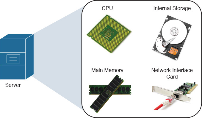
Of course, servers have different characteristics depending on the applications they are hosting. However, they all share the following basic components:

![]() Central processing unit (CPU): Unquestionably the most important component of any computer, the CPU (aka processor) is responsible for the majority of processing jobs and calculations. The CPU is probably the server component that has experienced the fastest evolution.
Central processing unit (CPU): Unquestionably the most important component of any computer, the CPU (aka processor) is responsible for the majority of processing jobs and calculations. The CPU is probably the server component that has experienced the fastest evolution.
![]() Main memory: The CPU uses these fast, volatile storage areas to directly access data retrieved from files and programs that are being worked on. If you picture yourself as the CPU, the main memory would be your desk, stacking documents that you are working on at this very moment or in a few minutes. Main memory can be also referred to as random-access memory (RAM), mainly because the CPU can possibly access any part of it.
Main memory: The CPU uses these fast, volatile storage areas to directly access data retrieved from files and programs that are being worked on. If you picture yourself as the CPU, the main memory would be your desk, stacking documents that you are working on at this very moment or in a few minutes. Main memory can be also referred to as random-access memory (RAM), mainly because the CPU can possibly access any part of it.
![]() Internal storage: Most servers have an internal device that allows the recording and reading of data for multiple purposes such as loading the operating system and storing application information. The most usual internal storage devices are hard drives, which can be managed by special cards called storage controllers.
Internal storage: Most servers have an internal device that allows the recording and reading of data for multiple purposes such as loading the operating system and storing application information. The most usual internal storage devices are hard drives, which can be managed by special cards called storage controllers.
Note
In Chapters 8 and 9 (“Block Storage Technologies” and “File Storage Technologies”), I will explore the multiple available storage technologies for cloud computing deployments.
![]() Network interface controller (NIC): This is a hardware device that controls the communication between a server and the network. The vast majority of NICs deploy Ethernet, a protocol so popular that it is commonplace to find native Ethernet interfaces in the server motherboard (circuit board that physically contains all the computer components). In respect to both scenarios, some authors consider network adapter to be a more appropriate moniker than network interface controller for representing them.
Network interface controller (NIC): This is a hardware device that controls the communication between a server and the network. The vast majority of NICs deploy Ethernet, a protocol so popular that it is commonplace to find native Ethernet interfaces in the server motherboard (circuit board that physically contains all the computer components). In respect to both scenarios, some authors consider network adapter to be a more appropriate moniker than network interface controller for representing them.
![]() Peripherals: These are auxiliary devices that perform particular functions such as data input, output, or specialized processing. Some examples are the CD/DVD drive, mouse, keyboard, and printer, among many others.
Peripherals: These are auxiliary devices that perform particular functions such as data input, output, or specialized processing. Some examples are the CD/DVD drive, mouse, keyboard, and printer, among many others.
Figure 5-1 displays these server hardware components.
Of course, there are many other server elements such as BIOS (basic input/output system), the discussion of which is out of the scope of this chapter. But most of them owe their obscurity to a very special piece of software that will discussed in the next section.
Note
You will find more details about BIOS and other components of x86 servers in Chapter 12, “Unified Computing”.
Server Operating Systems
An operating system (or simply OS) can be defined as software that controls computer resources and provides common services for other computer programs that run “on top of it.” Consequently, the operating system is widely considered the most fundamental piece of software in a computer system.
Table 5-2 describes some of the most popular operating systems at the time of this writing.


The kernel (“core” in German) is the central part of an operating system. This program directly manages the computer hardware components, such as memory and CPU. The kernel is also responsible for providing services to applications that need to access any hardware component, including NICs and internal storage.
Because it represents the most fundamental part of an operating system, the kernel is executed on a protected area of the main memory (kernel space) to prevent problems other processes may cause. Therefore, non-kernel processes are executed in a memory area called user space.
As a visual aid, Figure 5-2 illustrates how an OS kernel relates to applications and the computer hardware.

Operating systems can be categorized according to the distribution of their components between kernel space and user space. Hence, operating systems whose entire architecture resides in kernel space are called monolithic (for example, Linux and FreeBSD). By contrast, microkernel operating systems are considered more flexible because they consist of multiple processes that are scattered across both kernel space and user space. Mac OS X and current Windows versions are examples of microkernel operating systems.
A server operating system is obviously focused on providing resources and services to applications running on server hardware. Such is the level of specialization of these OSs that many nonessential services, such as the GUI, may unceremoniously be disabled during normal operations.
Server Virtualization History
Contrary to a common misconception among many IT professionals, virtualization technologies are not exclusive to servers or even cutting-edge 21st-century innovations.
As a generic term, virtualization can be defined as the transparent emulation of an IT resource to provide to its consumers benefits that were unavailable in its physical form. Thereupon, this concept may be embraced by many resources, such as network devices, storage arrays, or applications.
When virtualization was originally applied to computer systems, several advantages were achieved in two different platforms, as you will learn in the next sections.
Mainframe Virtualization
Famously described in Moore’s law back in 1965, and still true today, hardware development doubles performance and capacity by each period of 24 months. From time to time, these developments require changes in the software stack, including the operating system and application components. Understandably, these software pieces may have deeper links with specific processor architectures and may simply not work (or lose support) with a hardware upgrade.
To counteract the effect of this trend on its mainframe series, IBM released the Virtual Machine Control Program (VM-CP) in 1972, with widespread adoption within its customer base. Figure 5-3 lists the main components of this successful architecture.

As displayed in Figure 5-3, the Control Program (CP) controlled the mainframe hardware, dedicating a share of its hardware resources to each instance of the Conversational Monitor System (CMS). As a result, each CMS instance conjured an abstraction that gave each mainframe user the perception of accessing an exclusive operating system for his own purposes. This architecture coined the term virtual machine (VM), which essentially was composed of a CMS instance and all the user programs that were running on that instance.
Since its first commercial release, mainframe virtualization has brought several benefits to these environments, such as:
![]() User isolation: Through the creation of virtual machines, VM-CP protected multiple independent user execution environments from each other.
User isolation: Through the creation of virtual machines, VM-CP protected multiple independent user execution environments from each other.
![]() Application legacy support: With VM-CP, each user had access to an environment that could emulate one particular version of operating system and hardware combination. Consequently, during a migration to a new hardware version, a virtual machine could be easily created to host applications from a previous mainframe generation.
Application legacy support: With VM-CP, each user had access to an environment that could emulate one particular version of operating system and hardware combination. Consequently, during a migration to a new hardware version, a virtual machine could be easily created to host applications from a previous mainframe generation.
This approach is still used today in modern mainframe systems, even enabling these systems to execute operating systems that were developed for other platforms, such as Linux.
Virtualization on x86
The generic term “x86” refers to the basic architecture from computers that used the Intel 8086 processor and its subsequent generations (80286, 80386, 80486, and so on). Its wide adoption in PCs and “heavy” workstations paved the way for the popularization of the architecture in data centers, coalescing with the client/server architecture adoption that started in the 1980s. With the advent of web-based application technologies in the 1990s, many developers successfully migrated to using x86 platforms as opposed to IBM mainframes and Reduced Instruction Set Computing (RISC) computers from Sun Microsystems, DEC, Hewlett-Packard, and IBM.
During this transition, best practices at the time advised that each application component, such as a web service or database software, should have a dedicated server. This ensured proper performance control and smaller impacts in the case of a hardware failure.
Following this one-application-per-server principle, server hardware acquisition was chained to the requirements of new application deployments. Hence, for each new software component, a corresponding server was bought, installed, and activated.
Soon, this approach posed its share of problems, including low efficiency. For example, the capacity of email servers was sized based on utilization peaks that occurred when employees arrived at the office and returned from lunch. As a result, multiple servers remained practically unused for most of their lifetime.
As more diverse applications were deployed, the sprawling army of poorly utilized servers pushed data centers to inescapable physical limits, such as power and space. Paradoxically, companies were expanding their data center footprint, or even building new sites, while their computing resources were extremely inefficient.
Founded in 1998, VMware applied the principles of mainframe virtualization to x86 platforms, allowing a single micro-computer to easily deploy multiple virtual machines. At first, VMware provided solutions focused on workstation virtualization, where users could create emulated desktops running other versions of operating systems on their machines.
At the beginning of the 2000s, VMware successfully ported this technology to server hardware, introducing the era of server virtualization. Leveraging a tighter integration with virtualization features offered by Intel and AMD processors and the increasing reliability from x86 servers, virtual machines could now offer performance levels comparable to those of physical servers.
Figure 5-4 depicts how server virtualization improved data center resource efficiency during this period.

As you can see, server virtualization software enables applications that were running on dedicated physical servers to be migrated to virtual machines. A virtualization administrator decides how many virtual machines a virtualized server can host based on its hardware capacity, but undoubtedly reaching a much higher efficiency level with multiple different workloads.
Besides a better use of hardware resources, server virtualization on x86 platforms also inherited the benefit of supporting applications developed for legacy hardware architectures. A remarkable example happened during the architecture evolution from 32-bit to 64-bit, which also occurred in the early 2000s. In the 32-bit architecture, the CPU refers to a memory location using 32 bits, resulting in a maximum memory size of 4 GB. To overcome this constraint, both Intel and AMD ignited architecture designs with 64-bit addresses, allowing a much higher memory limit.
During this transition period, many IT departments could not take advantage of the performance boost from new servers simply because too many changes would be required to adapt applications that were originally developed for 32-bit operating systems. Server virtualization overcame this challenge, supporting 32-bit virtual machines to run over 64-bit virtualized servers, with practically no software alteration during this process.
As you will learn in the section “Server Virtualization Features” later in this chapter, server virtualization evolution unleashed many gains that were simply inconceivable to mainframe virtualization pioneers. However, to fully grasp the importance of server virtualization for cloud computing, you must delve even deeper into its main fundamentals.
Server Virtualization Definitions
As server virtualization increased hardware consolidation and offered application legacy support, it naturally became an integral part of modern data center architectures. And VMware’s competition increased as well, as other software vendors entered the server virtualization market with interesting solutions and slightly different approaches.
To approach server virtualization as generically and vendor neutrally as possible, in the following sections I will focus on the common concepts that bind all virtualization solutions and introduce hypervisor offerings from many different vendors.
Hypervisor
A hypervisor can be defined as a software component that can create emulated hardware (including CPU, memory, storage, networking, and peripherals, among other components) for the installation of a guest operating system. In the context of server technologies, a hypervisor is essentially a program that allows the creation of virtual servers.
Table 5-3 lists and describes the most commonly deployed hypervisors at the time of this writing.

Hypervisor Types
As Table 5-3 indicates, not all hypervisors are alike. Nonetheless, they can be divided in two basic categories, as shown in Figure 5-5.

For comparison purposes, Figure 5-5 represents a virtualization host (physical server) as a stack composed of hardware, an operating system, and a single application. To its right, a Type-1 hypervisor replaces the operating system as the software component that directly controls the hardware, and for this reason it is also known as a native or bare-metal hypervisor. Type-1 hypervisors are heavily used for server virtualization and are exemplified by the first six solutions listed in Table 5-3. On the other hand, as shown on the far right, a Type-2 hypervisor runs over a preexisting operating system. When compared to Type-1 hypervisors, these hypervisors are considered easier to use, but the trade-off is that they offer lower performance levels, explaining why they are normally deployed for workstation virtualization. Also known as hosted hypervisors, this category is represented by the last four solutions listed in Table 5-3.
Note
These categories follow a classification system developed by Gerald J. Popek and Robert P. Goldberg in their 1974 article “Formal Requirements for Virtualizable Third Generation Architectures.” By the way, as a healthy exercise, which type of hypervisor is VM-CP (introduced earlier in the section “Mainframe Virtualization”)?
Virtual Machines
In the context of modern server virtualization solutions, a virtual machine is defined as an emulated computer that runs a guest operating system and applications. Each VM deploys virtual hardware devices such as the following (see Figure 5-6):
![]() Virtual central processing unit (vCPU)
Virtual central processing unit (vCPU)
![]() Virtual random-access memory (vRAM)
Virtual random-access memory (vRAM)
![]() Virtual hard drive
Virtual hard drive
![]() Virtual storage controller
Virtual storage controller
![]() Virtual network interface controller (vNIC)
Virtual network interface controller (vNIC)
![]() Virtual video accelerator card
Virtual video accelerator card
![]() Virtual peripherals such as a CD, DVD, or floppy disk drive
Virtual peripherals such as a CD, DVD, or floppy disk drive

These components perform the same functions as their physical counterparts.
In addition to the devices in the preceding list, Figure 5-6 displays a proprietary virtual device called VMCI (Virtual Machine Communication Interface), which can provide fast communication between virtual machines and the ESXi kernel.
Allow me to give away the “secret sauce” of x86 virtualization: from the hypervisor standpoint, a VM is composed of a set of files residing on a storage device. Figure 5-7 displays some actual files that define the same VM hosted on VMware ESXi.

In essence, these files dictate how the hypervisor controls the physical resources and shares them with the guest operating system in each VM. The following are the main VM file types in VMware ESXi:
![]() Virtual disk (.vmdk extension): This file contains all the data a VM uses as its internal storage device.
Virtual disk (.vmdk extension): This file contains all the data a VM uses as its internal storage device.
![]() Swap memory (.vswp extension): This file is used as a replacement for the virtual memory whenever the processes running on the VM reach the vRAM predefined limit.
Swap memory (.vswp extension): This file is used as a replacement for the virtual memory whenever the processes running on the VM reach the vRAM predefined limit.
![]() Log (.log extension): These files store all the information a VM produces for troubleshooting purposes.
Log (.log extension): These files store all the information a VM produces for troubleshooting purposes.
![]() Configuration (.vmx extension): You can find all the hardware settings for a VM in this file, including vRAM size, NIC information, and references to all the other files.
Configuration (.vmx extension): You can find all the hardware settings for a VM in this file, including vRAM size, NIC information, and references to all the other files.
![]() Nonvolatile RAM (.nvram extension): This file contains information used during the VM initialization, such as the boot device order and CPU settings.
Nonvolatile RAM (.nvram extension): This file contains information used during the VM initialization, such as the boot device order and CPU settings.
While other hypervisors certainly use different file extensions to represent a virtual machine, most of them share this architectural structure.
Virtual Machine Manager
A virtual machine manager (VM manager) is a software solution that can create and manage virtual machines on multiple physical servers running hypervisors. In this context, a virtualization cluster can be defined as a group of centrally managed hosts.
To deploy a robust virtualization cluster, the VM manager should be redundant. However, as you will learn in the section “Server Virtualization Features,” if you deploy the VM manager as a virtual machine, it can leverage several availability features from its own virtualization cluster.
Now that you know what hypervisors have in common, it is time to take a look at their main distinctions, tools, and deployment models.
Hypervisor Architectures
As previously mentioned, many competing solutions were developed after VMware created the server virtualization market for x86 platforms. Broadly speaking, the hypervisor architectures discussed in the following sections offer distinct benefits for environments that are directly aligned to their origins: VMware vSphere (workstation virtualization), Microsoft Hyper-V (Windows operating system), and Linux KVM (open source operating system). You will learn the details of how each solution deploys virtual machines and discover the main components behind their architectures.
VMware vSphere
VMware vSphere is the software suite comprising the VMware ESXi hypervisor and its associated tools. VMware developed vSphere for the purpose of creating and managing virtual servers. Continuing the basic structure started with VMware Infrastructure (VI), vSphere has maintained its position as the leading server virtualization architecture since its launch in 2009.
Figure 5-8 depicts the main components of the VMware vSphere architecture and how they interact with each other.

As Figure 5-8 demonstrates, a virtualization administrator uses vSphere Client, which is software available for Windows computers, to deploy multiple virtual machines on hosts with installed ESXi hypervisors. Nevertheless, the use of a VM manager enables multiple benefits besides the centralized creation of VMs, as you will learn in the upcoming section “Server Virtualization Features.” Originally built over a Windows-based server, VMware vCenter is the VM manager for the vSphere suite.
A VMware vSphere administrator can use a web browser to control VMware vCenter and, consequently, its associated virtualization cluster.
Note
In VMware vSphere terminology, “cluster” refers to a set of hosts that share the same policies and feature settings. Therefore, a single vCenter instance can manage multiple clusters. However, for the sake of simplicity, this certification guide refers to a virtualization cluster as a single VM manager managing a set of hosts.
Microsoft Hyper-V
Microsoft, the leading personal computer operating system vendor, released its server virtualization offer in 2008. Hyper-V is a hypervisor enabled as a new Windows Server 2012 role, exactly as you would activate services such Active Directory or Terminal Services in this operating system. Figure 5-9 shows Hyper-V already installed and activated along with other roles in a Windows 2012 Server.
Your first impression might be that Hyper-V is a Type-2 hypervisor, but Hyper-V is indeed a Type-1 hypervisor because it has direct access to the server hardware. In fact, after the Hyper-V role is enabled on a Windows 2012 Server, the whole system requires a reboot so the original operating system instance can be transformed into a special virtual machine, formally called a parent partition. For obvious reasons, Hyper-V grants special privileges to this partition because it also deploys some functions that are shared by the hosted VMs.

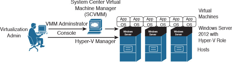
Although a virtualization administrator can use client software called Hyper-V Manager to create and manage VMs in a single Hyper-V host, System Center Virtual Machine Manager (SCVMM) is the architecture VM manager, extending server virtualization features to multiple hosts. Using the VMM Administrator Console, a virtualization administrator can control a Hyper-V virtualization cluster as depicted in Figure 5-10.
Microsoft Hyper-V has increased its participation in the server virtualization market with each new version. Arguably, its adoption is strongly supported by the ubiquitous presence of the Windows operating system in server environments and its relative operational simplicity to Windows-trained professionals.
Linux Kernel-based Virtual Machine
Standing on the shoulders of a giant called open source development, server virtualization was brought to Linux systems with the increasing adoption of this operating system in the 2000s. Kernel-based Virtual Machine (KVM) is arguably the most popular solution among several other Linux-based Type-1 hypervisors since its release in 2007.
As its name implies, this full virtualization solution is not executed as a user application but actually as a loadable kernel module called kvm.ko. This component was integrated in mainline Linux since version 2.6.20.
Both the open source community and vendors packaging Linux enterprise solutions have developed a great variety of methods to manage KVM virtual machines, including command-line interfaces (Linux shell), web interfaces, and client-based GUIs. Additionally, many VM managers were similarly created to manage KVM-based virtualization clusters. Among these are Red Hat Enterprise Virtualization (RHEV), oVirt, and OpenStack Nova. Figure 5-11 illustrates how all of these components are integrated into a generic KVM architecture.

KVM has been adopted for various reasons, such as cost (it can be considered free, depending on your version of Linux) and operational easiness to install in server environments where Linux expertise is available.
Note
OpenStack Nova encompasses many functions that are beyond the scope of a VM manager. Thus, besides the creation and management of virtual machines (called “Nova instances”), Nova is considered the de facto orchestrator of most computer-related operations in an OpenStack cloud, offering a set of APIs (including Amazon EC2 API) to automate pools of computer resources from hypervisors such as Hyper-V, VM managers (such as VMware vCenter), and high-performance computing (HPC) clusters.
Multi-Hypervisor Environments
While the three software solutions explained in the previous sections arguably represent the most widely adopted server virtualization architectures, they are not alone in this market. Some other hypervisors, such as Citrix XenServer, were briefly described in Table 5-3.
For obvious reasons, each solution presents its own specific advantages. Yet, some customers do not want to be restricted to a single server virtualization architecture. Interestingly, during the past few years, I have observed an increasing number of customers deploying multi-hypervisor environments for various reasons. For example:
![]() To avoid vendor lock-in
To avoid vendor lock-in
![]() To leverage personnel’s specialized familiarity with a specific operating system
To leverage personnel’s specialized familiarity with a specific operating system
![]() To deploy new projects such as cloud computing or virtual desktops
To deploy new projects such as cloud computing or virtual desktops
Server Virtualization Features
As I briefly mentioned in the section “Virtualization on x86,” a server virtualization cluster can bring more benefits to data centers than simply creating and monitoring virtual machines on multiple hosts. With the objective of exploring these enhancements, the following sections discuss this list of features (plus a few other interesting features):
![]() Virtual machine high availability
Virtual machine high availability
![]() Virtual machine live migration
Virtual machine live migration
![]() Resource load balancing
Resource load balancing
![]() Virtual machine fault tolerance
Virtual machine fault tolerance
Undoubtedly, these features highlight the fact that VMs are software constructs that can be much more easily manipulated when compared to physical servers.
Allow me to suggest to you a small exercise: During the explanation of each feature, try to picture how it can help cloud computing environments. Later, in the section “Cloud Computing and Server Virtualization,” I will address these synergies so you can gauge your cloud design powers.
Virtual Machine High Availability
Server failures may happen at any time. To protect server systems from such events, application teams usually have to develop or acquire solutions that provide an adequate level of resiliency for these systems. These solutions are generically called cluster software and are usually bound to an operating system (e.g., Windows Server Failover Cluster) or a single application (e.g., Oracle Real Application Clusters).
With the considerable variety of operating systems and their hosted applications, the job of managing cluster software in pure physical server environments can become extremely difficult. Notwithstanding, through virtualization clusters, hypervisors can actually provide high availability to virtual machines regardless of their application or operating system flavors.
Figure 5-12 details how selected virtual machines can be conveniently “resurrected” whenever their host suffers a major hardware or hypervisor failure.

In the situation depicted on the left side of Figure 5-12, a virtualization cluster consists of three hosts (Host1, Host2, and Host3) with two virtual machines each. After Host1 experiences a major failure, both of its virtual machines are restarted on other hosts from the same cluster, as shown on the right. This automatic procedure is only possible because the affected VMs’ files are stored on an external storage system (such as a disk array or network-attached storage) rather than a hard disk on Host1.
Both disk arrays and network-attached storage (NAS) will be properly explained in Chapters 8 and 9. But at this stage, you simply need to understand that these systems represent external storage devices that can be accessed by multiple servers, such as hosts on the same virtualization clusters.
VM high availability (HA) is extremely useful for legacy applications that do not have any embedded availability mechanism. As a consequence, this specific enhancement allows less development effort if, of course, the application service-level agreement (SLA) supports a complete reboot.
Virtual Machine Live Migration
A much-hyped virtualization innovation in the mid-2000s, live migration enables the transport of a virtual machine between two hosts from a virtualization cluster with minimal disruptions in its guest OS and hosted applications.
Figure 5-13 details how this elegant sleight of hand actually occurs.
In Figure 5-13, the virtualization administrator decides that a virtual machine must move from Host1 to Host2 using live migration. Accordingly, the VM manager communicates to both hosts about the operation. Immediately after Host2 creates a copy of the soon-to-be-migrated VM, Host1 starts a special data connection to Host2 to synchronize the VM state until Host2 has an exact copy of the VM (including its main memory and, consequently, end-user sessions). After the synchronization is completed, the VM copy is fully activated while its original instance is abruptly discarded.

Figures 5-14 and 5-15 detail the live migration procedures in a VMware vSphere environment, which is called vMotion in this architecture. For your information, the whole process took approximately 4 seconds.


Figure 5-14 displays a possible method to start the live migration of VM-Nomad, currently running on host10, to host11. Using vSphere Client, I right-clicked the VM name and selected the option Migrate.
Figure 5-15 displays the result of the whole process. Notice that I have also started an ICMP Echo test (ping) from my desktop directed to the VM to verify if the migration causes any loss of connectivity. And although it does impact a single ICMP Echo in the series, the migration is practically imperceptible to a TCP connection due to its native reliability mechanisms.
Also observe that, similarly to virtual machine HA, the live migration process is possible because the VMs’ files are located in a shared storage system.
Note
Recently, some hypervisor vendors have overcome this limitation. Deploying a concept called Shared Nothing Live migration, the whole set of VM files (including virtual disk) is copied between hosts before the machine state is synchronized. While this technique eliminates the requirement for a shared external storage system, you should expect the whole migration to be completed after a few minutes, not seconds as with standard live migrations.
One very important point: VM live migration is definitely not a disaster recovery feature simply because it is a proactive operation rather than a reaction to a failure. On the other hand, several data center architects consider live migration a disaster avoidance technique that allows VMs to be vacated from hosts (or even sites) before a predicted major disruption is experienced.
Resource Load Balancing
The degree of flexibility introduced by live migrations has fostered an impressive toolbox for automation and capacity planning. One of these tools, resource load balancing, enables hosts that may be on the verge of a predefined threshold to preemptively send virtual machines to other hosts, allowing an optimal utilization of the virtualization cluster’s overall resource capacity.
Figure 5-16 shows an example of a resource load balancing activity in a virtualization cluster.

In Figure 5-16, Host1 presents a 95% utilization of a hardware resource (for example, CPU or memory). Because the VM manager is monitoring every resource on cluster hosts, it can proactively take an automated action to migrate virtual machines from Host1 to Host2 or Host3. Such a procedure can be properly planned to achieve a better-balanced environment, avoiding the scenario in which oversaturated hosts invariably impact VM performance.
Many load-balancing methods are available from server virtualization solutions, also allowing a level of customization for virtualization administrators who want to exploit virtualization to fulfill specific requirements. Additionally, these load-balancing decisions can be as automatic as desired. For example, rather than making the decision to migrate the VMs, the VM manager may only advise the virtualization administrator (through recommendation messages) about specific manual operations that will improve the consumption of available resources.
Virtual Machine Fault Tolerance
The underlying mechanisms of live migration also facilitated the creation of sophisticated virtualization features. One example is virtual machine fault tolerance, which enables applications running on VMs to continue without disruption if a hardware or hypervisor failure hits a host.
Figure 5-17 depicts the internal operations behind VM fault tolerance.

The left side of Figure 5-17 represents a situation where the virtualization administrator has decided that a VM deserves fault tolerance protection. Following that order, the VM manager locates a host that can house an exact copy of the protected VM and, contrary to the live migration process, the VM copy continues to be synchronized until a failure happens in Host1. After such event, the VM copy is fully activated with minimal disruption to the VM, including end users’ sessions.
When compared to VM high availability, VM fault tolerance ends up spending double the CPU and memory resources the protected VM requires in the virtualization cluster. In spite of this drawback, VM fault tolerance can be considered a perfect fit for applications that simply cannot afford to reboot in moments of host malfunctions.
Other Interesting Features
With creativity running high during the server virtualization boom, many enhancements and sophisticated mechanisms were developed. The following list explains some of the most interesting features from current virtualization clusters, as well as their benefits to modern data centers:
![]() Power management: With this feature, the VM manager calculates the amount of resources that all VMs are using and analyzes if some hosts may be put on standby mode. If so, the VMs are migrated to a subset of the cluster, enabling automatic power savings during periods of low utilization.
Power management: With this feature, the VM manager calculates the amount of resources that all VMs are using and analyzes if some hosts may be put on standby mode. If so, the VMs are migrated to a subset of the cluster, enabling automatic power savings during periods of low utilization.
![]() Maintenance mode: If a host from a virtualization cluster requires any disruptive operation (such as hypervisor version upgrade or patch installation), the virtualization administrator activates this mode, automatically provoking the migration of VMs to other hosts in the cluster and avoiding VM-related operations in this host.
Maintenance mode: If a host from a virtualization cluster requires any disruptive operation (such as hypervisor version upgrade or patch installation), the virtualization administrator activates this mode, automatically provoking the migration of VMs to other hosts in the cluster and avoiding VM-related operations in this host.
![]() Snapshot: This feature preserves the state and data of a virtual machine at a specific instant so you can revert the VM to that state if required. Under the hood, a snapshot is primarily a copy of the VM files with a reference to a point in time.
Snapshot: This feature preserves the state and data of a virtual machine at a specific instant so you can revert the VM to that state if required. Under the hood, a snapshot is primarily a copy of the VM files with a reference to a point in time.
![]() Cloning: This operation creates a copy of a virtual machine that results in a completely independent entity. To avoid future conflicts, the clone VM is assigned different identifiers such as MAC addresses.
Cloning: This operation creates a copy of a virtual machine that results in a completely independent entity. To avoid future conflicts, the clone VM is assigned different identifiers such as MAC addresses.
![]() Templates: If you want to create a virtual machine that will be cloned frequently, you can create a master copy of it, which is called a template. Although it can be converted back to a VM, a template provides a more secure way of creating clones because it cannot be changed as easily as a standard VM.
Templates: If you want to create a virtual machine that will be cloned frequently, you can create a master copy of it, which is called a template. Although it can be converted back to a VM, a template provides a more secure way of creating clones because it cannot be changed as easily as a standard VM.
Undeniably, most of the features discussed in this section can help cloud computing deployments achieve the characteristics described in Chapter 1, “What Is Cloud Computing?” And, as you will learn in the next section, these features have become an important foundation for these environments.
Cloud Computing and Server Virtualization
Server virtualization set such a firm foundation for cloud computing that many professionals still embrace these concepts as being synonymous. This confusion is understandable because virtualization technology has surely decreased the number of physical operations that encumbered server provisioning in data centers.
But while virtual machines greatly facilitate application provisioning, a server virtualization cluster is definitely not a cloud. For sure, virtual machines are not the only resource end users expect from a cloud computing environment. And, as I have described in Chapter 1, a cloud can potentially offer physical resources, such as database servers, or networking assets, such as virtual private networks (VPNs).
With the objective of further exploring both the similarities and differences between server virtualization and cloud computing, the next three sections will review some essential cloud characteristics discussed in Chapter 1.
Self-Service on Demand
Some VM managers offer embedded web portals for end users to easily provision and manage VMs. Consequently, these hypervisor architectures can express the self-service on demand characteristic through a very simple IaaS-based private cloud.
However, as I have personally observed in many customer deployments, some self-service portal implementations do not address other cloud essential characteristics, such as provisioning of physical resources and service metering. As a result, it is much more usual to find cloud deployments using additional software layers consisting of service catalog portal, infrastructure orchestration, and chargeback (or showback) solutions.
As a refresher from Chapter 4, “Behind the Curtain,” Figure 5-18 illustrates that a server virtualization cluster is just one of several infrastructure components orchestrated by a cloud software stack.

Figure 5-18 also highlights that end-user requests generate API calls (asking to create, read, update, or delete a resource) to the VM manager via a cloud orchestrator. With such an arrangement, metering is made possible through the collection of data from the VM manager. Therefore, a flexible and well-written VM manager API is certainly a requirement for the integration of hypervisor architectures and cloud orchestrators. And in a way to spare customization efforts on this integration, most server virtualization vendors have developed complementary cloud stack solutions.
Resource Pooling
Server virtualization features, such as live migration and resource load balancing, can change the perception of a server virtualization cluster from being a simple group of hosts to being a pool of computing resources. Figure 5-19 illustrates this perspective.

Figure 5-19 displays a VM manager deploying resource load balancing on three hosts in virtualization clusters. In this environment, a cloud orchestrator does not have to define in which host a new VM will be instantiated simply because the VM manager already takes care of such details. Therefore, from the cloud software stack perspective (right of the “virtualization mirror”), the cluster is a big computing device aggregating a pool of resources (CPU, memory, I/O bandwidth, and storage, among others) from the cluster hosts.
On the other hand, if end-user requests have already exhausted one of the cluster resources, the cloud software stack should ideally detect such saturation and provision more physical devices (hosts or storage) into the virtualization cluster.
Elasticity
Because a virtual machine is essentially a set of software components, it can be scaled up according to application or end-user requirements. For example, if an application’s performance is being adversely affected by memory constraints from its virtual machine, a VM manager can increase its assigned vRAM without any serious disruption. And even if the resource cannot be tampered with without a reboot, virtualization features such as cloning and templates can scale out applications, providing more VMs as required.
Even so, to deploy such elasticity capability, a cloud architect should consider the additional use of performance monitoring solutions to monitor applications running on virtual machines. And as a general rule, these solutions are not part of a VM manager software package.
Around the Corner: Linux Containers and Docker
In this chapter, you have learned how virtual machines have revolutionized server and application provisioning in data centers during the first decade of this century. However, in certain situations an application development may not require some of the overhead related to a VM, such as
![]() Emulation of hardware (for example, CPU, memory, NIC, and hard disk)
Emulation of hardware (for example, CPU, memory, NIC, and hard disk)
![]() Execution (and management) of a separate operating system kernel
Execution (and management) of a separate operating system kernel
![]() Initialization time, when compared to application provisioning over an already installed operating system
Initialization time, when compared to application provisioning over an already installed operating system
Linux Containers (LXC) offers a lightweight alternative to hypervisors, providing operating system–level virtualization instead. A single Linux server can run multiple isolated Linux systems, called containers, using the combination of the following kernel security features:
![]() Control groups (cgroups): Provide resource isolation to each container, dedicating CPU, memory, block I/O, and networking accordingly
Control groups (cgroups): Provide resource isolation to each container, dedicating CPU, memory, block I/O, and networking accordingly
![]() Access control: Denies container access to unauthorized users
Access control: Denies container access to unauthorized users
![]() Namespaces: Isolate the application perspective of the operating system, offering distinct process trees, network connectivity, and user identifiers for each provisioned container
Namespaces: Isolate the application perspective of the operating system, offering distinct process trees, network connectivity, and user identifiers for each provisioned container
Because a container reuses libraries and processes from the original Linux installation, it will have a smaller size when compared with a virtual machine. Therefore, if your cloud environment provisions Linux applications, containers are probably the fastest and most economical way to support such offerings. However, I highly recommend that you carefully analyze whether the isolation provided by containers is enough to isolate tenant resources in your cloud environment.
Docker is an open source project that automates application deployments using LXCs. Much like a VM manager to a virtualization cluster, Docker enables flexibility and portability of containers between Linux servers and even cloud environments. Figure 5-20 displays the differences between virtual machines, containers, and Docker.

Figure 5-20 also shows that Docker can be managed through either a command-line interface (CLI) or a REST API, and can leverage dockerfiles, which are basically text documents that individually contain all commands required to automatically build a container image.
Many analysts have pointed out how LXCs and Docker are very appropriate for PaaS-based cloud services, potentially replacing virtual machines as their atomic unit. Generally speaking, containers should be seen as a complementary solution to virtual machines, whenever advantages (less overhead) of a container surpass their limitations (shared operating system resources).
Further Reading
![]() Virtualization Matrix: http://www.virtualizationmatrix.com/matrix.php?category_search=all&free_based=1
Virtualization Matrix: http://www.virtualizationmatrix.com/matrix.php?category_search=all&free_based=1
![]() Linux Containers: https://linuxcontainers.org/
Linux Containers: https://linuxcontainers.org/
![]() Docker: https://www.docker.com/
Docker: https://www.docker.com/
Exam Preparation Tasks
Review All Key Topics
Review the most important topics in this chapter, denoted with a Key Topic icon in the outer margin of the page. Table 5-4 lists a reference of these key topics and the page number on which each is found.

Table 5-4 Key Topics for Chapter 5
Complete the Tables and Lists from Memory
Print a copy of Appendix B, “Memory Tables” (found on the CD), or at least the section for this chapter, and complete the tables and lists from memory. Appendix C, “Answers to Memory Tables,” also on the CD, includes completed tables and lists so that you can check your work.
Define Key Terms
Define the following key terms from this chapter, and check your answers in the glossary: