
Chapter 9. File Storage Technologies
This chapter covers the following topics:
![]() Cloud Computing and File Storage
Cloud Computing and File Storage
This chapter covers the following exam subjects:
![]() 5.2 Describe the difference between all the storage access technologies
5.2 Describe the difference between all the storage access technologies
![]() 5.2.a Difference between SAN and NAS; block and file
5.2.a Difference between SAN and NAS; block and file
![]() 5.2.c File technologies
5.2.c File technologies
![]() 5.4 Describe basic NAS storage concepts
5.4 Describe basic NAS storage concepts
![]() 5.4.a Shares / Mount Points
5.4.a Shares / Mount Points
![]() 5.4.b Permissions
5.4.b Permissions
As discussed in Chapter 8, “Block Storage Technologies,” after a block-based storage device or volume is provisioned to a server, the applications running on the computer system will dictate, from a byte level, exactly how data is written and read. However, the described procedure is not the only way to store data for later use.
As a computer user, you are already familiar with the concept of using files to store your personal data. This familiarity will help you understand why file systems are also a popular choice for saving information in modern data centers, including those that host cloud computing.
According to a 2012 report, International Data Corporation (IDC) estimated that file-based storage systems accounted for 65% of the overall disk capacity shipped that year. And with the advances of cloud computing, such technologies have grown in importance in the infrastructure that supports these environments.
The CLDFND exam requires knowledge of the basic principles behind file storage technologies, clearly differentiating them from the block-based technologies explained in Chapter 8. With this objective in mind, this chapter presents the formal definition of a file, comparing this data-at-rest structure to other methods available today. The chapter then introduces the most common file locations and the main options to build a file system, including naming rules, format, and security. It also addresses the two methods of remote file access, explaining how files are usually shared among computers. Finally, the chapter correlates file storage technologies to cloud computing environments, focusing on how their flexibility may help these implementations.
“Do I Know This Already?” Quiz
The “Do I Know This Already?” quiz allows you to assess whether you should read this entire chapter thoroughly or jump to the “Exam Preparation Tasks” section. If you are in doubt about your answers to these questions or your own assessment of your knowledge of the topics, read the entire chapter. Table 9-1 lists the major headings in this chapter and their corresponding “Do I Know This Already?” quiz questions. You can find the answers in Appendix A, “Answers to Pre-Assessments and Quizzes.”

1. Which of the following is not a usual part of file metadata?
a. Time and date of creation
b. Author name
c. Category
d. Last modified
2. Which of the following represents a true difference between block storage and file storage technologies?
a. File storage technologies offer higher performance.
b. Block storage technologies provide more capacity.
c. Block storage technologies exclusively use IP networks.
d. File storage devices can control content.
3. Which of the following lists permissions from Linux files?
a. Read, write, and execute
b. Open, edit, and execute
c. Read and write
d. Open, modify, and full control
4. Which of the following lists the available options for volume formatting in Windows platforms?
a. FAT12, FAT16, FAT32
b. NTFS
c. NTFS, FAT12, FAT32
d. NTFS, FAT16, FAT32
e. NTFS, FAT12, FAT16, FAT32
5. Which Linux command allows a file to be fully controlled by any system user?
a. chmod 755
b. chmod 777
c. permission rwxrwxrwx
d. permission 777
e. chmod rw-rw-rw-
6. Which of the following is not a difference between SAN and NAS?
a. NAS typically uses NFS or SMB.
b. SAN typically uses Fibre Channel protocol.
c. NAS does not support RAID.
d. NAS supports disk aggregation.
e. Both technologies create volumes.
7. Which of the following is correct about the MOUNT protocol?
a. It is optional for NFS.
b. It is stateless in NFSv2 and NFSv3.
c. It allows a client to attach a remote directory tree to a local file system.
d. It controls client authentication but not authorization.
8. Which of the following is not part of SMB architecture?
a. NetBIOS
b. SMB dialect
c. Share
d. Active Directory
e. POSIX
9. Which is the most commonly used access protocol for cloud file-hosting services?
a. HTTP
b. SMB
c. FTP
d. NFS
e. CIFS
10. Which file access protocol can be used to store VM files from VMware ESXi?
a. SMB
b. SFTP
c. NFS
d. FTP
e. TFTP
Foundation Topics
What Is a File?
As you learned in Chapter 8, a block is simply a sequence of bytes with a defined length (block size), forming the smallest data container in a block-based storage device. Storage devices such as hard disk drives, disk arrays, and flash drives are the most prominent block storage devices. Yet, because most computer users typically interact only with files, such as graphics, presentations, and documents, they are not aware of the incessant block exchange between the computer processor and the storage device. As a unit of storage, a file masks this complexity.
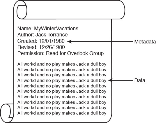
By definition, a file is a set of contiguous data that is persistently saved on a storage device. Besides enclosing proper user data, files also contain metadata, which is simply data describing user data. Common examples of file metadata include the filename, author name, access permissions, time and date of creation, and date of last revision. Figure 9-1 portrays a simple file structure for a file named MyWinterVacations. It contains data consisting of the repetition of a phrase that Jack Nicholson fans may find downright eerie. The file metadata defines the author name (Jack Torrance), date of creation (12/01/1980), last revision (12/26/1980), and permission (users from the Overlook Group can read the file).
You also learned in Chapter 8 that storage technologies are ultimately stacked in multiple abstraction layers. And as files’ data and metadata are stored on raw volumes (such as an HDD or SCSI LUNs on a disk array), storage devices require an additional layer of software to fully define where a file begins and ends. Consequently, a raw volume must be formatted to stock multiple files, which will then be controlled by many users. A corresponding file management application on users’ computers leaves them completely unaware of all block-related operations in the volume. Most operating systems (such as Linux and Windows) have long been equipped with file management applications, which perhaps explains how files became the customary unit of storage.
File Locations
A user can access files located in different places, which are generically represented in Figure 9-2.

First and most frequently, a user accesses local files when these data constructs are maintained in a direct-attached storage (DAS) device. But rather curiously, when a server is using an external SCSI volume on a disk array, it is actually saving files locally. After all, from a file management perspective, the files are being processed in this server.
Already inadequate in data centers, the practice of storing files in local storage is becoming as unfashionable as shoulder pads. In any scenario, local files represent a single point of failure, requiring individual backup procedures and manual operations to avoid data loss in the case of hardware failure.
File sharing allows users to access files located in other computers, through the use of a network infrastructure and a file access protocol. Although ad hoc file sharing may be attractive for environments with a low number of computers, it may easily become a management nightmare for companies with thousands of systems. In these organizations, seasoned IT administrators commonly preferred to store user files centrally in specialized computers called file servers. But as these servers had their capacity and robustness challenged with user file proliferation, they were gradually replaced with network-attached storage (NAS) devices. In essence, a NAS device is a specialized storage device with a large capacity that can serve files to a heterogeneous group of servers and personal computers.
A NAS may contain hundreds of hard disk drives and deploy aggregation technologies such as RAID and dynamic disk pools to increase access performance, data capacity, and file availability. But whereas disk arrays are connected to a storage-area network (SAN), a NAS formats volumes to handle files and exclusively communicate with clients through IP-based file sharing protocols such as Network File System (NFS) and Server Message Block (SMB).
From an architectural perspective, a NAS works as single point of arbitration to remote client systems, providing locks (to prevent other users from tampering with the files) and permissions (to prevent unauthorized access to files). These devices are commercialized through various vendors, such as NetApp Inc. and EMC Corporation.
Optionally, all NAS-related tasks can be performed on highly specialized appliances called NAS heads or NAS gateways. Using such devices, storage administrations can build NAS devices leveraging standard disk arrays. Consequently, a NAS head must provide a front-end network connection to file clients as well as a back-end SAN connection to access volumes on a disk array.
Main Differences Between Block and File Technologies
Based on the concepts discussed thus far, Table 9-2 delineates the main distinctions between block- and file-based storage technologies.


Table 9-2 contrasts block and file technologies through some key characteristics. For example, a client can store data using a single file as a provisioned unit, which offers a finer level of granularity when compared to a raw volume. On the other hand, because files demand additional processing to manage both data and metadata, NAS systems generally deliver a lower performance when compared to disk arrays. Such a characteristic reinforces how block technologies are usually positioned for a broader spectrum of applications.
Great flexibility normally conveys complexity. Block technologies assume that an application will fully control blocks in a volume, assigning more responsibilities to software developers. Furthermore, a SAN requires the installation and maintenance of a separate network infrastructure (in the case of a Fibre Channel SAN) and dedicated adapters on servers (HBAs).
Adversely, a NAS device can be deployed to provide centralized access to files through existing IP network and server network adapters. For this reason, file-based storage devices are not exclusive to servers and are also available to personal computers and workstations.
From a storage device administration standpoint, although a disk array controller can spawn volumes, it cannot control any data block contained within these constructs. Alternatively, file servers and NAS can control data format, metadata, client access, and many other internal aspects of a formatted volume.
Lastly, file-based storage systems can scale massively when compared to block technologies, which usually follow the one-volume-per-server rule on SANs.
Note
Considered a specific type of file, a database is a collection of highly organized information (records) that allows the retrieval and saving of select portions of data. The best analogy for a database is probably the telephone book, whose records have at least three types of data: name, address, and telephone number.
Database management systems (DBMSs) are generally composed of one or more database servers controlling storage devices (where data is actually saved) and providing record access to other applications. The most popular DBMSs are Oracle Database and Microsoft SQL Server.
Building a File System
A file system is defined as the methodology used for file management. Most computer systems have at least one file system, and there are various cases where several of them can be deployed simultaneously on a single computer.
A file system offers a hierarchical structure designed to organize, name, store, retrieve, and update a set of files. The structure resembles an inverted tree composed of a root directory and subdirectories (branches) that can contain files and other directories. The uniqueness of a file is defined through its place in the directory structure, its name, and (optionally) a suffix defining which type of content the file encompasses.
A file system also characterizes file metadata such as length, time of creation, time of last change, name of user who created it, which group the user belongs to, device type, and many other details. Additionally, the design of a file system should answer questions such as
![]() Which block-based structures are needed to store files’ and directories’ data and metadata?
Which block-based structures are needed to store files’ and directories’ data and metadata?
![]() How can files be located in a block volume?
How can files be located in a block volume?
![]() How should storage usage be optimized when dealing with files?
How should storage usage be optimized when dealing with files?
Although a detailed discussion of every characteristic of file systems is beyond the scope of this book, the next three sections will focus on some aspects that will help you understand basic file concepts. In these explanations, I will use as examples two of the most popular operating systems in servers today: Linux and Microsoft Windows.
File Namespace
A namespace is a set of symbols and rules that is used to organize different objects into a structure that assigns a distinct name to each object. Linux and Microsoft Windows deploy distinct hierarchical file namespaces, but both of them are based on the recursive logic of directories containing subdirectories and files forming a tree structure.
Tip
In this discussion, it may be useful to think of a directory as a special file accommodating names and other information about its contained files.
Linux File Naming Rules
All Linux versions consider a pathname to be the concatenation of all the components (directory, subdirectories, and filename) that uniquely defines a file. However, depending on the version you choose, the limitation in the depth of the file tree may vary.
As an example, the Linux file root/private/curriculum.txt belongs to the directory private located in the root directory. Its name is defined as curriculum.txt, which signals to applications that it is a text file.
Linux files are named through a combination of up to 255 characters, excluding reserved characters such as the forward slash (/), dollar sign ($), percent sign (%), brackets ([ and ]), less-than sign (<), greater-than sign (>), vertical bar (|), and ampersand (&).
Tip
Filenames should also never begin with a hyphen (-). Linux allows the use of special characters such as period (.) for hidden files, underscore (_), and even blank spaces in filenames. Nonetheless, to use any forbidden characters and wildcards in a file name, you should escape the character by putting it in quote marks or use the backslash () symbol before it.
Example 9-1 introduces several Linux commands that reveal some concepts behind file and directory management.
Example 9-1 File and Directory Name Examples in Linux
! This command shows that the user is in the root of the file hierarchical tree
# pwd
/
! This command shows all the files and directories in the root directory
# ls
bin dev home lib lost+found mnt proc run srv tmp var
boot etc initrd.img lib64 media opt root sbin sys usr vmlinuz
! Let's create a directory
# mkdir private
! Going into the private directory
# cd private
# pwd
/private
! Creating a file with a single phrase inside of it
# cat > file1.txt
Here's Johnny!
^D
! Checking if the file was created
# ls
file1.txt
! Reading the file content
# more file1.txt
Here's Johnny!
! Going back to the root directory
# cd ..
# pwd
/
Although Unix-like operating systems such as Linux do not require the use of file extensions, they can be genuinely useful to identify the purpose of a file at first sight and facilitate the management of groups of files (texts, executables, figures, and so on).
As a last remark, you should be aware that Linux is case-sensitive, meaning that uppercase and lowercase characters are not ignored. Therefore, file.txt, File.txt, and FILE.txt are three different files for Linux.
Windows File Naming Rules
Because they have inherited several characteristics from MS-DOS, Microsoft Windows platforms do not use the same conventions as Linux to name files and directories. In fact, directories are formally referred to as folders in all versions of this highly popular operating system.
Filename size limitations can vary depending on the adopted file system formatting, which will be explained in much more detail in the next section. Roughly speaking, older versions of Windows (still based on MS-DOS standards) supported a maximum of eight characters for the base filename and three characters for the extension separated by a period, which is commonly known as an 8.3 filename. Newer Windows releases support up to 260 characters for the whole pathname.
Ultimately, the most noticeable differences between Windows and Linux concerning file naming rules are as follows:
![]() Windows platforms use a backslash () to separate the components (folder, subfolder, and file) of a pathname.
Windows platforms use a backslash () to separate the components (folder, subfolder, and file) of a pathname.
![]() Logical drive names, such as C:, are required in Windows for the characterization of local pathnames.
Logical drive names, such as C:, are required in Windows for the characterization of local pathnames.
![]() Windows is not case-sensitive. Therefore, commands using file.txt, File.txt, and FILE.TXT are referring to the same file.
Windows is not case-sensitive. Therefore, commands using file.txt, File.txt, and FILE.TXT are referring to the same file.
![]() The reserved characters in Windows are less than (<), greater than (>), colon (:), double quote (“), forward slash (/), backslash (), pipe (|), question mark (?), and asterisk (*).
The reserved characters in Windows are less than (<), greater than (>), colon (:), double quote (“), forward slash (/), backslash (), pipe (|), question mark (?), and asterisk (*).
![]() Windows does not permit the use of names that are reserved for computer interfaces (such as CON, AUX, and COM1, among others) or ending a file with a space or a period.
Windows does not permit the use of names that are reserved for computer interfaces (such as CON, AUX, and COM1, among others) or ending a file with a space or a period.
Volume Formatting
Consisting of a set of contiguous information, files must follow a predefined standard format to allow correct identification of their data and metadata. Hence, if a block-based device or raw volume will store computer files, it must be formatted accordingly.
Extended Filesystems
The second extended filesystem (ext2) was created in 1993 to serve as a replacement for ext, the first file system specifically designed for the Linux kernel. In summary, ext2 was especially useful because it overcame the lack of flexibility and fragmentation issues ext suffered from. Despite its age, ext2 remains popular, being the default file system for many Linux distributions. For this reason, it is also the recommended choice for removable media.
An ext2-formatted volume is subdivided into blocks, which are consecutively assembled into block groups. But contrary to what you may be tempted to think, these block groups are not directly mapped to the physical layout of a hard disk drive. In fact, ext2 block groups are purposely allocated to minimize seek times and maximize performance on an HDD as much as possible. Hence, ext2 always attempts to save correlated file data in the same block group to decrease the average data access delay.
Note
Although volumes can also be divided into subvolumes, which are usually called partitions, I will not use this concept in any future explanation for the sake of simplicity.
Like many other file systems, ext2 is fundamentally based on the concept of index nodes (or inodes). This construct essentially represents a file (or directory) and contains data about its size, access permissions, ownership, and location on the volume (block addresses).
An inode has direct references to data blocks from a file, as well as indirect references that point to blocks containing direct references to file blocks. Similar to a block, each inode has a fixed size and an assigned numerical address, called inode number. ext2 reserves inodes 1 to 10 for special system use. For example, inode 2 contains information about the root directory, which is an extremely important stepping-stone in the file localization process.
Figure 9-3 further details the internal structure of an ext2 formatted volume.

Besides the boot sector (which may exist to initialize the computer), the volume is composed of block groups containing redundant copies of fundamental pieces of information about the whole file system, such as
![]() Super block: Contains all the essential information that defines the configuration of the ext2-formatted volume, such as total number of inodes, total number of blocks, free inodes and blocks, number of inodes and blocks per block group, and operating system and file system versions.
Super block: Contains all the essential information that defines the configuration of the ext2-formatted volume, such as total number of inodes, total number of blocks, free inodes and blocks, number of inodes and blocks per block group, and operating system and file system versions.
![]() Block group descriptor table: Stores a description of each block group within the file system, including the location of the inode bitmaps, inode tables, and number (quantity) of free blocks, among other information.
Block group descriptor table: Stores a description of each block group within the file system, including the location of the inode bitmaps, inode tables, and number (quantity) of free blocks, among other information.
Moreover, each block group also encompasses information about itself, including
![]() Block bitmap: Group of bits representing the current state of each block within a block group, where 1 means “used” and 0 means “free.”
Block bitmap: Group of bits representing the current state of each block within a block group, where 1 means “used” and 0 means “free.”
![]() Inode bitmap: Offers a similar quick reference about the use of inodes stored in the inode table from this block group.
Inode bitmap: Offers a similar quick reference about the use of inodes stored in the inode table from this block group.
![]() Inode table: Keeps information about every directory and file stored in the block group, including their location, size, type, and access rights stored in inodes. One exception: a filename is not stored in its inode, being contained in directories only.
Inode table: Keeps information about every directory and file stored in the block group, including their location, size, type, and access rights stored in inodes. One exception: a filename is not stored in its inode, being contained in directories only.
![]() Data blocks: Actual data from files and directories. These blocks are kept as close as possible to the block group’s inode table to improve access time.
Data blocks: Actual data from files and directories. These blocks are kept as close as possible to the block group’s inode table to improve access time.
Through this apparently complex arrangement, a computer CPU can easily locate a file within an ext2-formatted volume. As an example, imagine that file1.txt is located at the root directory. Hence, if a user desires to read the content of this file, the following sequence of events unfolds:
Step 1. Using the data contained in the superblock, the processor identifies how many blocks and inodes each block group contains.
Step 2. Accessing inode 2, the CPU reads the data describing the contents and characteristics of the root directory. In this data it finds the inode number from file1.txt.
Step 3. Because the CPU knows how many inodes each block group contains (both of them have fixed sizes), it locates the block group the file inode belongs to through a simple division operation. Using the block group descriptor table, it is also aware of the exact volume location (block address) for every inode table.
Step 4. The CPU accesses the inode table from the block group that contains the file. As shown in Figure 9-3, the file inode points to direct blocks that contain data from the file and also to an indirect block that points to more file blocks.
Note
Although I have not depicted these situations in Figure 9-3, inodes can also point to double-indirect blocks (which point to indirect blocks) and even triple-indirect blocks (which point to double-indirect blocks). Also, if the file was contained in another directory rather than the root, the CPU would use the same process to recursively discover the contents of each directory, which contains the name of its files and internal directories as well as their inodes.
With users demanding bigger files and volumes, new generations of file systems succeeded ext2. Table 9-3 displays the main scalability characteristics from ext2, ext3 (third extended filesystem), and ext4 (fourth extended filesystem).

In substance, ext3 is very similar to ext2. Two exceptions are optional compression and the journaling feature, where ext3 records all metadata changes to a special file in the volume, ensuring consistency through rollback to previous versions.
Besides sheer scale, ext4 brought the following functionalities to its formatted volumes:
![]() Extents: Replacing ext2 and ext3 block formatting, this construct allows up to 128 MB of contiguous space with 4-KB blocks. This feature increases performance and reduces fragmentation.
Extents: Replacing ext2 and ext3 block formatting, this construct allows up to 128 MB of contiguous space with 4-KB blocks. This feature increases performance and reduces fragmentation.
![]() Persistent pre-allocation: The file system can allocate space for a file in advance, reducing access delay and fragmentation for files that may scale fast.
Persistent pre-allocation: The file system can allocate space for a file in advance, reducing access delay and fragmentation for files that may scale fast.
![]() Journal checksum: Increases journaling reliability through integrity checking.
Journal checksum: Increases journaling reliability through integrity checking.
![]() Multiblock allocation: ext4 allows many blocks to be allocated to a file in a single operation, reducing the amount of CPU work to search for free blocks.
Multiblock allocation: ext4 allows many blocks to be allocated to a file in a single operation, reducing the amount of CPU work to search for free blocks.
Leaving the theoretical discussions aside for a moment, Example 9-2 depicts the formatting of a volume in Linux.
Example 9-2 Creating an ext2 File System
! Checking the available disks
# fdisk -l | grep '^Disk'
Disk /dev/sdb is not a valid volume
Disk /dev/sda: 17.2 GB, 17179869184 bytes
Disk /dev/sdb: 17.2 GB, 17179869184 bytes
! Formatting the volume without any recognizable formatting
# mkfs.ext2 /dev/sdb
mke2fs 1.42.9 (4-Feb-2014)
! As a delightful exercise, try to recognize some of the terms in the output below
Filesystem label=
OS type: Linux
Block size=4096 (log=2)
Fragment size=4096 (log=2)
Stride=0 blocks, Stripe width=0 blocks
1048576 inodes, 4194304 blocks
209715 blocks (5.00%) reserved for the super user
First data block=0
Maximum filesystem blocks=4294967296
128 block groups
32768 blocks per group, 32768 fragments per group
8192 inodes per group
Superblock backups stored on blocks:
32768, 98304, 163840, 229376, 294912, 819200, 884736, 1605632, 2654208,
4096000
Allocating group tables: done
Writing inode tables: done
Writing superblocks and filesystem accounting information: done
! After volume is formatted, a directory is created
# mkdir disk2
! Mounting the formatted device to the created directory
# mount /dev/sdb /disk2
#
The mount command executed in Example 9-2 frames a very important concept that will be further explored in this chapter. In Unix-like systems (and consequently all Linux versions), such operation enables a resource (such as an HDD or a volume) to be attached to the file hierarchical tree as a standard directory, bringing great simplification for file-related procedures.
FAT and NTFS
The most common file system formats used in Windows platforms are FAT16, FAT32, and NTFS. Although Linux distributions can also support these formats, ext2, ext3, or ext4 are usually deployed by default on local Linux volumes.
File Allocation Table (FAT) was originally developed in 1977 to format floppy disks (a once popular type of removable media that is now obsolete). Developed by Microsoft and IBM (among other companies), FAT is a simple and robust formatting standard that is compatible with almost every operating system, and for that reason, it is still heavily used on flash drives and devices used to boot computers.
FAT deploys an index table containing one entry for each cluster, which is an addressable contiguous area in a raw volume on a block-based storage device. Depending on the version of FAT and the size of the volume, a cluster can have from 512 bytes to 64 KB.
Figure 9-4 explains how FAT formatting organizes a volume.

As depicted in Figure 9-4, each FAT volume has five main sections. The first one, called boot partition, contains information about how the volume should be accessed by the computer, including size of cluster, FAT version, and if the volume is used to initialize its operating system for the computer.
For redundancy reasons, the file allocation table is stored twice in the formatted volume (FAT1 and FAT2). In this replicated index table, each entry contains information about its corresponding cluster, including if it is not used, the next cluster address for a file, and if it is the last cluster in a file.
The root folder has a fixed size and a specified location in a FAT volume to facilitate file location. In summary, this special folder has information for each of its files or folders, including metadata such as
![]() Name
Name
![]() File size
File size
![]() Creation date
Creation date
![]() Last access date
Last access date
![]() Last modified time
Last modified time
![]() Last modified date
Last modified date
![]() Starting cluster address in the file allocation table
Starting cluster address in the file allocation table
All files and other folders are stored in the remaining part of the volume. When files are being written in a FAT volume, the first free cluster is always used to store the next corresponding chunk of data. For this reason, the more that a FAT volume is used, the greater the likelihood that files may suffer from fragmentation issues as they are distributed among clusters that are distant from each other. As a result of fragmented files, the overall file access delay tends to increase.
Through the starting cluster address contained in the root folder, a computer CPU has a starting point to locate cluster entries from subfolders in a recursive manner, until it reaches the file in the hierarchy tree. Afterward, it collects the file data simply by following the sequence of clusters defined in the file allocation table.
Figure 9-4 also depicts how a file named file2.txt located in the root folder is accessed inside of a FAT volume. In more detail:
Step 1. The CPU goes to the root folder and locates entry file2.txt and its starting cluster address (0x1111).
Step 2. After reading the cluster content, the CPU has the first data portion from the file.
Step 3. The CPU accesses the file allocation table entry for this cluster and discovers the address for the next cluster (0x2222). It then reads the cluster content to obtain the second part of the file.
Step 4. The CPU accesses the file allocation table again, which points to cluster 0x3333.
Step 5. After reading the cluster, the CPU recognizes the end of the file in the cluster file allocation table entry.
There are several variants of FAT, but the most popular ones are represented in Table 9-4.

To avoid the file size limits and fragmentation issues from FAT-based technologies, Microsoft developed New Technology File System (NTFS) as an enhanced file formatting system. Starting with Windows NT (New Technology) 3.1, NTFS brought the following enhancements over FAT16 and FAT32:
![]() Permissions: NTFS assigns access restrictions to files and folders stored in an NTFS volume.
Permissions: NTFS assigns access restrictions to files and folders stored in an NTFS volume.
![]() Scalability: NTFS can use 64-KB clusters, allowing volumes with up to 256 TB and files of (potentially) 16 EB.
Scalability: NTFS can use 64-KB clusters, allowing volumes with up to 256 TB and files of (potentially) 16 EB.
![]() Journaling: Similarly to ext3 and ext4, NTFS records metadata changes to the volume as a safeguard measure against hardware failure.
Journaling: Similarly to ext3 and ext4, NTFS records metadata changes to the volume as a safeguard measure against hardware failure.
![]() Hard links: NTFS allows different filenames to refer to the same data content.
Hard links: NTFS allows different filenames to refer to the same data content.
![]() Compression: NTFS uses the LZNT1 algorithm to achieve compression rates of up to 4:1, depending on file data content.
Compression: NTFS uses the LZNT1 algorithm to achieve compression rates of up to 4:1, depending on file data content.
![]() Volume Shadow Copy Service: This NTFS process keeps historical versions of files and directories on NTFS volumes. For maximum availability, it is recommended to use a different volume for this data.
Volume Shadow Copy Service: This NTFS process keeps historical versions of files and directories on NTFS volumes. For maximum availability, it is recommended to use a different volume for this data.
![]() Encryption: NTFS provides encryption through Encrypting File System (EFS).
Encryption: NTFS provides encryption through Encrypting File System (EFS).
![]() Disk quotas: NTFS enables tracking and control of user disk space for NTFS-formatted volumes.
Disk quotas: NTFS enables tracking and control of user disk space for NTFS-formatted volumes.
In a Windows platform, a new storage device (or raw volume) can be formatted through administrative tools such as Computer Management from Windows Server 2008. Figure 9-5 depicts some formatting parameters when this operation is executed over a new volume from a disk array connected through a Fibre Channel SAN.

After a volume is formatted, Windows recognizes it as a logical drive represented as a capital letter and a colon (e.g., F:). And as previously explained in the section “Windows File Naming Rules,” a drive letter is always part of a local file pathname.
Note
You’ve been introduced to several different formats (FAT12, FAT16, FAT32, NTFS, ext2, ext3, and ext4), but this is not an exhaustive list of file systems. There are many other methods that can be used to organize files and directories in a storage device, some sharing characteristics with the presented standards and others with strikingly different approaches.
Permissions
One of the most important items in file and directory metadata is the permission, which essentially defines access restrictions according to users, computers, and user groups. In this section, you will learn some of the most interesting aspects about permissions on Linux and Windows operating systems.
Linux Permissions
Linux inherits the permissions defined for Unix systems, which are based on POSIX (Portable Operating System Interface) standards. In these operating systems, each file and directory has access restrictions for three classes of users:
![]() owner: Defines permissions that apply only to the owner of the file (or directory) and do not impact the actions of other users
owner: Defines permissions that apply only to the owner of the file (or directory) and do not impact the actions of other users
![]() group: Defines permissions that are only related to users that belong to the user primary (default) group, without any effect on the actions from other users.
group: Defines permissions that are only related to users that belong to the user primary (default) group, without any effect on the actions from other users.
![]() others: Defines permissions that apply to all other users not addressed in the owner and group classes
others: Defines permissions that apply to all other users not addressed in the owner and group classes
Using the Linux command-line interface, you can view the permissions through the ls -l command, as Example 9-3 illustrates.
Example 9-3 Verifying Files and Directories Permissions
! This command reveals more information about the files and directories
# ls –l
total 4
drwxr-xr-x 2 gsantana admgroup 80 2015-08-17 16:52 desktop
drwxr-xr-x 2 gsantana admgroup 40 2015-08-17 16:52 documents
-rwxrwxrwx 1 gsantana admgroup 131 2015-08-17 18:07 sample.txt
drwxr-xr-x 2 gsantana admgroup 40 2015-08-17 16:52 videos
In the example, you can check that each line refers to a directory or file that belongs to the root directory. The first letter of the permission strings signals if the described line is a file (-) or a directory (d).
In the subsequent characters of the permission strings, the first three letters refer to the user permissions (gsantana), the next three to group permissions (admgroup), and the last three to others permissions. For example, the sample.txt file has permissions rwx for all three classes.
These letters identify what each class can do with the file or directory, meaning
![]() read(r): Class can read the contents of the file or directory
read(r): Class can read the contents of the file or directory
![]() write(w): Class can write or modify a file or directory
write(w): Class can write or modify a file or directory
![]() execute(x): Class can execute a file or view the contents of a directory
execute(x): Class can execute a file or view the contents of a directory
The Linux chmod command is commonly used to change these permissions. Besides using the previously described permission code, the command may also use the following codes to represent the requested change:
![]() read: 4
read: 4
![]() write: 2
write: 2
![]() execute: 1
execute: 1
Example 9-4 clarifies how chmod can change permissions in a file.
Example 9-4 Changing Permissions on a Linux File
! Restricting access to a file
# chmod u=rwx,g=rx,o=r sample.txt
! Checking the file permissions
# ls -l sample.txt
-rwxrw-r-- 1 gsantana admgroup 131 2015-08-17 18:07 sample.txt
! Granting full access to the file
# chmod 777 sample.txt
# ls –l sample.txt
-rwxrwxrwx 1 gsantana admgroup 131 2015-08-17 18:07 sample.txt
! Restricting again
# chmod 755 sample.txt
# ls –l sample.txt
-rwxr-xr-x 1 gsantana admgroup 131 2015-08-17 18:07 sample.txt
With the last change in Example 9-4, the sample.txt file can be fully controlled by the gsantana user, while admgroup and all other users can only read and execute the file.
NTFS Permissions
As previously discussed in the section “FAT and NTFS,” NTFS introduced file (and folder) permissions to Windows operating systems. When compared to Linux permissions, NTFS permissions are a bit more sophisticated. Table 9-5 reinforces this statement through a brief description of the NTFS basic permissions.
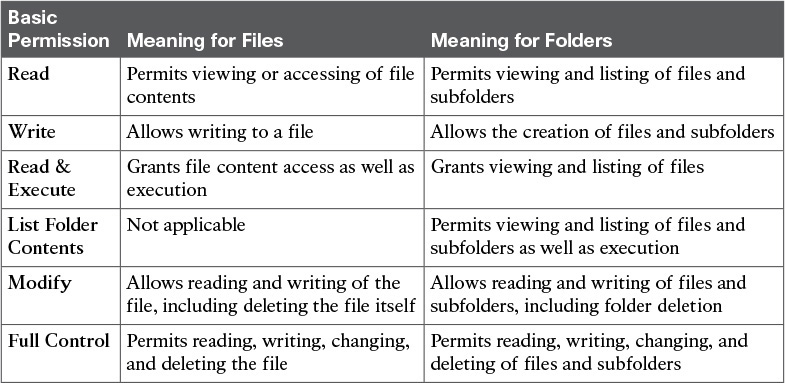
Table 9-5 does not contain all file and folder permissions that are possible in NTFS. In fact, these basic permissions are actually formed through the combination of more granular advanced permissions, such as
![]() Traverse Folder/Execute File: Allows a user to move through this folder to reach files and folders that are located inside of it. It also permits a user to run executable files.
Traverse Folder/Execute File: Allows a user to move through this folder to reach files and folders that are located inside of it. It also permits a user to run executable files.
![]() List Folder/Read Data: Allows a user to view files and subfolders within a folder. It also allows read access to the file contents.
List Folder/Read Data: Allows a user to view files and subfolders within a folder. It also allows read access to the file contents.
![]() Read Attributes: Allows a user to view the standard metadata of a file or folder.
Read Attributes: Allows a user to view the standard metadata of a file or folder.
![]() Read Extended Attributes: Allows a user to view customized extended attributes created by programs.
Read Extended Attributes: Allows a user to view customized extended attributes created by programs.
![]() Create Files/Write Data: Allows a user to create files within a folder. It also allows the user to make changes to the content of a file.
Create Files/Write Data: Allows a user to create files within a folder. It also allows the user to make changes to the content of a file.
![]() Create Folders/Append Data: Allows a user to create subfolders within a folder. It also allows the user to insert additional data at the end of the file.
Create Folders/Append Data: Allows a user to create subfolders within a folder. It also allows the user to insert additional data at the end of the file.
![]() Write Attributes: Allows a user to change the standard metadata of a file or folder.
Write Attributes: Allows a user to change the standard metadata of a file or folder.
![]() Write Extended Attributes: Allows a user to change customized extended attributes created by programs.
Write Extended Attributes: Allows a user to change customized extended attributes created by programs.
![]() Delete Subfolders and Files: Allows a user to erase subfolders and files of a defined folder. It supersedes the permission assigned to the subfolder or file.
Delete Subfolders and Files: Allows a user to erase subfolders and files of a defined folder. It supersedes the permission assigned to the subfolder or file.
![]() Delete: Allows a user to delete a file or folder.
Delete: Allows a user to delete a file or folder.
![]() Read Permissions: Allows a user to view the permissions assigned to a file or folder.
Read Permissions: Allows a user to view the permissions assigned to a file or folder.
![]() Change Permissions: Allows a user to change the permissions assigned to a file or folder.
Change Permissions: Allows a user to change the permissions assigned to a file or folder.
![]() Take Ownership: Allows a user to take ownership of a file or folder. By definition, the owner of a file or folder can always change permissions of a file or folder.
Take Ownership: Allows a user to take ownership of a file or folder. By definition, the owner of a file or folder can always change permissions of a file or folder.
As an example, the basic Read permission is formed through the union of Traverse Folder/Execute File, List Folder/Read Data, Read Attributes, and Read Extended Attributes. On the other hand, Full Control contains all advanced permissions. Although the complete description of all compositions of basic permissions is beyond the scope of this book, you can certainly appreciate the potential of advanced permissions for Windows administrators, who can use them to create customized permissions.
NTFS permissions were initially implemented in ad hoc Windows workgroups, where no computer has control over another computer. Modern Windows implementations use an authentication service called Active Directory to centrally control security and permissions for all Windows computers, files, and folders in an organization. Through this special-purpose user account database, Windows administrators can make changes that are automatically extended to a domain of potentially thousands of computers. Within an Active Directory domain, for example, a user can log on to any computer without the need for a local account.
To simplify the file and folder security in Active Directory domains, it is a best practice for Windows administrators to assign permissions for groups rather than for individual users. Because a group is a collection of user and computer accounts, it can be used to proactively assign permissions to files and folders before any account is provisioned.
In an NTFS volume, a file (or folder) can have its permissions related to individual Windows users, a group, or multiple groups. In a nutshell, a user can perform actions based on the sum of all the permissions assigned to the user and all the permissions assigned to all the groups the user is a member of (including the group that contains all users and groups, which is called Everyone).
The following are some additional rules that will help you further understand NTFS permissions on Windows-based systems:
![]() Basic Read permission is required to access a program shortcut as well as its target.
Basic Read permission is required to access a program shortcut as well as its target.
![]() If a user receives the permission to write to a file but not the permission to delete, she can still delete the file contents.
If a user receives the permission to write to a file but not the permission to delete, she can still delete the file contents.
![]() If a user has full control over a folder, he can delete files in the folder regardless of his permission over the files.
If a user has full control over a folder, he can delete files in the folder regardless of his permission over the files.
![]() If a user does not have any defined permission to a file, the user is denied access.
If a user does not have any defined permission to a file, the user is denied access.
As with many other features in Windows operating systems, the easiest way for an authorized administrator to access permissions is to right-click a file or a folder and choose Properties from the context menu. The Security tab is the typical location for setting permissions. For example, Figure 9-6 shows a file permission being accessed through Windows Explorer.

As you can see in Figure 9-6, all basic permissions can be assigned to a multitude of Windows users and groups.
Accessing Remote Files
As explained in the earlier section “File Locations,” computers can access files located in other systems. Consequently, many storage administrators have leveraged the benefits of file technologies to store user-accessible data in massively scalable network-attached storage systems.
When deploying multiple NAS within a data center, these administrators must design standards to facilitate coordinated file access to thousands of potential users and client computers. As a result, they end up deploying distributed file systems to simplify this endeavor.
In a nutshell, a distributed file system is a set of connected storage devices and clients that share files and directories using the same hierarchical directory structure. The available distributed file system solutions essentially differ from each other in achieved performance, handling of concurrent changes to a single file or folder, robustness against failures, and other aspects. Some of the most popular examples of distributed file systems are Sun Network File System, Microsoft Distributed File System (DFS), Ceph, GlusterFS, and Lustre.
Although these distributed file systems may use a variety of file access protocols, Network File System (NFS) and Server Message Block (SMB) are firmly established in the most popular operating systems.
In the next two sections, you will learn the main aspects of these file access protocols.
Network File System
Although its acronym is perhaps more commonly associated with the “Need for Speed” video game franchise, Network File System (NFS) is probably more entitled to it because of its age. Created by Sun Microsystems in 1984 for its Solaris operating system, NFS is still used by many other Unix-based operating systems, such as Linux and FreeBSD, as their native file access method.
Although its ease of use masks such complexity, NFS is characterized by a stack of protocols, as illustrated in Figure 9-7.

Unlike SANs, file access protocols always use IP networks to establish a session between client and server. Hence, the Internet Protocol enables NFS to run over any type of media (Layer 1) or networking technology (Layer 2). Furthermore, depending on which NFS version you may be using, the transport of data between file client and server may use TCP or UDP. However, all the versions share the same Layer 5 and 6 protocols, which are
![]() Open Network Computing Remote Procedure Call (ONC RPC): Also known as Sun RPC, this Layer 5 protocol enables communication between different remote file access processes for NFS.
Open Network Computing Remote Procedure Call (ONC RPC): Also known as Sun RPC, this Layer 5 protocol enables communication between different remote file access processes for NFS.
![]() External Data Representation (XDR): Also developed by Sun, XDR is a standardized data coding format that permits different computer systems to share data transmitted through NFS.
External Data Representation (XDR): Also developed by Sun, XDR is a standardized data coding format that permits different computer systems to share data transmitted through NFS.
NFS, XDR, and ONC RPC are standardized by the Internet Engineering Task Force (IETF). Both XDR and ONC RPC have multiple releases that support all three NFS versions, as shown in Table 9-6.

Both NFS versions 2 and 3 were created to be as stateless as possible, meaning that an NFS server does not need to maintain any client information (state) to provide access to files. On the contrary, NFS version 4 keeps states from clients to seamlessly re-create their sessions in the case of a server failure.
In the context of Table 9-6, synchronicity means that an NFS server can only send a positive response to the client after it has fully completed the client request, and any data associated with a write operation is safely saved on stable storage. In the case of NFSv3 and NFSv4, asynchronous writes may allow better performance, especially when there is a considerable latency separating client and server.
Although some implementations of NFS offer version interoperability, file-based storage administrators should always try to reduce the number of deployed versions in their environment to avoid compatibility problems between client and servers.
Common NFS Client Operations
Before any remote file or directory request, NFS clients must fulfill a mount operation to access a server remote file structure. In essence, mounting allows an NFS server to hand out remote access privileges to a restricted set of clients. And among these concessions, a client can attach a remote directory tree (server) to a local file system.
Figure 9-8 illustrates a mount operation initiated from an NFS client toward a NAS.

In Figure 9-8, the NAS has a defined NFS file tree rooted in the nfs_tree directory. Thus, the client mounts a local directory (/mnt/NFS/NFSvol/nfs_tree) to the remote server root directory, consequently joining the NAS tree to its own. Through this ingeniously simple procedure, a client can manage the NAS file tree as if it were a local directory.
Note
The mount operation is supported by the MOUNT protocol, which is intrinsically linked with the NFS stack. This protocol provides specific services that activate NFS, such as path lookup, user authentication, and authorization. And regardless of the chosen NFS version, the MOUNT protocol is stateful, mainly because the server must keep a list of client mount requests to avoid connection errors.
After a client successfully carries out a mount operation, an NFS server accepts its requests, which can be
![]() GETATTR: Returns the attributes of a file, including type of file, permissions, size of file, owner of file, and last access time.
GETATTR: Returns the attributes of a file, including type of file, permissions, size of file, owner of file, and last access time.
![]() SETATTR: Sets the attributes of a file such as permissions, owner, group owner, size, last access time, and last modification time.
SETATTR: Sets the attributes of a file such as permissions, owner, group owner, size, last access time, and last modification time.
![]() STATFS: Returns the status of the whole remote file system, including amount of available space, and optimal size for transfer.
STATFS: Returns the status of the whole remote file system, including amount of available space, and optimal size for transfer.
![]() LOOKUP: Required procedure that returns a file handle to the client, along with the attributes of the file. In a nutshell, a file handle is a server-generated number that uniquely identifies a shared file.
LOOKUP: Required procedure that returns a file handle to the client, along with the attributes of the file. In a nutshell, a file handle is a server-generated number that uniquely identifies a shared file.
![]() READ: Reads from a file using parameters such as a file handle, starting byte offset, and maximum number of bytes to read.
READ: Reads from a file using parameters such as a file handle, starting byte offset, and maximum number of bytes to read.
![]() WRITE: Writes to a file through parameters such as file handle, starting byte offset, number of bytes to write, and the data to write.
WRITE: Writes to a file through parameters such as file handle, starting byte offset, number of bytes to write, and the data to write.
![]() CREATE: Creates a file.
CREATE: Creates a file.
![]() REMOVE: Deletes a file.
REMOVE: Deletes a file.
![]() RENAME: Renames a file.
RENAME: Renames a file.
![]() MKDIR: Creates a directory.
MKDIR: Creates a directory.
![]() RMDIR: Deletes a directory.
RMDIR: Deletes a directory.
![]() READDIR: Reads a directory. It is used by the famous ls command.
READDIR: Reads a directory. It is used by the famous ls command.
If two clients access the same file and both of them are writing data to it, versioning problems could easily happen. To avoid this situation, file locking guarantees that other clients cannot access a file after it has been accessed by a user. Because NFS versions 2 and 3 are stateless, they require an additional protocol called Network Lock Manager (NLM) to provide file locking on NFS sessions. Like the MOUNT protocol, NLM was integrated into NFS version 4.
Common NFS NAS Operations
To give you perspective of how an NFS-based environment is operated, allow me to describe a NAS provisioning process of an NFS shared tree. Roughly speaking, a NAS administrator follows these steps:
Step 1. Create a NAS Volume: Through a GUI, the NAS administrator checks if there is space available in the system hard disk drives. Then, the administrator can create an aggregate (RAID group or dynamic disk pool) and a raw volume in it. Until this point, the NAS was managed using the same procedures that are usually conducted in disk arrays.
Step 2. Format the volume: In this step, the provisioned volume is formatted to contain files according to the administrator-defined requirements. Optionally, a tree can be created to provide directories and files before any user accesses it.
Step 3. Export: When an NFS server wants to share files, it exports a directory tree. In the scenario described in Figure 9-8, the NAS administrator exports the nfs_tree directory to be accessed by the clients. Among the parameters required for the operation, an export list can be created to define which clients may access the exported tree. At this point, clients can already mount to the exported tree and use it as a local directory.
Exports may also specify how a remote user may access a directory shared in a NAS using options, such as
![]() ro: The directory is shared read only, and the client cannot write to it.
ro: The directory is shared read only, and the client cannot write to it.
![]() rw: The client machine has read and write access to the directory.
rw: The client machine has read and write access to the directory.
![]() no_root_squash: If selected, then the root user on the client machine has the same level of access to the files on the system as the root user on the server.
no_root_squash: If selected, then the root user on the client machine has the same level of access to the files on the system as the root user on the server.
![]() no_subtree_check: If only part of the volume is exported, a process called subtree checking verifies if a file is in the appropriate part of the volume. If the entire volume is exported, disabling this option will accelerate file transfers.
no_subtree_check: If only part of the volume is exported, a process called subtree checking verifies if a file is in the appropriate part of the volume. If the entire volume is exported, disabling this option will accelerate file transfers.
![]() sync: Only enables synchronous writes.
sync: Only enables synchronous writes.
Server Message Block
Also known as SMB, Server Message Block is a client/server protocol used to request file services from server systems over a common network. Originally developed at IBM in the mid-1980s, SMB became the standard file access protocol in Microsoft operating systems (where it is known as Microsoft SMB Protocol).
Throughout Microsoft’s many Windows releases, multiple versions of SMB were deployed and officially defined as SMB dialects. One of the most famous dialects is called Common Internet File System (CIFS), which was proposed as an attempt to create an Internet standard for SMB in 1996. During that period, CIFS was being incorporated into Windows NT 3.51, and afterward it continued to be supported on Windows NT 4.0, Windows NT Workstation, Windows 98, and Windows 2000 platforms.
You will probably find many documents erroneously referring to CIFS and SMB as being synonymous. To avoid mistakes, just keep in mind the relationship between the protocols (CIFS is an SMB dialect) and disregard this incorrect oversimplification.
In summary, SMB demonstrates the following capabilities:
![]() File sharing
File sharing
![]() Dialect negotiation
Dialect negotiation
![]() Discovery of other SMB servers on the network (“network browsing”)
Discovery of other SMB servers on the network (“network browsing”)
![]() Printing
Printing
![]() File and record locking
File and record locking
![]() File and directory change notification
File and directory change notification
![]() File attribute handling
File attribute handling
SMB has evolved gradually over the past 30 years, but Figure 9-9 lists the main components of the modern SMB implementations.
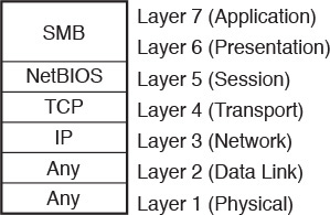
In Figure 9-9, you can observe that SMB is actually a protocol that consolidates functions from Layer 6 (presentation) and Layer 7 (application) from the OSI model. Therefore, SMB must transform direct requests from the user to operations that will be requested to the underlying protocols.
Network Basic Input/Output System (NetBIOS) works as a Layer 5 (session) protocol for SMB. Every NetBIOS-enabled computer has a 16-byte name and originally used broadcast messages to facilitate host discovery on local-area networks (default behavior before Windows 2000).
To overcome the challenges of this type of transmission, NetBIOS was ported to TCP connections (using port 445) and became known as NBT (NetBIOS over TCP/IP). With these enhancements, SMB also extended Windows networking to wide-area networks (WANs).
With the objective of tracing the evolution of SMB over the years, Table 9-7 describes the main characteristics of four of its versions.

Observe in Table 9-7 that SMB 1.0 was created to replace CIFS. Nevertheless, SMB 1.0 was severely criticized in many IT circles because it still exchanged an excessive number of messages between client and servers (chattiness). And as mentioned in Chapter 7, “Virtual Networking Services and Application Containers,” chattiness greatly contributes to application slowness in high-latency networks.
As a result, SMB 2.0 was introduced to overcome such challenges, with mechanisms such as
![]() Reduced command set: Decreased from over 100 commands to just 19 commands
Reduced command set: Decreased from over 100 commands to just 19 commands
![]() Pipelining and asynchronous operations: Permits additional requests to be issued before the response to a previous request arrives
Pipelining and asynchronous operations: Permits additional requests to be issued before the response to a previous request arrives
![]() Durable file handles: Allow an SMB session to survive brief network outages
Durable file handles: Allow an SMB session to survive brief network outages
![]() Larger I/O operations: Enable better traffic exchange between client and servers in high-latency networks
Larger I/O operations: Enable better traffic exchange between client and servers in high-latency networks
Recently, SMB 3.0 has brought benefits directly related to data center environments, such as SMB Direct Protocol, which enables SMB over Remote Direct Memory Access (RDMA). In this case, performance can be greatly increased when hosts can directly access the memory from other nodes of a high-performance computer (HPC) cluster without spending time and processing with the network stack. Additionally, SMB multichannel allows multiple physical connections to support a single SMB session, increasing performance and availability.
Note
Unix-like systems can also access SMB resources through the use of SAMBA, which constitutes an open source development effort to deploy Microsoft SMB Protocol in these systems. SAMBA continues to evolve with the progression of SMB.
Common SMB Client Operations
An SMB client accesses remote files using the concept of shares, which are formally defined as files, folders, or even a whole logical drive that can be shared through SMB sessions. From a client perspective, there are multiple ways to access shared files and folders. Figure 9-10 exposes one of them.

In this scenario, a shared folder (ingeniously called Share) in the host 10.97.39.200 is mapped to the local drive Z: in my Windows workstation. The following steps illustrate what happens within this successful mapping:
Step 1. Client and server establish a NetBIOS session.
Step 2. Client and server negotiate Microsoft SMB protocol version and dialect.
Step 3. Client logs on to the server.
Step 4. Client connects to a share on the server.
Step 5. Client accesses the folder.
From this moment, whatever operations are performed on this drive will be reflected in the SMB, including opening a file, writing in a file, listing the content of a folder, and so on.
Common SMB NAS Operations
Generally speaking, any Windows-based computer can share files. However, as previously discussed in the section “File Locations,” a NAS can offer scalability, availability, and flexibility that may not be found even in specialized computers serving as file servers.
The following are some of the high-level procedures that must be carried out to offer file-based storage in a NAS through SMB:
Step 1. Register the NAS to Active Directory: With this operation, the NAS administrator inserts the system into an Active Directory domain, leveraging all users and groups that are already created in it. Furthermore, the NAS is added as a resource that can be discovered and mapped as a logical drive by Windows servers and desktops.
Step 2. Create the NAS volume: Through a GUI, the NAS administrator checks if there is available space in the system HDDs. Then, the administrator can create an aggregate (RAID group or dynamic disk pool) and a raw volume over it.
Step 3. Format the volume: In this case, the volume is formatted with NTFS to reflect the file security that is already implemented on Active Directory domains. Optionally, a folder tree can be created to provide files and folders to be accessed by users.
Step 4. Sharing: Finally, the tree is shared so that it can be accessed by the clients.
By definition, the security model of Microsoft SMB Protocol has two levels of security: user and share. While user-level authentication indicates which users and groups can access a share, as described in the section “NTFS Permissions,” share-level authentication indicates that access to a share must be controlled by a password that is exclusively assigned to it.
Most NAS systems can perform both types of authentication, leveraging their relationship with Active Directory.
Other File Access Protocols
Although both NFS and SMB have software clients integrated into most operating systems, they are not the only available protocols to access and exchange files across a network. As an illustration, here is a list of open protocols that can also perform this task for users and applications:
![]() File Transfer Protocol (FTP): Created at the dawn of the Internet (1971), FTP is an IETF-standardized file transfer protocol that runs over TCP using two different connections for control and data exchange between client and server. Secure File Transfer Protocol (SFTP) is a more robust version of the protocol that was launched in 2001 to improve security.
File Transfer Protocol (FTP): Created at the dawn of the Internet (1971), FTP is an IETF-standardized file transfer protocol that runs over TCP using two different connections for control and data exchange between client and server. Secure File Transfer Protocol (SFTP) is a more robust version of the protocol that was launched in 2001 to improve security.
![]() Trivial File Transfer Protocol (TFTP): Protocol that requires a very simple client and is designed for boot and firmware loading during device initialization. Released in 1981, TFTP leverages UDP in the communication between client and server.
Trivial File Transfer Protocol (TFTP): Protocol that requires a very simple client and is designed for boot and firmware loading during device initialization. Released in 1981, TFTP leverages UDP in the communication between client and server.
![]() Secure Copy Protocol (SCP): Network protocol that supports file transfers through an SSH (Secure Shell) connection in TCP port 22. SCP is generally installed by default in most Linux distributions.
Secure Copy Protocol (SCP): Network protocol that supports file transfers through an SSH (Secure Shell) connection in TCP port 22. SCP is generally installed by default in most Linux distributions.
![]() Hypertext Transfer Protocol (HTTP): As one of the pillars of the World Wide Web, HTTP was originally designed to transfer objects between web servers and browsers. HTTP Secure (HTTPS) provides secure access to web pages, while Web Distributed Authoring and Versioning (WebDAV) allows users to create, read, update, and delete documents in a web server.
Hypertext Transfer Protocol (HTTP): As one of the pillars of the World Wide Web, HTTP was originally designed to transfer objects between web servers and browsers. HTTP Secure (HTTPS) provides secure access to web pages, while Web Distributed Authoring and Versioning (WebDAV) allows users to create, read, update, and delete documents in a web server.
![]() Apple Filing Protocol (AFP): Proprietary protocol that offers file services for Apple Mac operating systems. It was previously known as AppleTalk.
Apple Filing Protocol (AFP): Proprietary protocol that offers file services for Apple Mac operating systems. It was previously known as AppleTalk.
Cloud Computing and File Storage
With their basic concepts ingrained in the minds of every computer user, files and directories certainly play a significant role in cloud computing. And, as this section explores, the relationship between file systems and cloud environments can be placed in two contexts: file storage as a part of the cloud infrastructure or file storage as an offer to cloud users. The section also explores OpenStack’s file service, which is called Manila.
File Storage for Cloud Infrastructure
As you learned in the section “Main Differences Between Block and File Technologies,” file-based storage devices present advantages over block-based storage devices, including massive scalability and active control over stored data. For elastic multi-tenant environments, these characteristics are indeed a great fit.
One straightforward example is the use of NAS systems as shared storage for server virtualization clusters. In these scenarios, hypervisors can use a distributed file system to store virtual machine files.
Naturally, each hypervisor vendor tends to favor its own choice of distributed file system to store VM files, but most vendors are flexible about this choice. For example, although VMware offers its vSphere Virtual Machine File System (VMFS) as the default for VMware ESXi implementations to format block-based volumes, such implementations may instead leverage NFS servers to store VM files.
Consistent with their Linux origins, Kernel-based Virtual Machine (KVM) and Xen clusters traditionally mount their VM files on NFS-based NAS devices or file servers. And as you may expect, Microsoft Hyper-V leverages SMB to access VM files to implement storage features from the latest versions from this protocol.
Considering the flexibility required in cloud computing scenarios, many storage administrators opt to deploy systems that can allow access through a diverse range of methods, including both block and file protocols. With such a hybrid storage device, NFS, SMB, and iSCSI can easily run over the same IP network infrastructure, thereby simplifying the installation of new physical servers.
Furthermore, as you will learn in Chapter 10, “Network Architectures for the Data Center: Unified Fabric,” a unified fabric supporting Fibre Channel over Ethernet (FCoE) can avoid the requirement of a separate network infrastructure to provide the exact behavior expected from Fibre Channel SANs.
File Hosting
Providing external access to files is an extremely popular cloud service. In this case, files can be stored, read, updated, and deleted according to a predefined agreement. The service may involve charges related to storage usage or it may be free.
Your first encounter with the word “cloud” in the context of computing was likely associated with a popular file hosting service such as Google Drive, Box, Dropbox, and Apple iCloud, all of which provide capacity for users to store and read files. But beyond storing personal information, these providers also offer specialized file services such as the following:
![]() Backup: Provides automated copies for files stored in a personal computer as well as enterprise servers. Many cloud providers have developed enhancements that are usually offered as options, such as the type of backup (continuous, incremental), file synchronization, scheduling, and bandwidth control.
Backup: Provides automated copies for files stored in a personal computer as well as enterprise servers. Many cloud providers have developed enhancements that are usually offered as options, such as the type of backup (continuous, incremental), file synchronization, scheduling, and bandwidth control.
![]() Security: Offers secure storage through file encryption and typically includes options for users to use their own keys, replicate data in two different geographic regions, and manipulate myriad file and directory permissions.
Security: Offers secure storage through file encryption and typically includes options for users to use their own keys, replicate data in two different geographic regions, and manipulate myriad file and directory permissions.
![]() Content Delivery Network (CDN): Through this service, data centers may save bandwidth resources and leverage the pervasive Internet presence of CDN service providers to optimally distribute content stored in files.
Content Delivery Network (CDN): Through this service, data centers may save bandwidth resources and leverage the pervasive Internet presence of CDN service providers to optimally distribute content stored in files.
Regardless of the use case, most file services deployed on public clouds tend not to deploy NFS or SMB protocols, mainly because of the challenges they pose with the intrinsic latency of the Internet. HTTP has quickly assumed leadership as the main file transfer protocol for cloud file projects, for reasons such as these:
![]() HTTP does not suffer from the same chattiness issues as NFS and SMB.
HTTP does not suffer from the same chattiness issues as NFS and SMB.
![]() HTTP offers acceptable security through HTTPS.
HTTP offers acceptable security through HTTPS.
![]() The overwhelming majority of computers and smart devices are equipped with a web browser.
The overwhelming majority of computers and smart devices are equipped with a web browser.
![]() Firewall rules generally allow HTTP sessions for web surfing, simplifying access to file hosting service providers.
Firewall rules generally allow HTTP sessions for web surfing, simplifying access to file hosting service providers.
OpenStack Manila
Introduced in 2014, Manila is a project whose objective is to provide file-based storage for OpenStack clouds. Based on OpenStack Cinder (which was briefly discussed in Chapter 8), Manila primarily offers to Nova instances coordinated access to shared or distributed file systems.
The project is sponsored by NetApp, Mirantis, Red Hat, EMC, and IBM, and currently supports file sharing through NFS and SMB (although more protocols are expected to follow in future releases). The main concepts behind OpenStack Manila are
![]() Share: Instance of a shared file system with a defined access protocol, size, and an access list composed of share access rules.
Share: Instance of a shared file system with a defined access protocol, size, and an access list composed of share access rules.
![]() Share access rules: Access-list entries that determine which client IP addresses are authorized to access one share.
Share access rules: Access-list entries that determine which client IP addresses are authorized to access one share.
![]() Share network: Defines the network (Layer 2 domain) and subnet (Layer 3 addresses) through which the instances can access the share.
Share network: Defines the network (Layer 2 domain) and subnet (Layer 3 addresses) through which the instances can access the share.
Tip
Both subnet and network constructs belong to Neutron, an OpenStack project that will be further explained in Chapter 11, “Network Architectures for the Data Center: SDN and ACI.”
![]() Security service: More granular client access rules for client authentication and authorization, which includes integration with Lightweight Directory Access Protocol (LDAP) servers, Active Directory, and Kerberos servers.
Security service: More granular client access rules for client authentication and authorization, which includes integration with Lightweight Directory Access Protocol (LDAP) servers, Active Directory, and Kerberos servers.
![]() Snapshot: Point-in-time copy of a share that can be used to create a new share.
Snapshot: Point-in-time copy of a share that can be used to create a new share.
![]() Backend: Storage device, such as a NAS, that actually provides the shares. It is very important that you understand that Manila is never on the data path between the file client (instance) and server (backend).
Backend: Storage device, such as a NAS, that actually provides the shares. It is very important that you understand that Manila is never on the data path between the file client (instance) and server (backend).
![]() Driver: Piece of software that maps standard Manila operations to vendor-specific commands.
Driver: Piece of software that maps standard Manila operations to vendor-specific commands.
Through a REST API, a process called manila-api receives requests from OpenStack Horizon (or any other software) to create, delete, list, and rename shares. Meanwhile, the manila-scheduler process queues share requests, while multiple manila-share processes (one for each backend) take care of the communication with storage systems.
Following a client/server provisioning model, all shares are mounted from the instances. At the time of this writing, there are multiple ways Manila can offer shares, depending on the type of backend the cloud provider wants to use.
Figure 9-11 depicts the “generic” share provisioning method.

As Figure 9-11 illustrates, this method relies on the creation of Cinder block volumes that are controlled by a Nova instance that solely exists to provide file shares to other tenant instances. Whereas the share instance can provide remote file access through NFS or SMB, it can access the volume through a block access protocol such as iSCSI.
On the other hand, Manila can also use third-party vendor drivers to allow the creation of shares on backend storage devices to provide file access to tenant instances. Figure 9-12 clarifies this method.

As shown in Figure 9-12, after Manila receives a request for another share, it instructs an integrated backend device (NAS) to create a new file system through a supported plug-in. Manila also requires the creation of a Neutron network that connects tenants to the newly created share in the NAS.
Around the Corner: Object Storage
Risking an oversimplification, I would say that the choice between block- and file-based storage is guided by two factors: performance and scale. Nonetheless, new applications’ requirements are pushing the edge of this spectrum beyond the scale achieved by file systems, and therefore, leaving further behind the strong consistency that block storage offers.
For this kind of application, a concept called object-based storage seems to be the strongest fit. In such context, an object is a construct that contains data, a globally unique identifier, and both a variable and a flexible amount of metadata. Unlike file systems, object storage does not possess a hierarchical structure of directories, because it employs only a flat namespace that contains all objects.
Object storage systems are intended to support massive amounts of unstructured data, and thus do not have to worry about abstractions such as aggregate groups and volumes. Generally, these systems are built over x86 servers (referred to as nodes) rather than specialized equipment such as disk arrays or NAS devices. Hence, the internal storage from these servers is used to store the objects, which are always replicated on other nodes to increase data availability. Moreover, scalability is achieved with the insertion of additional nodes.
Through the designed simplicity of object storage, these systems only provide an object after a request and only allow manipulation of the whole unit, never just a part of it. Only applications that are mostly read-oriented, with minimal writes or incremental updates, are usually recommended to use object-based storage. Some examples are social networking, data backup, archival imaging, and multimedia applications.
The flexible metadata of objects enables some capabilities that are extremely hard to replicate in file systems. For example, an object allows the creation of custom metadata such as genre, data center site, tenant, publisher, and other details that may be limited only by your imagination. Because this metadata can be used in the distribution of objects across the nodes, the location of a single object beneath petabytes of information is drastically simplified, even enabling the client to infer which nodes host the object.
Some of the prominent object storage solutions at the time of this writing are
![]() Ceph: Open source software designed to present block, file, and object storage through an algorithm called CRUSH (Controlled Replication Under Scalable Hashing), which ensures that data is evenly distributed across the cluster. This system has self-healing capabilities that eliminate the possibility of a single point of failure, even after a hardware malfunction.
Ceph: Open source software designed to present block, file, and object storage through an algorithm called CRUSH (Controlled Replication Under Scalable Hashing), which ensures that data is evenly distributed across the cluster. This system has self-healing capabilities that eliminate the possibility of a single point of failure, even after a hardware malfunction.
![]() Amazon Simple Storage Service (S3): Provides developers and IT teams with secure, durable, highly scalable object storage.
Amazon Simple Storage Service (S3): Provides developers and IT teams with secure, durable, highly scalable object storage.
![]() OpenStack Swift: Object store project that offers massive scale with a simple API. Some companies, such as SwiftStack, offer OpenStack Swift as an enterprise solution.
OpenStack Swift: Object store project that offers massive scale with a simple API. Some companies, such as SwiftStack, offer OpenStack Swift as an enterprise solution.
Due to their intensive use of APIs, these solutions generally employ HTTP as the object access protocol.
Further Reading
![]() Ceph: http://ceph.com/
Ceph: http://ceph.com/
![]() Amazon S3: http://aws.amazon.com/s3/
Amazon S3: http://aws.amazon.com/s3/
![]() OpenStack Swift: http://docs.openstack.org/developer/swift/
OpenStack Swift: http://docs.openstack.org/developer/swift/
Exam Preparation Tasks
Review All the Key Topics
Review the most important topics in this chapter, denoted with a Key Topic icon in the outer margin of the page. Table 9-8 lists a reference of these key topics and the page number on which each is found.

Complete the Tables and Lists from Memory
Print a copy of Appendix B, “Memory Tables” (found on the CD), or at least the section for this chapter, and complete the tables and lists from memory. Appendix C, “Answers to Memory Tables,” also on the CD, includes completed tables and lists so that you can check your work.
Define Key Terms
Define the following key terms from this chapter, and check your answers in the glossary:
network-attached storage (NAS)
New Technology File System (NTFS)
External Data Representation (XDR)
Common Internet File System (CIFS)
Network Basic Input/Output System (NetBIOS)
Trivial File Transfer Protocol (TFTP)
Hypertext Transfer Protocol (HTTP)
Hypertext Transfer Protocol over SSL (HTTPS)
Web Distributed Authoring and Versioning (WebDAV)
Virtual Machine File System (VMFS)